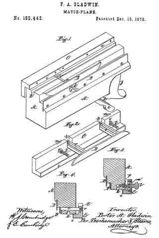
No. 306,763 – Plane (Stephen G. Laskey) (1884)

[paiddownloads id=”375″]306763


UNITED STATES PATENT OFFICE.

_________________

STEPHEN G. LASKEY, OF CHELSEA, MASSACHUSETTS.

PLANE.

_________________

SPECIFICATION forming part of Letters Patent No. 306,763, dated October 21, 1884.
Application filed February 7, 1884. (No model.)

_________________

To all whom it may concern:

Be it known that I, STEPHEN G. LASKEY, of Chelsea, in the county of Suffolk, State of Massachusetts, have invented a certain new and useful Improvement in Planes, of which the following is a description sufficiently full, clear, and exact to enable any person skilled in the art or science to which said invention appertains to make and use the same, reference being had to the accompanying drawings, forming a part of this specification, in which —

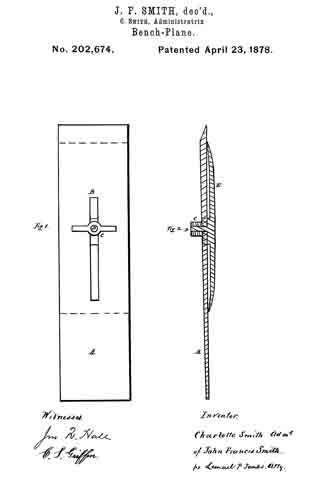
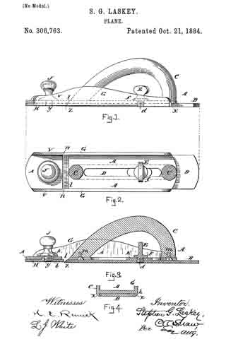
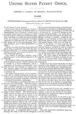
Figure 1 is a side elevation of my improved plane; Fig. 2, a top plan view with the handle removed; Fig. 3, a vertical longitudinal section, and Fig. 4: a vertical transverse section of the body and iron.

Like letters of reference indicate corresponding parts in the different figures of the drawings.

My invention relates more especially to the class of planes known as “block” planes; and it consists in a novel construction and arrangement of the parts, as hereinafter more fully set forth and claimed, by which a simpler, cheaper, lighter, and more effective device of this character is produced than is new in ordinary use.

The nature and operation of the improvement will be readily understood by all conversant with such matters from the following explanation, its extreme simplicity rendering an elaborate description unnecessary.

In the drawings, A represents the body, B the iron, and C the handle. The body is preferably composed of metal, and is provided with a dovetail channel, h, extending longitudinally along its under side to receive the iron, which is correspondingly beveled at the edges to fit the channel. The handle is preferably evolute in form, and is secured to the upper side of the body by the screws m, as shown in Fig. 3. The body is provided on either side with a vertical flange, G, and at its center with an elongated slot, D, extending lengthwise thereof between the ends of the handle, and fitted to work therein is a thumb-screw, E, having a wide annular flange, f, the screw entering a threaded hole, d, in a hub, K, on the iron, the hub projecting upwardly into the slot. A transverse slot, l, is cut through the body A. between the flanges G, the rear wall of this slot being inclined toward the handle C, the incline corresponding nearly with the incline of the cutting or beveled end z of the iron B. A shoe, H, having an upwardly-extending flange, v, on either side, is attached to the forward end of the plane, the flanges working in rabbets n, formed in the flanges G, and the face or lower side of the shoe being flush with the lower edges of the last-named flanges, which are cut away forward of the throat l to form ways for the shoe. A thumb-screw, J, provided with an annular flange, p, is fitted to work in a hole in the forward end of the body A, the screw entering a correspondingly-threaded hole, y, in a hub, b, on the shoe H, and the flange resting on the upper side of the body above the shoe. The lower edges of the flanges G are slightly rounded or beveled, as shown at x in Fig. 4, to prevent them from resting with their entire surface on the wood or article being planed.

In the use of my improvement the iron B is inserted in the channel h in the body A., with the bevel of its cutting end z uppermost, and, after being properly adjusted with respect to the throat l, is secured in position by turning in the screw E and bringing the flange f into forcible contact with the upper side of the body. The shoe H is then raised or lowered, as the case may be, by turning the screw J to the right or left until the lower side or face of the shoe is elevated above the lower side or face of the iron B a distance corresponding with the kerf or thickness of the shaving it is desired to cut, the plane being then ready for use.

I am aware that it is not new, broadly, to construct a plane in which the plane-iron constitutes a part of the bottom of the stock, said plane-iron being driven tightly into dove-tail grooves in said stock.

I am also aware that it is not new to construct a plane with a plane-iron arranged flat-wise in a recess in the under side of the stock extending backward a short distance from the throat, the rear end of said plane-iron being flush with the bearing-surface of the stock and the front end thereof adjustable vertically.

I am also aware that adjustable shoes are not new, broadly.

Having thus explained my invention, what I claim is —
1. The combination of a stock provided with a transverse throat, a dovetailed recess on its under side, and a longitudinal slot in rear of the throat, a plane-iron adapted to fit said recess, provided with a boss projecting into said slot, and having a threaded socket and a thumb-screw which enters said socket, and has a flange which projects over the side of the slot, substantially as described.

2. The combination of a stock provided with rabbets in its side checks and with at slot in its bottom in front of the throat, an adjustable shoe provided with upwardly-projecting flanges adapted to slide in said rabbets, and with a socket projecting upward into said slot, and a set-screw for adjusting said shoe, substantially as described.

STEPHEN G. LASKEY.

Witnesses:
C. A. SHAW,
L. J. WHITE.

No. 202,674 – Improvement In Bench-Planes (Charlotte Smith) (1878)

[paiddownloads id=”290″]202674


UNITED STATES PATENT OFFICE.

_________________

CHARLOTTE SMITH, OF CHELSEA, MASSACHUSETTS, ADMINISTRATRIX OF JOHN F. SMITH, DECEASED.

IMPROVEMENT IN BENCH-PLANES.

_________________

Specification forming part of Letters Patent No. 202,674, dated April 23, 1878; application filed March 26, 1878.

_________________

To all whom it may concern:

Be it known that I, CHARLOTTE SMITH, of Chelsea, Suffolk, State of Massachusetts, administratrix of the estate of my deceased husband, JOHN FRANCIS SMITH, of said city, county, and State, do declare that the said deceased, during his lifetime, did invent a new and useful Plane-Iron Cap, of which the following is a specification:

The nature of the invention is that of a plate of metal of peculiar form, detachable, but when in use fastened by a peculiar device to one side of a plane-iron, being an improvement on the well-known plane-iron top of a carpenter’s plane; and the object of the improvement is to effect the ready removal of the top when required, and also the firmer holding it in place when in use.

Figure 1 is a view of one side of the plane-iron, showing the nut used to fasten the top, and the necessary slot in the plane-iron, &c. Fig. 2 is a vertical cross-section, giving the relative positions of the plane-iron, the top with its screw, and the nut of the same.

In the drawings, A, Figs. 1 and 2, is the plane-iron or blade of a carpenter’s plane. B, Fig. 1, is a slot in the same, of any convenient length or width, running lengthwise of the plane-iron. C, Figs. 1 and 2, is a nut, with a projection each side of it, (seen in Fig. 1,) forming a thumb-screw, a, being worked by the thumb and finger, screwed onto the screw D, Figs. 1 and 2, which screw passes through the slot B, Fig. 1, as seen in Fig. 2, and at the right-hand side in Fig. 2 is attached to the plane-iron top E, Fig. 2. A shoulder (seen in both figures, in dashed lines in Fig. 2) is attached to the base of the screw D, and also to the top E, and is cut away (see Fig. 1) on each side of the screw D, so as to enter into the slot B.

The inner surface of the top E is seen in Fig. 2 not to lie flat on the plane-iron, but to rest on the same by its ends, which are both, in the same figure, seen to be curved. The thinness of the top E, with the two curves noted, makes of it a spring of greater or less strength, as the thickness of the top E may vary.

It is not proposed to confine ourselves to any particular thickness of the top, nor to any particular curve of the ends. A circular enlargement is sometimes made of the slot B near one or the other end; but this is not claimed here as original.

The length of the shoulder portion left on entering into the slot B may be varied. The whole device of the top and its attachment may be adapted to any plane-iron, the size of the thumb-screw being varied to suit the width of th slot which may be borne by the plane-iron.

Operation: The parts of the device being in place, as seen in the drawings, the nut C is turned by the thumb and finger, thus bending, more or less, the top E and pressing the curved ends more tightly on the plane-iron. When the top E is to be removed there is no loss of time in searching for a screw-driver; but the thumb-screw C is readily turned by the thumb and finger, as before, and the top E is at once loosened; and if the slot B is cut as drawn in Fig. 1, the thumb-screw C is removed, when the top E is readily removed to admit the sharpening of the cutting-edge of the plane-iron.

If the circular enlargement referred to as optionally provided is present, the nut need not be removed, the thumb-screw arms in that case passing through the slot B.

I do not claim the providing the top with a single curved end.

I claim for the inventor —

1. The double curved plane-iron top shown, in combination with the plane-iron, the shoulder, the screw D, and a nut, all when constructed and fitted for use, substantially as described and shown.

2. The combination of the thumb-screw with its arms, the screw D, the shoulder seen, a plane-iron, and a plane-iron top, all when constructed and arranged substantially as described and shown.

CHARLOTTE SMITH,
Admimistratrar of John Francis Smith.

Witnesses:
JOS. B. BELL,
LEMUEL P. JENKS.

No. 191,393 – Improvement In Bench-Planes (Watson Wood) (1877)

[paiddownloads id=”278″]191393


UNITED STATES PATENT OFFICE.

_________________

WATSON WOOD, OF CHELSEA, MASSACHUSETTS.

IMPROVEMENT IN BENCH-PLANES.

_________________

Specification forming part of Letters Patent No. 191,393, dated May 29, 1877; application filed February 26, 1877.

_________________

To all whom it may concern:

Be it known that 1, WATSON WOOD, of Chelsea, in the county of Suffolk and State of Massachusetts, have invented an Improvement in Bench-Planes, of which the following is a specification:

In the accompanying drawing, Figure 1 represents a side view of a plane, partly in section, to show my improved oiling attachment; and Fig. 2 is a top view of the same.

Similar letters of reference indicate corresponding parts.

The invention has reference to an oiling attachment to iron or iron-faced planes, by which the objectionable sticking or friction of the same on wood is obviated; and the invention consists of an iron or iron-faced plane, having an oil-receptacle and feed device in front of the cutting-iron.

In the drawing, A represents a plane of any approved construction, being either entirely of iron or of wood with an iron face. A small hole, a, is drilled through the face of the plane in front of the cutting-iron and in the center of the face. This hole is connected, either by a small tube or directly, with an oil-receptacle, B, that may be either cast on the plane inside of the knob which is generally used as a handle, or otherwise attached to the same. The oil-receptacle B is closed by a knob, G, that is secured or otherwise applied in air-tight manner thereto. A wick or piece of soft leather is arranged at the inside of the receptacle and in the feed-hole et, so as to prevent the oil from being fed too fast on the face of the plane. The wick or other device admits only the escape of a quantity of oil sufficient to allow the iron-faced plane to run smoothly and easily over the wood, giving the iron face sufficient lubrication to destroy the friction or sticking of the same on the wood without greasing the work or the hands of the person using the plane.

When the plane is not in use no oil will escape, and, as no air can get in, it will last for a long time, and not gum at all. The face of the plane, being always oily, will not rust, nor will the iron rust, as the shavings that are cut by it supply a small quantity of grease to it, which leaves the iron in a good condition for any length of time, the oil-trap forming thus a useful attachment to the plane that facilitates the working with iron-faced planes.

I am aware that it is not new to set a soap-stone in front of a plane-iron; but

What I claim is —

The combination of plane A, having hole a, and the oil-reservoir B, the two connected directly or by tube with each other, substantially as and for the purpose specified.

WATSON WOOD.

Witnesses:
FRANK T. WARE,
EBEN HUTCHINSON.

No. 185,442 – Improvement In Match-Planes (Porter A. Gladwin) (1876)

[paiddownloads id=”273″]185442


UNITED STATES PATENT OFFICE.

_________________

PORTER A. GLADWIN, OF CHELSEA, MASSACHUSETTS.

IMPROVEMENT IN MATCH-PLANES.
_________________

Specification forming part of Letters Patent No. 185,442, dated December 19, 1876; application filed November 6, 1876.

_________________

To all whom it may concern:

Be it known that I, PORTER A. GLADWIN, of Chelsea, in the county of Suffolk and State of Massachusetts, have invented certain Improvements in Match-Planes, of which the following is a full, clear, and exact description, reference being had to the accompanying drawings, making part of this specification, in which —

Figure 1 is a perspective view of my match-plane inverted. Fig. 2 is a perspective view of the two movable gages connected together and detached from the plane. Figs. 3 and 4 are transverse vertical sections.

My present invention relates to certain improvements in match-planes for which Letters Patent of the United States No. 17,541 were granted to me June 9, 1857.

The stock of the plane referred to was constructed so as to receive and hold a double iron-one portion for tonguing and the other for grooving–two stationary gages being employed in connection with this double iron; but on account of these gages being stationary only one thickness of material could be matched with a single plane, and consequently a number of these tools were required to match boards of different thicknesses.

My invention has for its object to provide a single match-plane, which can be so adjusted as to adapt it for boards of various thicknesses; and consists in a pair of movable gages, in combination with a stock provided with both a tonguing and a grooving iron.

My invention also consists in so connecting or coupling these gages that they may be moved simultaneously in the same direction, in order thereby to insure the perfect matching of two boards of the same thickness.

My invention furthermore consists. in making one of the gages adjustable independently of the other, in order that the relative position of one gage may be slightly changed with respect to that of the other, whereby the tongue and groove may be so located that the surfaces of the two boards to be matched will lie flush with each other.

To enable others skilled in the art to understand and use my invention, I will proceed to l describe the manner in which I have carried it out.

In the said drawings, A represents the stock of my improved plane, which is provided with a handle, b, its bottom being of the form seen. In the throat of the stock is secured, by means of a wedge, a double-edged tonguing-iron, c, a double-edged grooving-iron, d, being also secured within the stock by a wedge, e, a throat, 5, being formed in a plate, B, screwed to one side of the stock, through which the iron d passes.

On the bottom of the stock A, opposite to that to which the plate B is screwed, slides a longitudinal gage, G, of L shape in cross-section, and provided with a metal facing, i, the distance of which from the edge of the groove k in the stock A is regulated by two thumb-screws, l l, which pass through plates m m, let into the side of the gage, and enter nuts p, set into the stock A, as seen in Fig. 3, each screw being held in place within the gage by a collar, q; and by means of these screws the position of the gage with respect to the groove in the tonguing-iron c may be varied as desired for boards of different thickness.

The part of the plane which cuts the groove is provided with a movable gage, D, by which the distance of the groove from the edge of the board may be varied according to its thickness. This gage D consists of a plate, which is connected or coupled with the tonguing-gage C by two slotted bars, r r, passing through the stock, the bars r r, which project from the side of the gage D, being secured to the gage C by screws t, which admit of the distance between the gages being slightly varied, as desired; and when these screws are clamped or tightened the gages are rigidly coupled or secured together, so as to move simultaneously in the same direction when operated by the thumb-screws l l. By rigidly connecting the two gages C D, so that they will move in common, the distance of the gage C from the nearest edge of the groove in the tonguing-iron c will be exactly equal to the distance of the gage D from the side of the grooving-iron d nearest to it, by which means the location of the groove in one board will exactly correspond with the location of the tongue of the other board to be matched therewith, so that when the two boards are united their surfaces will lie exactly flush with each other.

The object of the slight independent adjustment of the gages by means of the clamping-screws t t to provide a means whereby their original relative position may be restored with perfect accuracy in the event of their becoming accidentally displaced, or the distance between them becoming changed by wear. The gage D, instead of extending along a portion only of the stock A and fitting into a recess, as shown, may extend the entire length of the stock, if desired. Instead of the gages being rigidly connected, so as to move simultaneously, they may be moved toward or from their respective irons by separate and independent screws or other devices; but I prefer to connect them, as much inconvenience and delay is thereby avoided, and the construction is simplified.

By the employment of adjustable gages boards of any thickness within the limits of the movement of the gages may be matched with a single plane; whereas, were the gages stationary, as described in my aforesaid Letters Patent No. 17,541, a different plane would be required for every board of a different thickness, and consequently the expense of a great number of planes is avoided, together with the trouble of transporting them from place to place, and the labor of grinding and keeping them in order while much space is also economized.

What I claim as my invention, and desire to secure by Letters Patent, is —

1. The movable gages C D, in combination with a plane-stock, A, provided with tonguing and grooving irons c d, substantially as and for the purpose set forth.

2. The gages C D, made adjustable independently of each other by the slotted bars r r and screws t t, in combination with the stock A, provided with tonguing and grooving irons, substantially as and for the purpose set forth.

Witness my hand this 24th day of February, 1876.

PORTER A. GLADWIN.

In presence of —
N. W. STEARNS,
P. E. TESCHEMACHER.