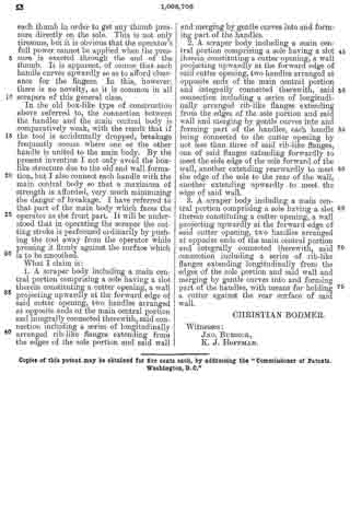
No. 1,201,433 – Plane (Christian Bodmer) (1916)
UNITED STATES PATENT OFFICE.
_________________
CHRISTIAN BODIVIER, OF NEW BRITAIN, CONNECTICUT, ASSIGNOR TO THE STANLEY RULE
AND LEVEL COMPANY, OF NEW BRITAIN, CONNECTICUT, A CORPORATION OF CONNECTICUT.
PLANE.
_________________
1,201,433. Specification of Letters Patent. Patented Oct. 17, 1916.
Application filed June 2, 1916. Serial No. 101,233.
_________________
To all whom it may concern:
Be it known that I, CHRISTIAN BODMER, a citizen of the United States of America, residing at New Britain, Connecticut, have invented a new and useful Plane, of which the following is a specification.
My present invention relates to planes and has for its general objects to provide a practical and inexpensive form of plane which can be used for a number of purposes and which will therefore take the place of a plurality of planes usually employed for such special purposes.
Other objects are to increase the solidity and strength of the same and to make it easily regulatable or adjustable to meet the different conditions.
In the accomplishment of the foregoing and other objects I construct a plane in two parts and mount the cutter blade on the forward end of the rearward section so that when the front part or section is removed the cutter will be left exposed and therefore adapt the rearward section for working in corners, etc. The two sections are rigidly united but so as to permit quick separation of the parts.
A special feature of the invention is the provision of a handle arch on one of the members having a seat or platform with which the other member is engaged, said arch being of reduced width at a point above the cutter seat to accommodate the shank of a cutter and a shank and a cap which has bearing against the under side of the arch.
Other features and details of construction will appear as the specification proceeds.
In the accompanying drawing I have illustrated my invention embodied in a concrete and practical form but it will be understood that changes and modifications may be made without departing from the true spirit and scope of the invention.
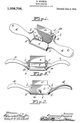
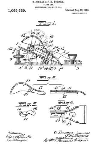
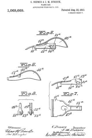
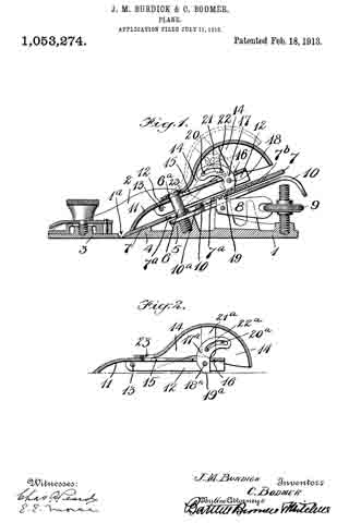
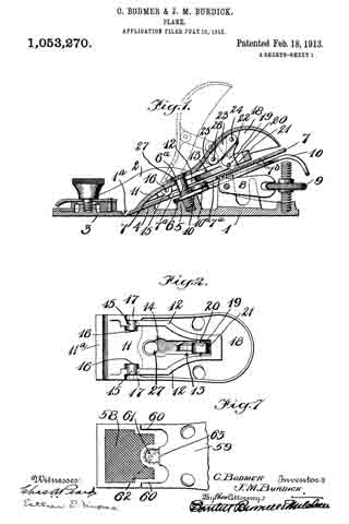
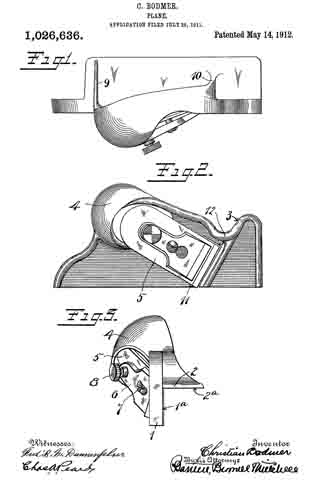
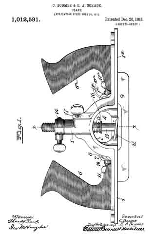
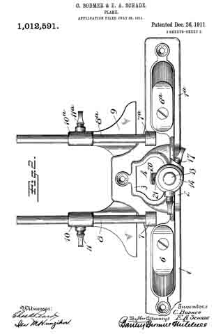
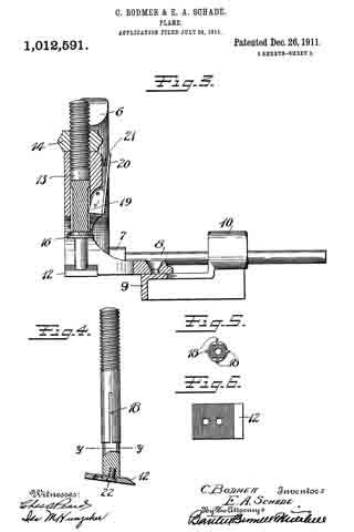
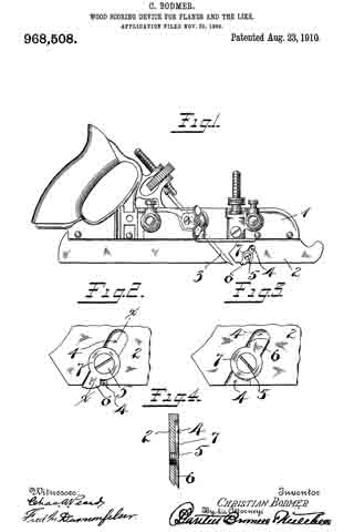
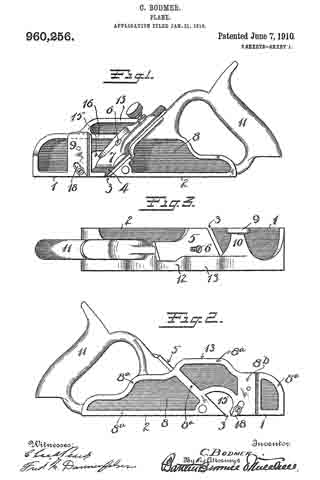
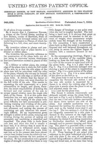
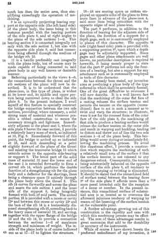
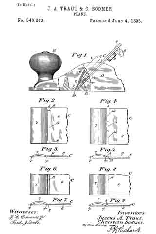
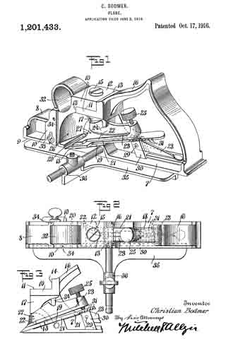
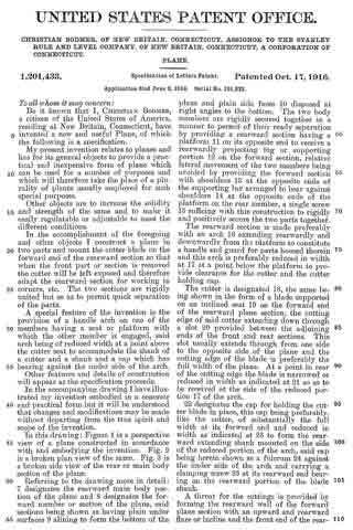
In this drawing: Figure 1 is a perspective view of a plane constructed in accordance with and embodying the invention. Fig. 2 is a broken plan view of the same. Fig. 3 is a broken side view of the rear or main body section of the plane.
Referring to the drawing more in detail: 7 designates the rearward main body portion of the plane and 8 designates the forward member or section of the plane, said sections being shown as having plain under surfaces 9 alining to form the bottom of the plane and plain side faces 10 disposed at right angles to the bottom. The two body members are rigidly secured together in a manner to permit of their ready separation by providing a rearward section having a platform 11 on its opposite end to receive a rearwardly projecting lug or supporting portion 12 on the forward section, relative lateral movement of the two members being avoided by providing the forward section with shoulders 13 at the opposite ends of the supporting lug arranged to bear against shoulders 14 at the opposite ends of the platform on the rear member, a single screw 15 sufficing with this construction to rigidly and positively secure the two parts together.
The rearward section is made preferably with an arch 16 extending rearwardly and downwardly from the platform to constitute a handle and guard for parts housed therein and this arch is preferably reduced in width at 17 at a point below the platform to provide clearance for the cutter and the cutter holding cap.
The cutter is designated 18, the same being shown in the form of a blade supported on an inclined seat 19 on the forward end of the rearward plane section, the cutting edge of said cutter extending down through a slot 20 provided between the adjoining ends of the front and rear sections. This slot usually extends through from one side to the opposite side of the plane and the cutting edge of the blade is preferably the full width of the plane. At a point in rear of the cutting edge the blade is narrowed or reduced in width as indicated at 21 so as to be received at the side of the reduced portion 17 of the arch.
22 designates the cap for holding the cutter blade in place, this cap being preferably, like the cutter, of substantially the full width at its forward end and reduced in width as indicated at 23 to form the rearward extending shank mounted on the side of the reduced portion of the arch, said cap being herein shown as a fulcrum 24 against the under side of the arch and carrying a clamping screw 25 at its rearward end bearing on the rearward portion of the blade shank.
A throat for the cuttings is provided by forming the rearward wall of the forward plane section with an upward and rearward flare or incline and the front end of the rearward section and the top of the cap with rearward flares or inclines 26 and 27 respectively.
Means for adjusting the blade are provided in the illustration and formed with a lever 28 pivoted at 29 on a post 30 mounted in the rear of the cutter seat and engaging the toothed under surface 31 of the cutter blade shank. The use of the plane is facilitated by providing a finger or thumb hold 32 on the forward plane section and this section usually also is provided with a suitable depth gage 33 and spurs 34. The rearward plane section usually mounts a fence 35 carried by an outstanding post 36 which can be attached to either side face of the plane. These several devices enable the tool being used as fillister plane and for various rabbeting purposes and the removal of the depth gage and fence permits of the tool being turned and operated at both sides for working in a corner, a “full width” blade in such cases permitting the tool to work down into the extreme corner.
The front plane section is readily removable and when removed leaves the cutter blade exposed on the front end of the rear section in which case said plane section may be used in the manner of a chisel to work in corners, etc. The general structure of the tool is such that the parts are all rigid and well braced when in use and in addition the structure is relatively simple and inexpensive to manufacture.
What I claim is:
In a plane, a rear body section having a cutter seat at its forward end, a platform above said cutter seat and a handle arch extending rearwardly from said platform to the rear end of the body section, a cutter mounted on the cutter seat, cutter adjusting means on said rear body section within said handle arch and protected thereby, a front body section having a rearwardly extending supporting lug bearing on the platform on the rear body section and a securing screw extending through said supporting lug into engagement with the platform.
CHRISTIAN BODMER.
Copies of this patent may be obtained for five cents each, by addressing the “Commissioner of Patents, Washington, D. C.”
_________________