No. 305,603 – Cabinet-Scraper (John A. Keiser) (1884)

[paiddownloads id=”372″]305603


UNITED STATES PATENT OFFICE.

_________________

JOHN A. KEISER, OF CINCINNATI, OHIO.

CABINET-SCRAPER.

_________________

SPECIFICATION forming part of Letters Patent No. 305,603, dated September 23, 1884.
Application filed June 30, 1884. (No model.)

_________________

To all whom it may concern:

Be it known that I, JOHN A. KEISER, a citizen of the United States,and resident of Cincinnati, in the county of Hamilton and State of Ohio, have invented certain new and useful Improvements in Cabinet-Scrapers, of which the following is a specification, reference being had to the accompanying drawings forming a part hereof.

My invention relates to an improved cabinet-scraper.

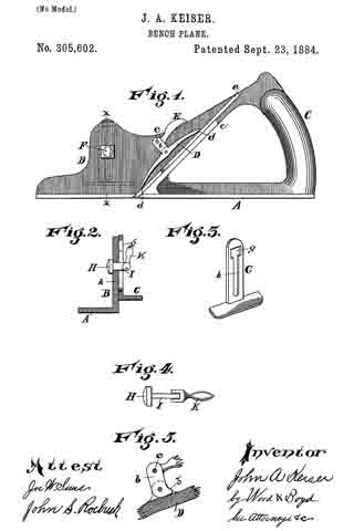
Figure 1 is a top plan view of my improvement. Fig. 2 is a bottom plan view of the same; Fig. 3, a section on line x x, Fig. 1; Fig. 4, a perspective view of the pivoted clamp; Fig. 5, a section on line z z, Fig. 1.

A A’ represent the handle of the scraper. The stock of the tool is composed of the following parts.

B b represent the face of the scraper; C, a slot separating the faces in which the cutter is set.

D represents a ledge, against which the cutter c is clamped. This ledge is rigidly attached to the face B, the parts forming an L, as shown in Fig. 3. F represents the ends of the stock, from which the handles A A’ spring, as shown in Figs. 1 and 2.

E e represent arms forming a part of the end plates of the stock F, for firmly holding face b rigidly in a plane parallel with face B.

G represents a pivotal clamp for clamping the knife c against the ledge D. This clamp is suspended on pivots a to the end plates ofthe stock F, passing through ears d of the clamp G.

H represents a lever-arm extending upward a considerable distance above the pivots of ears d.

I represents a set-screw tapping through the arms H, the point of which bears against the ledge D and forces the lower edge of clamp G against the cutter c at its lower end, and firnily clamps it against D.

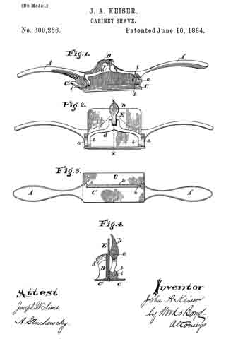
This tool is very cheap, strong, and efficient. The cutter c works clear to the ends of face B b, and is a decided improvement over the tool shown in Letters Patent granted Samuel C. Tatum & Co., my assignees, June 10, 1884, No. 300,266, and other tools for the same purpose hitherto used.

Instead of screw I, a cam may be used to operate the clamp, and would be the equivalent therefor.

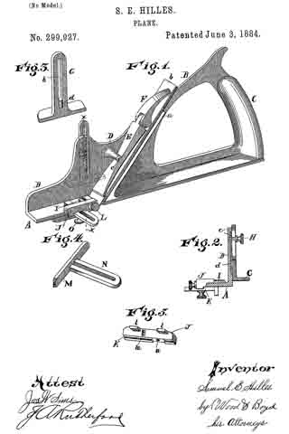
I do not broadly claim a stock having rigid faces separated by a slot, and the front face strengthened by arms forming part of the ends of the stock; nor do I claim, broadly, a cutting-bit attached to an oscillating plate adjustable by a thumb-screw and spring; nor a spokeshave having a bearing-surface in front of the cutter applied by a lever having an adjusting-screw for regulating the width of the month, the thickness of its cut, or the shaving; and I do not broadly claim the bearing-surface of a stock provided with a ledge or flange serving as a bearing for the cutting-bit.

I claim —

1. A cabinet-shave consisting of the stock F, rigid faces B b, separated by slot C, the part b being braced by arms E e, forming part of the end plates of the stock, ledge D, and cutter c, clamped against the ledge, substantially as described.

2. A cabinet-shave consisting of the stock F, rigid faces B b, separated by slot C, ledge D, and clamp G, pivoted to stock F, and adapted to clamp a cutter, c, against the ledge D, substantially as and for the purpose described.

In testimony whereof I have hereunto set my hand.

JNO. A. KEISER.

Witnesses:
MILTON DASHIELL,
SAML. E. HILLES.

No. 305,602 – Bench-Plane (John A. Keiser) (1884)

[paiddownloads id=”371″]305602


UNITED STATES PATENT OFFICE.

_________________

JOHN A. KEISER, OF CINCINNATI, OHIO.

BENCH-PLANE.

_________________

SPECIFICATION forming part of Letters Patent No. 305,602, dated September 23, 1884.
Application filed June 30, 1884. (No model.)

_________________

To all whom it may concern:

Be it known that I, JOHN A. KEISER, a citizen of the United States, and a resident of Cincinnati, in the county of Hamilton and State of Ohio, have invented certain new and useful Improvements in Bench-Planes, of which the following is a specification.

This invention relates to improvements in benoh-planes; and it has for its object to provide novel and efficient means for adjustably connecting the cutter with the plane-stock. This I accomplish in the manner and by the construction and combination of devices hereinafter described and claimed, reference being had to the accompanying drawings, illustrating my invention, in which —

Figure 1 is a side elevation of my improvement. Fig. 2 is a cross-section on line x x, Fig. 1. Fig. 3 is a perspective view of the side gage. Fig. 4 is an enlarged detail view of the side gage and fastening-clamp. Fig. 5 is a detail view of the clamping device.

A represents the base of my plane-stock; B, the side of the stock, G, the handle; c, the ledge on which cutter a rests and is secured.

D represents the cutter-clamp, which is operated as follows:

E represents a bell-crank lever, which is pivoted at e and the side of the stock B.

b represents the arm of bell-crank lever, to which the clamp D is pivotally attached.

b’ represents a shoulder or stop for limiting the pivotal movement of clamp D on arm b, to force the points d down upon the cutter a.

The crank E is made to have two bearing-points, d d. The clamp D is raised and lowered by the movement of the bell-crank lever E. When occupying the position shown in Fig. 1, the clamp D is forced down upon the cutter a, and holds it securely in position. When it is desired to readjust the cutter a, or to take it out, the bell-crank E is lifted up, which moves the points of the clamp away from contact with the cutter a, and allows it to be removed or adjusted.

F represents a mortise or opening pierced through the side of the stock B.

G represents the adjustable side gage, which is provided with a mortise, g, through which is inserted a clamp, and a slot, h, which slides over the shank of the clamp, for allowing the gage G to be adjusted.

H represents a headed clamp-bolt.

I represents the shank of the same, over which the slot h of the gage G moves up or down for its adjustment.

K represents a cam or eccentric lever pivoted to the shank I, which, when turned up, bears against the face of the gage G, securely clamping it in position by drawing the head of clamp-bolt H against the side of the plane-stock, and the cam clamping or pressing against the outside of the gage G. When the lever K is turned down, gage G is released, so that it may be adjusted to the desired height. The mortise g is sufficiently large to allow the eccentric-lever K to pass through the opening g, for the engagement of the slot h, upon the shank I of the clamp-bolt. This device may be readily adjusted and attached to, or removed from the plane. By this method of constructing the side gage the metal of the plane-stock is but slightly weakened, and a very convenient detachable gage is obtained.

I Claim —

In combination with the plane A B, having the ledge c, and the bell-crank E, pivoted to the side of the plane and pivotally connected to the cutter-clamp D, said bell-crank being provided with stop b’, substantially as described.

In testimony whereof I have hereunto set my hand.

JOHN A. KEISER.

Witnesses:
A. GLUCHOWSKY,
A. E. SCOTT.

No. 300,266 – Cabinet-Shave (John A. Keiser) (1884)

[paiddownloads id=”367″]300266


UNITED STATES PATENT OFFICE.

_________________

JOHN A. KEISER, OF CINCINNATI, OHIO, ASSIGNOR TO SAMUEL C. TATUM & CO., OF SAME PLACE.

CABINET-SHAVE.

_________________

SPECIFICATION forming part of Letters Patent No. 300,266, dated June 10, 1884.
Application filed February 28, 1884. (No model.)

_________________

To all whom it may concern:

Be it known that I, JOHN A. KEISER, a citizen of the United States, and a resident of Cincinnati, in the county of Hamilton and State of Ohio, have invented certain new and useful lmprovements in Cabinet-Shaves, of which the following is a specification.

My invention relates to an improved cabinet-shave, and other similar tools.

The object of my invention is to provide ready means for removing or inserting the bit or knife, all of which will be fully set forth in the description of the accompanying drawings.

Figure 1 is a perspective view of my invention with the bit removed. Fig. 2 is a front elevation of my improvement with the bit in position for use. Fig. 3 is a bottom plan view of Fig. 2. Fig. 4: is a vertical section on line x x, Fig. 2.

A A represent the handles of my improved shave.

B represents the central portion of the stock of the shave, which, with the handles, is preferably made of malleable iron, cast in one piece. a represents ears cast on and with the stock B.

C represents the swiveling or detachable bit-face; C’, the stationary bit-face, which forms a part of the stock B.

b represents ears attached to the face C, and provided with pivots i, which hinge the ears b to the ears a.

d represents a yoke or bar connected to the ears b.

The parts C, b, b, and d are made of metal formed in one piece, and arranged so as to more freely upon the pivots i.

D represents a cam connected by pivot c to the center of the yoke d.

E represents the bit or knife, which is made to fit into the head B, as shown in Figs. 2 and 4. In order to hold the knife in position by detachable fastenings, it is essential to have it gripped at two points — first, at or near the cutting edge, and, second, at the central point of the knife, sufficiently near the upper end to prevent its rocking or moving. To accomplish this I provide lugs h, at each end of the cutter E on the bottom of face C, and adapted to bear against the cutter E upon each side of the shaving-slot L.

The mode of operation in inserting the knife is as follows: Fig. 1 represents the device with knife or bit removed from the stock of the shave and the cam D hanging loosely upon the yoke d. The knife E is inserted with the proper feed, (the edge depending below the faces C C’,) and cam D is turned upward so as to bring the shoulder against the face ofthe knife. This movement draws the lugs h, on the face C firmly against the blade E, pressing or gripping it tightly against the face C’ of the stock by the inward movement of the face C, caused by the pressure of the shoulder of cam D against the upper end of the knife, forcing the yoke d outward. This mode of constructing the stock and attaching the parts holds the knife firmly in position, and yet allows it to be instantly inserted and removed.

The principal feature of my invention consists in constructing the pivoted portion of the stock so as to grip the knife near the cutting-edge, and central at or near its upper end, and at the same time not be apt to become accidentally disconnected from its bearings.

An inferior modification of my invention would be to employ a thumb-screw passing through the yoke d, instead of the cam D, for gripping the upper end of the knife E. Such a construction would be covered by the first and second claims herein. Spokeshaves and other tools could be made in a similar manner as the within-described cabinet-shave. Another modification could be made by having the lugs h, attached to the face C’ and the shaving-slot in the same side of the bit-face. So, too, one lug h might be employed near the center of the bit-plane; but it would not be as efficient as the plan here shown.

I claim —

1. A shave composed of the stock B and bit-face C’, in combination with the bit-face C, swiveled by a pintle placed parallel with the axis of rotation of the bit-face, and a fastening device, D, suitably supported, and adapted to grip the bit at or near the top and force one of the bit-faces against the lower edge of the bit, whereby the bit will be held to its place by said fastening D and bit-face, independently of other fastenings, substantially as described.

2. The combination, with the stock B and stationary bit-face C’, of the bit-face C, provided with lugs h to bear against the bit and with yoke d, and swiveled by a pintle parallel with its axis of rotation, and a fastening device, D, connected with the yoke d and adapted to bear against the upper part of the bit, the bit being held to its place by said fastening D and the face C, independently of other fastenings, substantially as described.

3. The combination of the stock B and stationary bit-face C’, provided with ears a, the bit-face C, provided with ears b and yoke d, and swiveled to ears a by pintles i, and the cam-lever D, fulcrumed on yoke d, for instantaneonsly fastening and releasing the bit, substantially as described.

In testimony whereof I have hereunto set my hand.

JOHN A. KEISER.

Witnesses:
EDWARD BOYD,
ANDREW E. SCOTT.

No. 299,927 – Plane (Samuel E. Hilles) (1884)

[paiddownloads id=”366″]299927


UNITED STATES PATENT OFFICE.

_________________

SAMUEL E. HILLES, OF CINCINNATI, OHIO.

PLANE.

_________________

SPECIFICATION forming part of Letters Patent No. 299,927, dated June 3, 1884.
Application filed March 19, 1884. (No model.)

_________________

To all whom it may concern:

Be it known that I, SAMUEL E. HILLES, a citizen of the United States, and a resident of Cincinnati, in the county of Hamilton and State of Ohio, have invented certain new and useful Improvements in Planes, of which the following is a specification.

My invention relates to an improvement in planes.

The object of my invention is, first, to provide suitable attachments for holding the cutter or bit in position; second, to provide improved means for attaching both vertical and side guides to regulate the cutting of grooves, gains, or rabbets.

The invention consists in the novel construction and combination of devices hereinafter described and claimed, reference being had to the accompanying drawings, in which —

Figure 1 is a perspective view of my invention, with the attachments in position for use. Fig. 2 is a central vertical section on line x x, Fig. 1. Fig. 3 is a detail view of the vertical guide; Fig. 4, a perspective view of the side guide; Fig. 5, a detail view of one of the attachments of the side guide.

A B represent an L-shaped plane-stock; C, a handle, the parts being preferably cast in one piece.

a represents a flange upon which the cutter b rests. It is desirable in a plane to provide means for quickly and easily securing the cutter in position, and which can be readily inserted or removed, dispensing with the set-screw, and using instead thereof a cam or eccentric, which bears upon the wide face of the bit or cutter, and holds it more firmly in position than a set-screw, and which can be also more readily set or detached, being more durable than when the cap is secured by screw-threads, which must be formed in the plane-stock, or in the cap, so that common grey iron cannot be practically employed for that purpose.

E represents my improved cap, provided with a lug, e, extending transversely across its upper face, and which engages with the groove formed in the under face of boss D, said groove and lug being arranged across or substantially at right angles to the line of travel of the tool, so that the cap is thereby prevented from longitudinal movement. This lug e and the groove in the face of boss D are rounded or V-shaped, so as to prevent the cap E from being driven downward as the cam-lever F is turned down. A rectangular gain and lug would cause the parts to bind, and not allow the cap E to be raised vertically if the parts are fitted so as to prevent longitudinal motion. The cap E is inserted and removed laterally.

F represents a cam-lever fulcrumed upon the cap E, the face of the cam being as wide as the cutter b, and which when turned down upon the cutter, as shown in Fig. 1, securely holds it in its position on the bed or flange a. The cutter can be loosened, and it, with the cap, quickly removed by turning up the cam F.

G represents a gage or fence, which is secured to the side plate, B, in the following manner:

c represents a vertical groove cut in the face of the side B.

d represents a lug cast on the inner face of the guide G, which engages with the groove c and prevents lateral movement of the guide.

h, represents a slot, pierced through the shank of guide G, through which passes the shank of set-screw H, which taps into the side stock B of the plane, and holds the gage in position. This construction allows the gage G to be adjusted up and down, and secures its adjustment upon the side of stock B without weakening the stock, and in this respect it is an improvement upon the device shown and described in Letters Patent No. 284,941, granted J. M. Bennett, September 11, 1883. The guide G maybe readily removed when it is desired to use the plane with the side B resting against the wood, as in planing into a corner. It is also desirable to provide a side gage, which may be readily attached to or removed from its position on the stock of the plane, and which can be secured thereto in such a manner as not to weaken the stock, which is preferably made of common grey iron. For this purpose I provide a boss, I, on the top face of stock A.

J represents a gage-stock, which is provided with a gain, K, on one of its edges, which gain is of the same width as the side gage, M, so as to allow it to be retracted outward a sufficient distance to employ the full width of the cutter b.

l represents lugs formed upon one side of the gage-stock J, which rests upon the top surface of the stock A, and prevents it from rocking.

L represents a thumb-screw, which is inserted through the gage-stock J, and taps into the boss I, rigidly securing stock J in position to firmly hold the gage M.

n represents a transverse gain cut upon the under surface of the gage-stock J. It is made of the proper shape to receive the slotted shank N, which slides laterally in the gain n, for adjusting the gage M to any desired width of cut.

O represents a set-screw for attaching the gage M to the gage-stock J in such a manner as to adjust the gage, as before described. It will be seen that the gage-stock J and the gage M can be readily attached to or removed from the plane-stock by means of the attaching screw L.

I claim —

1. The combination, in a plane, of the right-angled stock A B, having the flange a, and attached lateral boss D, constructed with a longitudinal groove on its under side, the cap E, having a lug, e, extending transversely across its upper face, and adapted to be slipped sidewise into engagement with the groove of the boss to prevent movement of the cap in the direction of its length, and the swinging cam F, pivoted to the upper end of the cap, for clamping the cutter b upon the flange a substantiallty as described.

2. The combination, with the plane-stock A B, formed with a groove, c, in one side of the part B, but not extending through it, of the adjustable gage G, slotted vertically and provided with the lug d and the set-screw H passed through the slot of the gage and tapped into the part B of the stock, substantially as described.

3. The combination, With the right-angled stock A B, having the boss I on the top face of the part A, of the gage-stock J, provided with lugs l, resting on the face of stock A, and the thumb-nut L inserted through the stock J, and tapped into the boss I to secure stock J in position, substantially as described.

4. The combination of the right-angled stock A B, provided with the boss I on the face of the part A, the gage-stock J, provided with lugs l resting on the face of stock A and , formed with the transverse gain n, and secured to the stock by screw L, the gage M, formed with slotted shank N, entering gain n, and screw O for attaching gage M to stock J substantially as described.

In testimony whereof I have hereunto set my hand.

SAML. E. HILLES.

Witnesses:
ANDREW E. SCOTT,
A. GLUCHOWSKY.

No. 142,216 – Improvement In Planes For Cutting Cigar-Lighters (William H. Drips) (1873)

[paiddownloads id=”215″]142216


UNITED STATES PATENT OFFICE.

_________________

WILLIAM H. DRIPS, OF CINCINNATI, OHIO.

IMPROVEMENT IN PLANES FOR CUTTING CIGAR-LIGHTERS.

_________________

Specification forming part of Letters Patent No. 142,216, dated December 18, 1873; application filed June 24,1873.

_________________

To all whom it may concern:

Be it known that I, WILLIAM H. DRIPS, of Cincinnati, Hamilton county, State of Ohio, have invented a certain new and useful Plane for Cutting Cigar-Lighters, of which the following is a specification:

My invention consists of a small frame, to be placed temporarily upon a table or on the counter of a saloon, cigar-shop, hotel, or other similar place where cigars are sold, the frame containing a fixed plane blade and gage, by means of which the attendant can, with but little labor, make a sufficient number of curled shavings, adapted for cigar-lighters, to form a sufficient stock for the day.

Figure 1 is a general view of my improved tool, showing the method of using my invention. Fig. 2 is a perspective vievv of the tool. Fig. 3 is a plan of the cutter-blade. Fig. 4 is a vertical section of a portion of the frame and cutter-blade.

A is a frame, formed of two strips, A’ A”, of wood, attached at right angles to each other, as shown. The horizontal strip, which rests upon the table or counter, has at one end a lip or flange, a, to engage the edge of the table and prevent it from slipping, said lip being preferably formed in one piece with the strip A’. A cutter-blade, B, of steel, is let obliquely into the plate A’, and secured permanently thereto at each end by screws. Below it is a circular recess, C, which receives the coiled shavings, and allows it to pass out upon the counter. The cutter B is not only let in obliquely in the direction of its length, but is also obliquely located in the direction of its width, so as to cause the shavings to curl anglevvise by its obliquity lengthwise, and cause the knife to present a cutting-edge by its obliquity crosswise. A gage or shield, D, is attached to strip A’ by screws d, the gage being slotted, as shown, to permit adjustment to suit different thicknesses of stud to be cut. This shield prevents the operator’s fingers from touching the knife in the act of pushing the stuff along, in the manner shown, to cut the lighters. The instrument may, however, be made and used without the adjustable gage.

I claim —

As a new article of manufacture, the tool for cutting cigar-lighters, substantially as described.

In testimony of which I hereunto set my hand.

WILLIAM H. DRIPS.

Witnesses:
FRANK MILLWARD,
J. L. WARTMANN.

No. 102,406 – Improvement In Plane-Stock (Julius Katz) (1870)

[paiddownloads id=”164″]102406


United States Patent Office.


JULIUS KATZ, OF CINCINNATI, OHIO.

Letters Patent No. 102,406, dated April 26, 1870.
_________________

IMPROVEMENT IN PLANE-STOCK.

_________________

The Schedule referred to in these Letters Patent and making part of the same.

_________________

To all whom it may concern:

I, JULIUS KATZ, of Cincinati, Hamilton county, Ohio, have invented a new and useful Improvement in Plane-Stocks, of which the following is a specification.

Nature and Objects of the Invention.

My invention relates to an improved facing device for wood-workers’ plane-stocks.

General Description with Reference to the Drawings.

Figure 1 is a perspective under-side view of a plane-stock. embodying my improvement.
Figure 2 is a partly-sectionized side elevation thereof.
Figures 3, 4, and 5 are transverse sections at the lines X X, Y Y, Z Z, respectively.

I make the entire under surface of my improved plane-stock to consist of blocks or strips of bone, ivory, or similar hard organic substance, glued together in two pieces or slabs, A and B, of which the slab A, in rear of the throat C, fits, and occupies a dovetail excavation, D, on the under side of the wooden portion Z of the stock, to which it is firmly glued.

The component strips a and b of either slab are also firmly glued together, and additionally secured together by screws E.

The slab B, instead of being immovably fastened to the stock, is made capable of a slight longitudinal adjustment, and, for this purpose, is surmounted by a bolt or stern, F, which, extending upward through a slot, H, in the plane-stock, is secured by a nut, G, on the top of the stock.

Of the strips which compose the shiftable piece, B, the two outside ones, b’ b’, project rearward from the others, and enter jogs or gains a’ in the slab A.

Claim.

I claim herein as new and of my invention —

Facing a plane-stock with a congeries of strips of bone or like substance, glued and screwed together and fastened to the stock proper in the manner set forth.

In testimony of which invention I hereunto set my hand.

JULIUS KATZ.

Witnesses:
GEO. H. KNIGHT,
JAMES H. LAYMAN.

No. 88,109 – Improvement In Plane-Guide (John Woodville) (1869)

[paiddownloads id=”150″]88109


United States Patent Office.


JOHN WOODVILLE, OF CINCINNATI, OHIO.

Letters Patent No. 88,109, dated March 23, 1869.
_________________

IMPROVEMENT IN PLANE-GUIDE.

_________________

The Schedule referred to in these Letters Patent and making part of the same.

_________________

To all whom it may concern:

Be it known that I, JOHN WOODVILLE, of Cincinnati, in the county of Hamilton, and State of Ohio, have invented a new and useful Improvement in Plane-Guide and Holder; and I do hereby declare that the following is a full, clear, and exact description thereof, which will enable others skilled in the art to make and use the same, reference being had to the accompanying drawings, forming part of this specification, in which —

Figure 1 represents a back-side elevation of my improved apparatus;
Figure 2 represents afront-side elevation, with a part broken away; and
Figure 3 represents a transverse section taken on the line x x of fig. 1.

Similar letters of reference indicate like parts.

The object of this invention is to provide an adjustable holder, or clamp, for holding strips, for dressing them, and which will also serve as a guide for straightening or tapering them. It is designed more particularly to be used with the improved joiners’ plane, patented to me, November 6, 1866.

It consists of a holding-strip, or board, which is designed to be secured to a bench, with one edge upward, and which is provided with an adjustable gauge upon one side, against which the strips to be planed are clamped, by buttons and wedges on the other side of the first-mentioned holding-strip.

A represents the holding-strip, which may be secured to a bench, or in a vise, in any suitable manner, with the edge B upward.

C represents a guide and clamping-strip, which is provided with the T-headed inclined grooves D, whereby it is clamped to the strip A, by the bolts E and thumb-nuts E’; the heads F of the said bolts being arranged loosely thereon, and sliding in the wide part of the grooves D.

The holes through the strips A are elongated, and provided with the hollow bolts I, having enlarged heads arranged in the recesses H. The bolts E pass through these hollow bolts, and the office of the latter is to serve as rigid supports for the former when adjusted to the light position, and screwed up tightly by the nuts I’.

K represents clamping-buttons adjustably connected to the front face of the strip A, by the long bolts L; and

M represents wedges pivoted to the face of the strip A, in a position to be conveniently adjusted under the inclined ends of the buttons, for clamping them against the stuff to be operated upon.

The operation is as follows:

When it is designed to dress a strip with parallel and square edges, the guiding-strip C, which is provided with one edge a, and one bevelled edge b, is adjusted to the strip A, with the square edge a as high above the strip A as the designed width of the strip to be dressed the edge a being in a horizontal plane parallel with the edge of the strip A when it is clamped tight thereto by the bolts E and thumb-nuts E’.

The strip to be dressed is then placed upon the upper edge of the strip A, and clamped between the guide C and the buttons K.

The plane, which, according to the improvements patented to me as above described, is provided with an adjustable guide, d, is then placed upon the strips to be dressed, and held by the said guide, so that the edge e of the stock will project over the guide C sufficiently to arrest the cutting-action of the plane when the strip has been worked down to the point coincident with the edge of the guide C.

Any number of strips may thus be dressed to the same gauge with great uniformity, while at the same time the edges will be exactly square, if the plane-guide be adjusted to that angle.

If it is desired to dress the strips with bevelled edges, the bevelled edge b, of the guide G, is placed upward, as represented in blue lines, at b’; and if it be desired to produce tapered strips, the guide C may be adjusted to produce any taper, by loosening the bolts E and I, so as to allow the plates I to move in the recesses H, to correspond with the varying distances caused between the points of contact with the grooves D, of the heads of the bolts E, by changing the horizontal plane of the guide C.

In dressing thin strips, two or any other number, not wider in the aggregate than the plane-bit, may be clamped together, and dressed at once.

In dressing strips in this manner, in my improved guide and holder, with my improved planes, I have found it very desirable to provide the jack, or roughing-plane with an adjustable gauging-strip, f, as shown in red in fig. 3, for the purpose of arresting the cutting-action of the plane-bit, the amount of a few shavings, before the strips are brought down to a level with the upper edge of the guide C, so that the roughing-plane may be removed in time to finish the work by the jointer, which I provide with a similar guide, d, but not with the guide f

The latter may be adjustably connected to the stock, so that, as the latter wears away, it may be adjusted thereon.

I am aware that clamps have already been arranged upon carpenters’ benches in such a rnanner as to be adjustable for cutting different widths of boards with square or bevelled edges.

Having thus described my invention, I claim as new, and desire to secure by Letters Patent —

1. The combination of the clamping-bolts E and the sliding bolts I, with the supporting-strip A and grooved strip C, whereby said strips are held together, for dressing a board with either parallel or tapering sides, substantially as herein shown and described.

2. The combination, with the strips A and G, of the adjustable buttons K and pivoted wedges M, substantially as and for the purpose set forth.

JOHN WOODVILLE.

Witnesses:
FRANK BLOCKLEY,
ALEX. F. ROBERTS.

No. 59,498 – Improvement In Carpenters’ Planes (John Woodville) (1866)

[paiddownloads id=”120″]59498


UNITED STATES PATENT OFFICE.

_________________

JOHN WOODVILLE, OF CINCINNATI, OHIO.

IMPROVEMENT IN CARPENTERS’ PLANES.

_________________

Specification forming part of Letters Patent No. 59,498, dated November 6, 1866.

_________________

To all whom it may concern:

Be it known that I, JOHN WOODVILLE, of Cincinnati, in the county of Hamilton and State of Ohio, have invented a new and useful Improvement in Jointing-Planes; and I do hereby declare that the following is a full, clear, and exact description thereof, which will enable others skilled in the art to make and use the same, reference being had to the accompanying drawings, forming part of this specification, in which —

Figure 1 is a side view of a plane with my improvement attached. Fig. 2 is a cross-section of the same, taken through the line x x, Fig. 1. Fig. 3 is a detail sectional view of the same, taken through the line y y, Fig. 1.

Similar letters of reference indicate like parts.

My invention has for its object to furnish an improved jointing-plane, by means of which the edge of a board may be made square, or may be beveled at any desired angle; and it consists in the supporting angular plate, the adjustable hinged guide-plate, the adjusting-screw, bush-nut, wrench, and lock-nut, in combination with each other and with the stock or frame of the plane, when said parts are constructed and arranged as hereinafter more fully described.

A is the plane-stock, about the construction of which there is nothing new. B is the supporting-plate, which consists of three portions, b1 b2, and b3. The part b1 is attached to the side of the plane-stock A by two bevel-headed screw-bolts, C and D, which pass through beveled slots E and F in the said part b1 of the plate B, as shown in Fig. 1. The slots E and F are beveled in two ways: first, their edges are beveled so as to fit upon the beveled underside of the heads of the bolts C and D, as shown in Fig. 3, and, second, they are beveled or made wedge-shaped, so as to clamp the bolts C and D, and thus be held securely in place. The rear end of the slot E is enlarged, so as to permit the head of the bolt C to pass through it, but the slot F is cut through the edge of the plate, as shown in Fig. 1. The part b2 stands at right angles to the part b1, as shown in Figs. 1 and 2. The part b3 projects from the upper edge of the part b2, and is parallel with the part b1, as shown in Fig. 2. The part b3 is made in the form of an isosceles triangle, and has a hole made through its apex, which hole is countersunk or rounded out on its upper side, for the purpose hereinafter mentioned.

The plate B is strengthened by having a flange cast upon its edge, as shown in Figs. 1 and 2.

G is the sliding guide-plate, the side edges of which project downward, so as to form ribs or runners g1, upon which it slides along the surface of the timber being operated upon, and insures the plate G from rocking, and gives a steady movement to the plane. g2 and g3 are projecting ears or arms cast upon the plate G, by means of which said plate is pivoted to the plate B. The pivoting-point g4, attached to the ear g3, is made solid therewith; but the pivoting-point g5, attached to the ear g2, is removable, being the point of a screw passing through the said ear, as shown in Fig. 1. These points g4 and g5 enter and work in sockets formed in the edge of the part b2 of the plate B, as shown in Fig. 1.

The ears g2 and g3 are made with a shoulder, as shown in Fig. 2, so that the inner edge of the plate G may be as low or a little lower than the upper corner of the edge of the plane-iron, so that the whole edge of the board may be smoothly cut.

g6 are two ears, cast upon the upper surface of the plate G, between which the end of the screw H is pivoted by a pin passing through the said ears and the said end of the screw, as shown in Fig. 2.

I is a bush-nut, which passes up through the hole in the part b3 of the plate B, before described, and through which the screw H passes. J is a wrench, which fits upon the upper end of the bush-nut I, and which has a feather formed upon its inner surface, which feather enters a slot or groove in the side of the said bush-nut I, so that the said nut may be raised or lowered by turning the wrench J. The nut I is made with a flange on its lower end, and the lower end of the wrench J is rounded off, so as to fit into rounded-out parts of the hole through the plate B at whatever angle the screw H may stand.

K is a lock-nut, which screws down upon the screw H, and locks the wrench J, plate B, and bush-nut I firmly together, the plate B being clamped between wrench J and the flange of the nut I, as shown in Fig. 2.

Into the lower face of the nut K is cut a deep circular groove, as shown in Fig. 2, into the bottom of which is placed a rubber or other elastic spring, L. M is a metal ring, placed in the said groove upon the said spring L. When the nut K is screwed down upon the wrench J the end of the ring M comes in contact with the face of the said wrench J, and holds the parts with an equal pressure at whatever angle the screw H may stand.

By this construction and arrangement the guide plate G may be set at any angle with the face of the plane, so as to give any desired bevel to the jointed edge of the board operated upon, and the parts are all held firm and immovable while the plane is being used, thus insuring a perfectly true joint.

I claim as new and desire to secure by Letters Patent —

The hinged screw-rod H, in combination with the parts D G, and provided with the flanged nut I, wrench J, and lock-nut K, when arranged with the jointing-plane herein described, substantially as and for the purpose specified.

JOHN WOODVILLE.

Witnesses :
ALEXANDER MCDONALD,
THOMAS PALMER, Jr.

No. 56,651 – Improvement In Cabinet-Makers’ Scrapers (Frank A. Williams, John H. Williams And Daniel G. Williams) (1866)

[paiddownloads id=”119″]56651


UNITED STATES PATENT OFFICE.

_________________

FRANK A. WILLIAMS, JOHN H. WILLIAMS, AND DANIEL G. WILLIAMS, OF CINCINNATI, OHIO.

IMPROVEMENT IN CABINET-MAKERS’ SCRAPERS.

_________________

Specification forming part of Letters Patent No. 56,651, dated July 24, 1866.

_________________

To all whom it may concern:

Be it known that we, FRANK A. WLLLIAMS, JOHN H. WILLIAMS, and DANIEL G. WILLIAMS, all of Cincinnati, Hamilton county, Ohio, have invented a new and useful Cabinet-Maker’s Scraper; and we do hereby declare the following to be a full, clear, and exact description thereof, reference being had to the accompanying drawings, making part of this specification.

The scraper in customary use by cabinet-makers, coach-makers, and other finishers of wood-work consists, as is well known, of a simple blade of steel having a turned or upset and sharpened edge. This blade, being grasped by the workman between the fingers and thumbs of both hands is operated by being thrust forcibly over the work. This operation, besides blistering the hands of the operator, so quickly heats up the tool as to soon oblige him to lay it down. These inconveniences we wholly avoid by mounting the scraper proper in a suitably-formed handle of wood or other non-conducting material. We also, in addition to said provision, apply mechanical devices whereby the tool can be made to scrape with greater or less fineness independently of the degree of force or pressure exerted.

Figure 1 is a perspective view of a scraper embodying our invention. Fig. 2 is a transverse section taken at mid-length of the instrument. Fig. 3 shows the parts of the scraper detached. Fig. 4 represents forms of bits adapted for operation on hollow and on round work respectively.

A represents the bit or scraper proper. B is a stock or handle of wood, suitably excavated to receive the bit and a mouth-piece, C.

The bit A, being sprung into the notches b b’, is adjusted toward the mouth-piece, so as to shave with any desired degree of fineness, by means of a set-screw, D.

Thumb-screws E E’ serve to secure the mouth-piece C, and, through it, the bit A.

On slackening of the mouth-piece C by retraction of the screws E E’ the bit is so far released as to be readily shifted, so as to cut rank or fine. When adjusted to cut fine, it should also, by means of the screw D, be set proportionally near to the mouth-piece. On the retraction of the screw D, the spring of the bit itself draws it automatically away from the mouth-piece. The mouth-piece has a throat or excavation, c, through which the shavings escape.

During operation the heads of the thumb-screws E E’ serve as a brace or abutment fbr the thumbs of the operator.

We have selected for illustration a scraper adapted for flat work; but the device is equally applicable for curved work, the bit and handle being modified in each case as judgment or fancy may indicate.

We claim herein as new and of our invention —

A scraper consisting of the blade A, stock B b, mouth-piece C, set-screw D, and clamping-screws E E’, all constructed and arranged substantially as and for the purpose herein specified.

In testimony of which invention we hereunto set our hands.

FRANK A. WVILLIAMS.
A JOHN H. WILLIAMS.
DNL. G. WILLIAMS.

Witnesses:
GEO. H. KNIGHT,
JAMES H. LAYMAN.

No. 14,423 – Plane Stock (John B. Thomas) (1856)

[paiddownloads id=”30″]14423


UNITED STATES PATENT OFFICE.

_________________

JNO. B. THOMAS, OF CINCINNATI, OHIO.

PLANE-STOCK.

_________________

Specification of Letters Patent No. 14,423, dated March 11, 1856.

_________________

To all whom it may concern:

Be it known that I, JOHN B. THOMAS, of the city of Cincinnati, in the county of Hamilton and State of Ohio, have invented a new and useful Improvement in Facing Planes with Glass for Planing Wood; and I do hereby declare that the following is a full and exact description thereof, reference being had to the accompanying drawings, forming part of this specification, and to the letters and figures of reference marked thereon.

Similar letters and figures refer to corresponding parts of the improvement.

The nature of my improvement consists in the means employed for protecting the corners of the glass facing to the plane, by inclosing it within a metal band or case, and holding the glass to the stock of the plane used for carrying the bit.

The improvement is applicable to every description of planes.

To enable others skilled in the art to make and use my improvement I will proceed to describe its construction and operation by referring direct to the accompanying drawings.

Figure A, represents a longitudinal sectional view of the improved plane. Fig. B, is a transverse sectional view of the plane. Fig. C, is a face view of the plane, showing the manner of inclosing the glass face with some metallic substance.

1, represents a case or ferrule into which the glass face 3 is poured, while in a fused or melted state. The lower part of the ferrule is made perfectly true, and placed on a plane or true surface, and the glass face 3, is then poured into it, an opening having been formed by means of a core, or other equivalent, through the glass, for the bit to pass through to the face of the plane, as represented in Fig. A. The glass is held to its place by means of projecting pins or flanges 2, cast or otherwise attached to the inside of the case 1, as represented in Figs. A, and B, thus preventing the glass face from coming out of the case or ferrule, or getting loose.

The stock 4, or upper portion of the plane is made of wood, and employed for carrying the bit 7, and wedge 6, and is connected to the glass face by means of screws 5, passing through the case or ferrule 1, at the ends and sides, as shown in the different drawings, thus firmly uniting the face and stock of the plane, and giving as perfect command over the bit as is had in the ordinary construction of planes.

The glass face will be made from 1/2 to 3/4 of an inch thick, more or less, according to the size and use to which the plane is applied, and the case or ferrule will be made sufficiently wide to firmly unite the stock 4, and face together.

The great advantage arising from the use of a glass face, is in its durability and smoothness, and the plane never becoming untrue on its face or becoming scratched by using the plane on the hardest kinds of woods. The dotted screws represented in Fig. C, extend into the stock 4, of the wood portion of the plane as before mentioned.

Another advantage from the use of my improved plane is the lessening of friction compared with those at present constructed, owing to the smooth surface the glass face will always retain.

What I claim as my improvement and desire to secure by Letters Patent, is —

The glass face 3, combined with the case or ferrule 1, or its equivalent, all substantially as, and for the purposes set forth in the foregoing specifications.

JOHN B. THOMAS.

Witnesses:
L. W. SMITH,
JOSEPH R. DICKEY.