No. 789,255 – Convertible Plane (Sidney C. Carpenter) (1905)

[paiddownloads id=”620″]789255


UNITED STATES PATENT OFFICE.

_________________

SIDNEY C. CARPENTER, OF WEST HARTFORD, CONNECTICUT.

CONVERTIBLE PLANE.

_________________

SPECIFICATION forming part of Letters Patent No. 789,255, dated May 9, 1905.
Application filed September 1, 1904. Serial No. 223,046.

_________________

To all whom it may concern:

Be it known that I, SIDNEY C. CARPENTER, a citizen of the United States, residing at West Hartford, in the county of Hartford and State of Connecticut, have invented certain new and useful Improvements in Convertible Planes; and I do declare the following to be a full, clear, and exact description of the invention, such as will enable others skilled in the art to which it appertains to make and use the same.

My invention relates to convertible planes of that character designed to be used for planing curved or flat surfaces; and the objects of same are to provide a plane with a spring bearing-surface which may be readily and quickly adjusted to the required degree to bear upon surfaces of more or less curvature and which may be readily converted into a plane of the ordinary or usual construction provided with a flat bearing-surface.

Another object is to provide a plane of this character which may be quickly and accurately adjusted for use under varying conditions and which will be provided with means for adjusting cutting-blades or bits relatively, accurately, and quickly.

These and other objects are attained by means of the construction illustrated in the accompanying drawings, in which —

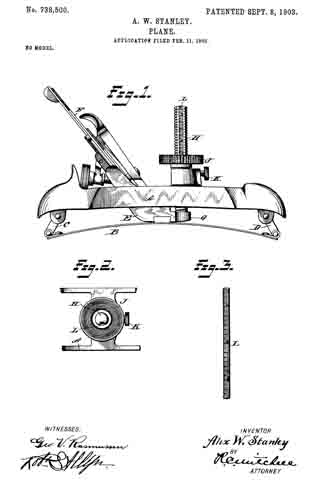
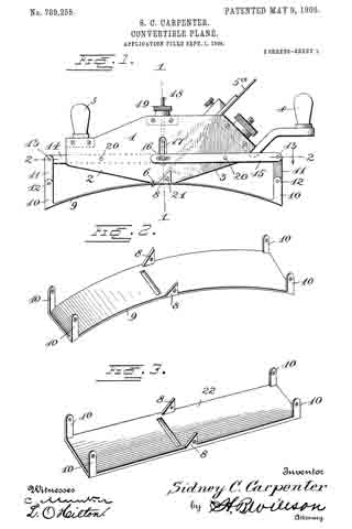
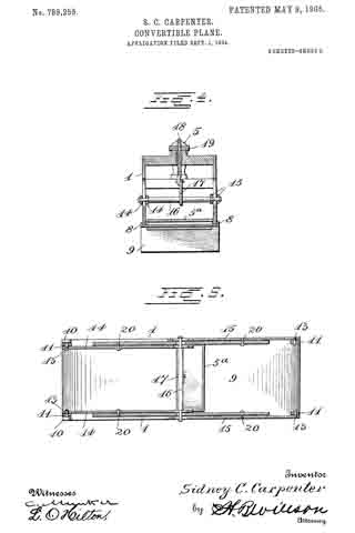
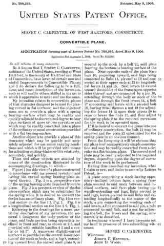
Figure 1 is a side view of a plane constructed in accordance with my present invention and having the curved spring bearing-plate secured thereto. Fig. 2 is a perspective view of the spring bearing-plate detached from the plane. Fig. 3 is a perspective view of the fiat plane-surface which may be substituted for the spring when it is desired to convert the device into an ordinary plane. Fig. 4 is a vertical section on the line 1 1, Fig. 1. Fig. 5 is a longitudinal section on the line 2 2, Fig. 1.

Referring to the drawings for a more particular description of my invention, the numeral 1 designates the body portion of the plane, said body portion being oppositely inclined in front and rear, as shown at 2 3, and provided with suitable handles 4 5 and a cutter or bit 5a. A transverse slightly-curved surface 6 is provided at the central lower portion of the stock or body, and a lug 8, extending upward from the curved steel plate 9, is secured to the stock by a bolt 21, said plate forming the bottom or bearing surface of the plane. Near opposite ends of the plate 9 are lugs 10, projecting upward, said lugs being connected to links 11, pivoted at 12 and connected at their upper ends at 13 to longitudinal levers 14 and 15. Said levers 15 extend toward the middle of the frame upon opposite sides thereof and are connected by a pin 16, extending through the body or stock of the plane and through the front levers 14, a link 17 connecting said levers with a pivoted bolt 18, having fitted thereon a nut 19 for adjusting the levers 14 15 upon their pivots 20 to raise or lower the links 11, and thus adjust the spring-plate 9 to the required curvature for the work to be operated upon.

If it is desired to convert the plane into one of ordinary construction, the bolt 21 may be removed and the plate 22 substituted for the spring-plate in an obvious manner.

From the foregoing it will be obvious that my plane is of comparatively simple construction and may be readily converted from a circular to a flat-bottom plane. The curved steel plate may be readily adjusted to the required degree, depending upon the degree of curvature of the work to be performed.

Having thus described my invention, what I claim as new, and desire to secure by Letters Patent, is —

A plane comprising a stock having oppositely-inclined bottom faces, a spring face-plate secured to said stock between said inclined surfaces, said face-plate having upwardly-extending end lugs, links pivoted to said lugs, levers pivoted to said links and extending longitudinally to the center of the stock, a pin connecting the meeting ends of said levers, a link connected to said pin, a bolt connected to said link, and a nut for adjusting the bolt, the levers and the spring, substantially as described.

In testimony whereof I have hereunto set my hand in presence of two subscribing witnesses.

SIDNEY C. CARPENTER.

Witnesses:
JOSEPH P. KENNEDY,
JOHN D. WOOD.

No. 738,501 – Plane (Alix W. Stanley And Edmund A. Schade) (1903)

[paiddownloads id=”589″]738501


UNITED STATES PATENT OFFICE.

_________________

ALIX W. STANLEY AND EDMUND A. SCHADE, OF NEW BRITAIN, CONNECTICUT,
ASSIGNORS TO STANLEY RULE & LEVEL COMPANY, OF NEW BRITAIN,
CONNECTICUT, A CORPORATION OF CONNECTICUT.

PLANE.

_________________

SPECIFICATION forming part of Letters Patent No. 738,501, dated September 8, 1903.
Application filed February 11, 1903. Serial No. 142,845. (No model.)

_________________

To all whom it may concern:

Be it known that We, ALIX W. STANLEY and EDMUND A. SCHADE, citizens of the United States, residing at New Britain, in the county of Hartford, State of Connecticut, have invented certain new and useful Improvements in Planes, of which the following is a full, clear, and exact description.

This invention relates to planes, and particularly to improvements in the construction of that class of planes adapted to be used on curved surfaces, sometimes called “circular planes.” In planes of this character the base or sole is made flexible, so that it may be bent to any desired curve to cause the plane to fit onto a curved surface, either concave or convex. The sole portion of the plane is usually made of sheet metal, such as spring-steel. It is highly desirable in planes of this character that means be provided whereby the adjustment of the sole to the desired curve may be effected accurately and quickly. To that end, therefore, the main object of this invention is to provide simple and effective mechanism for attaining these results.

In the accompanying drawings, Figure 1 is a side elevation illustrative of a specific embodiment of my invention, the sole of the plane being curved to fit to a concave surface. Fig. 2 is a fragmentary perspective view of detached details of construction.

1 is the main body portion.

2 is the base or sole portion. The sole portion 2 is capable of being curved relatively to the main body portion 1. In the form shown the portion 1 is connected to the middle portion of the sole 2.

3 is the frog, carried by the frame 1 and in turn supporting the plane-iron 4. and the adjustments therefor. It is not necessary to explain in detail the adjustments for the plane-iron, because they are well known and constitute no part of this invention.

5 is a screw-threaded post mounted in a suitable screw-threaded bearing on the forward part of the body 1.

6 is a knob or handle carried by the post 5. When said post is rotated it will move up and down relatively to the body 1.

7 is a telescopic extension of the post 5. The connection between the post 5 and its extension 7 is screw-threaded. The screw-threads on the post which take into the frame 1 are right-hand threads, while the screw-threads on the extension 7 which take into the post are left-hand threads, or vice versa. The post extension 7 is connected to a lever 8 by means of a link 9. The lever 8 is pivotally mounted in the body 1. The link 9 prevents the extension 7 from rotating. The particular screw-threaded adjustment of the post 5 relatively to the frame 1 and the extension 7 relatively to the post 5 produces double the movement of the lower end of the extension 7 that would be produced were the link 7 merely projected into the post 5 without being oppositely screw-threaded. The lever 8 is connected with one end of the sole 2 by means of the link 11. 10 is another lever pivotally mounted in the body 1 and connected to the opposite end of the sole 2 by the link. 12.

15 is a pivot for the lever 8.

16 is a pivot for the lever 10. 13 14 are segmental gears fixed on the pivots 15 16, respectively, so that the movement of one of said levers will be transmitted to the other — for example, the movement of the lever 8 by the aforesaid means will produce a corresponding movement in the lever 10. Hence as the lever 8 is moved upwardly the sole 2 will be curved upwardly. If the lever 8 is moved downwardly, the sole 2 will be curved downwardly, and the position of the levers 8 and 10 and the degree and direction of curvature of the sole 2 are deterininable solely by the handle 6. By means of a suitable indicating device it may be ascertained whether the sole is flat or curved and if curved what degree of curvature exists in the sole. In the particular form shown the indicating device comprises a pointer 17, carried by one of the parts — for example, the body 1 — in such a position as to project into the path of movement of certain graduations carried by another part — for example, the segmental gear 13. Referring to Fig. 1, it will be seen that the pointer 17 projects into a curved slot in the segmental gear 13, adjacent to which curved slot there are certain graduations from zero upward and downward. These graduations indicate degrees of curvature in the sole. When the zero-mark on the graduated scale lies opposite the pointer or line of reading, it indicates that there is no curve in the sole. If any one of the graduations above the zero-mark is brought into line with the pointer, it indicates to the user that the sole is curved upwardly to a certain definite degree. The reverse is true of the graduations below the zero-mark. It might be said that the segmental gear 13 constitutes a movable pointer, which enables the user to accurately set the plane so that the sole will be curved to any desired degree to fit to any particular curved surface, and this adjustment may be accurately and quickly effected without any preliminary trials, such as fitting the plane to the particular curved surface upon which it is desired to operate. When the plane has been set as desired, a set-screw 18 may be operated to clamp the adjusting screw or post 5 and prevent accidental displacement. The set-screw 18 may operate to clamp a split collar on the frame 1, through which the adjusting-post 5 passes.

The subject-matter disclosed and claimed herein is a specific embodiment of the invention broadly claimed in Alix W. Stanley’s application for United States Letters Patent, Serial No. 142,844, filed February 14, 1903.

What is claimed is —

1. A plane for cutting curved surfaces comprising a body portion, a sole portion secured thereto, adjusting-arms pivotally secured to the body portion and connected to the sole portion, segments of gears carried by the pivotal supports, an index or scale carried by one of said segments, and a stationary indicator or pointer carried by the body portion of the plane coacting with the scale or index whereby the degree of curvature of the sole portion may be indicated.

2. A plane comprising a body portion, a flexible sole portion secured thereto, a pair of arms pivoted in said body portion and connected to the ends of the sole portion, an index or scale carried by one of said arms, and a relatively stationary indicating member carried by the body portion of the plane and coacting with the scale or index for indicating the degree of curvature.

3. A plane for cutting curved surfaces comprising a body portion, a sole portion secured thereto, a pair of arms pivoted to the body portion and connected to the sole portion, gear-segments mounted to operate with said arms, one of said segments being slotted and having a scale or index adjacent the slotted portion, and an indicating member carried by the body portion of the plane cooperating with the scale or index for the purpose specified.

Signed at New Britain, Connecticut, this 7th day of February, 1903.

ALIX W. STANLEY.
EDMUND A. SCHADE.

Witnesses:
ROBERT N. PECK,
WILLIAM J. WORAM.

No. 738,500 – Plane (Alix W. Stanley) (1903)

[paiddownloads id=”588″]738500


UNITED STATES PATENT OFFICE.

_________________

ALIX W. STANLEY, OF NEW BRITAIN, CONNECTICUT, ASSIGNOR TO
STANLEY RULE & LEVEL COMPANY, OF NEW BRITAIN,
CONNECTICUT, A CORPORATION OF CONNECTICUT.

PLANE.

_________________

SPECIFICATION forming part of Letters Patent No. 738,500, dated September 8, 1903.
Application filed February 11, 1903. Serial No. 142,844. (No model.)

_________________

To all whom it may concern:

Be it known that I, ALIX W. STANLEY, a citizen of the United States, residing at New Britain, in the county of Hartford, State of Connecticut, have invented certain new and useful Improvements in Planes, of which the following is a full, clear, and exact description.

My invention relates to planes, and particularly to that class of planes adapted to be used on curved surfaces, sometimes termed “circular planes.” In planes of this character the base or sole portion is so arranged that it maybe made to assume different curvatures to cause the plane to properly fit to surfaces of different degrees of curvature upon which it is desired to operate the tool. These curvatures may be either concaved or convex. In the particular form shown the sole or base is made of flexible material, such as sheet metal or spring-steel. When adjusting the sole to the desired curvature, it is most desirable that said adjustment may be effected accurately and quickly.

To that end, therefore, the object of my invention is to provide simple, effective, and durable means whereby the plane may be so adjusted that exactly the proper curvature will be given to the sole without requiring the user to make any preliminary trials to ascertain whether the plane fits the curved surface on which it is to be used.

Figure 1 is a side elevation illustrative of one particular embodiment of my invention, the sole of the plane being curved to operate on a convex surface. Fig. 2 is a fragmentary plan view of the setting and reading mechanism. Fig. 3 is a perspective view of the scale.

A is a frame or main body, perfectly rigid.

B is a base or sole, which may be made of any flexible material, preferably spring sheet-steel.

C D are links located at the ends of the sole and in the particular form shown connected with the ends of the frame A.

E is a frog connected with the sole B and supporting the plane-iron F and the adjustments therefor, which latter need not be explained, because they constitute no part of this invention.

H is a post connected with the frog E. In the particular form shown the post H passes up through a portion of the body A, and on the post is mounted a screw-threaded adjusting device J in the form of a thumb-nut. This thumb-nut is rotatable in the body A, but is held against longitudinal movement. Hence when this thumb-nut is rotated the post H is moved up or down to produce a curvature of the sole B.

K is a screw by the rotation of which the thumb-nut J may set at any desired position to lock the adjusted parts against accidental displacement. In the form shown one side of the post H is flattened and upon said flattened surface is a graduated scale L. The graduations may, however, be formed upon the post itself. This scale runs from zero upward and downward, the graduations being proper to indicate to the user the exact curvature of the sole. These graduations are read on the line of the upper surface of the thumb-nut J, since that member is relatively stationary and its upper surface constitutes a convenient indicating-line. The zero-mark when registering with the indicating line means to the user that the sole is flat and not curved either upwardly or downwardly. If the thumb-nut J is so turned as to raise the post H, the graduation thereon adjacent the indicating-line indicates to the user the curvature of the sole. In Fig. 1 the zero-mark will be seen to be above the indicating-line. Hence the sole is curved upwardly, so that the plane may be used on a convex surface. Were the post depressed, so that some graduation above the zero-mark should lie adjacent to the indicating-line, it would show to the user that the sole is curved downwardly. The particular graduation would indicate to him the exact curvature of the sole.

The construction as a whole is simple and reliable and facilitates the accurate and quick adjustment of the sole to any definite curvature without the necessity of making any preliminary trials.

It is apparent that the plane herein specifically shown and described is capable of modification without departing from the spirit or scope of the invention.

Another specific embodiment of this broad invention is shown in a companion application, Serial No. 142,845, filed February 14, 1903.

What is claimed is —

1. A plane for operating on curved surfaces comprising a relatively stationary frame or body portion, a flexible sole portion secured thereto, an adjusting post or screw coacting with the flexible sole portion, and the relatively stationary body portion, a scale or index carried by the adjusting post or screw and a relatively stationary indicating member coacting with the post for the purpose of determining the change of curvature of the sole portion as indicated by the scale, said indicating member having a rotative movement relatively to said body.

2. A tool for planing curved surfaces comprising a relatively stationary body portion, a flexible sole portion carried thereby and movable relatively to the body portion, an adjustable scale-carrying member movable with the sole portion, and a relatively stationary indicating member carried by the body portion cooperating with the scale portion whereby the relative positions of the body and sole portions of the plane may be measured, said scale having graduations running upward and downward from zero.

3. A plane for curved surfaces comprising a body portion, a relatively movable and flexible sole portion pivotally mounted with respect thereto, an adjusting-screw operating in the body portion and cooperating with the sole portion, a scale or index carried by said screw, an adjusting-nut operating on said screw and in conjunction with the body portion, one edge of the adjusting-nut being adapted to act as a pointer or indicating member in conjunction with the scale for determining the relative positions of the body and sole portions.

Signed at New Britain, Connecticut, this 7th day of February, 1903.

ALIX W. STANLEY.

Witnesses:
ROBERT N. PECK,
WILLIAM J. WORAM.