No. 334,324 – Plane (John Woods) (1886)

No. 334,324 – Plane (John Woods) (1886)

[paiddownloads id=”403″]334324


UNITED STATES PATENT OFFICE.

_________________

JOHN WOODS, OF COLUMBIA, TENNESSEE.

PLANE.

_________________

SPECIFICATION forming part of Letters Patent No. 334,324, dated January 12, 1886.
Application filed May 16, 1885. Serial No. 165,739. (No model.)

_________________

To all whom it may concern:

Be it known that I, JOHN WOODS, a citizen of the United States, residing at Columbia, in the county of Maury and State of Tennessee, have invented certain new and useful Improvements in Planes, of which the following is a specification.

This invention relates to improvements in planes; and it consists in certain improved constructions and means for adjusting the knife or cutter-blade, whereby the proper adjustment may be made with facility and precision, all as will be hereinafter described, and particularly pointed out in the claim.

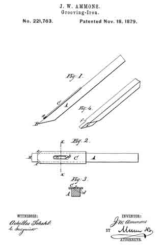
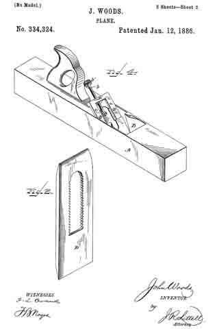
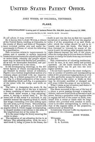
In the accompanying drawings, in the different figures of which corresponding parts are denoted by similar letters of reference, Figure 1 is a vertical longitudinal section of a common plane provided with my improvement; Fig. 2, a detail perspective of the cutter; Fig. 3, a detail perspective of the removable adjusting-block, and Fig. 4 a perspective of the plane with the wedge and knife removed.

The letter A designates the stock; B, the usual box. At the end of the box is secured a frame consisting of bars a and cross-bar a’, into which latter screws a long adjusting-screw, b, having a milled head, b’. To the lower end of this screw b is swiveled in any suitable manner the adjusting-block C, which has wings c extending over and sliding upon the side arms, a, of the frame. This adjusting-block also has a projection, d, formed with angular sides d’, which engage correspondingly-shaped notches or serrations in the sides of the longitudinal slot of the cutter D.

E is the usual wedge for firmly securing the cutter in place.

The operation of my adjusting device is as follows: The adjusting-screw, with its swiveled block C, being in place in the frame, the knife is put into the box so that two opposite serrations or notches will fit over the angular sides d’ of the projections d on said block, after which the wedge should be put in to loosely rest upon the blade. The blade is then elevated or lowered, by means of the screw b, until its cutting edge projects just the right distance beyond the sole of the plane, when the wedge may be driven down to further secure or clamp the blade from any movement in the box.

This construction of adjusting mechanism, it will be seen, is at once easily and quickly operated. As the blade becomes worn, the adjusting-block can be put into the next higher notches.

I do not limit myself to the exact configuration or number of notches and corresponding sides of the projections engaging them, or even to this particular means for securing the adjusting-block to the cutter or blade, as they may be obviously modified or changed and still come within the scope of my invention.

What I claim as my invention, and desire to secure by Letters Patent, is —

The frame mounted in the rear of the box of a plane, a screw passing through a cross-bar therein, and a swiveled block on the end of said screw, having a projection with angular sides to engage the slot in the cutter or knife, combined with a cutter or blade with its longitudinal slot provided with notches or serrations in its sides corresponding in outline to that of the angular sides of the projection, substantially as described.

In testimony whereof I affix my signature in presence of two witnesses.

JOHN VVOODS.

Witnesses:
Z. WATTS,
G. A. LANIER.

No. 221,763 – Improvement In Grooving-Irons (John W. Ammons) (1879)

[paiddownloads id=”306″]221763


UNITED STATES PATENT OFFICE.

_________________

JOHN W. AMMONS, OF COLUMBIA, MISSOURI, ASSIGNOR TO HIMSELF AND JOHN P. HORNER, OF SAME PLACE.

IMPROVEMENT IN GROOVING-IRONS.

_________________

Specification forming part of Letters Patent No. 221,763, dated November 18, 1879; application filed September 15, 1879.

_________________

To all whom it may concern:

Be it known that I, JOHN W. AMMONS, of Columbia, in the county of Boone and State of Missouri, have invented a new and Improved Grooving-Iron, of which the following is a specification.

My invention relates to improvements in the tongued irons or bits used in grooving-planes.

Heretofore the form of these irons has been such as to leave the corners of the groove sharp. This is objectionable on account of their liability to break off when the tongue is forced in and carried back into the groove, whence they have to be removed at a great expense of time and trouble; or if allowed to remain they interfere with the making of a good joint. To prevent this with the present tools, it is the habit of many workmen to chamfer off the corners with an ordinary rabbeting-plane; but this requires the use of another tool and the expenditure of valuable time.

The object of my invention is to provide a plane-iron which will chamfer off the outer corners of the groove simultaneously with the planing of the groove.

The invention consists in a plate with beveled cutting-edges, a slot, and a longitudinal groove, in combination with a grooving-iron provided with a cutting-edge, as hereinafter described.

In the accompanying drawings, Figure 1 is a side elevation of my improved iron. Fig. 2 is a plan view of the same. Fig. 3 is a cross-section on line x x of Fig. 2; and Fig. 4 represents, in perspective, a modified construction of the iron.

Similar letters of reference indicate corresponding parts.

Referring to the drawings, A is the grooving bit or iron, made of a rectangular bar of steel, with cutting-edge B. On the upper side of iron A is placed a flat plate of steel, C, which is secured to the bit by a set-screw, b, passed down through the slot c in the plate into a threaded hole in the bit.

In the under side of the plate is a shallow longitudinal groove, d, sufliciently wide to receive the bit, as shown in Fig. 3. This groove d, together with the set-screw b, connects the plate C rigidly with the bit A, so that the plate C can neither rise nor lose its parallel adjustment with relation to the bit.

At the lower end of plate C the corners are chamfered or beveled off at any suitable angle, and the corners are given sharp cutting-edges e e.

The plate C is designed to extend one-sixteenth of an inch beyond the sides of the bit, so that the angular cutting-edges e e will come in contact with the sides of the groove cut by the bit. The object of this arrangement is to chamfer off the upper corners of the sides of the grooves at the same time the groove is planed, so as to enable the flooring-tongue to be entered into the groove without trouble, and without liability of breaking off the corners of the groove and forcing the splinters in the groove, as before mentioned.

The lower end of plate C forms the shoulders of the plane-iron to limit the depth of the groove.

In Fig. 4 is shown a bit with the shoulders forming a part thereof, in the usual manner. Herein the front lower edges, f f, are cut off at an angle and sharpened to an edge, the same as the edges e e of the plate C.

Both forms of plane-irons operate in the same way to chamfer off the corners of the sides of the groove; but the arrangement first described offers superior facilities for keeping the bit in good order, on account of the ease with which the edges e e can be sharpened.

Having thus fully described my invention, I claim as new and desire to secure by Letters Patent —

The plate C, having beveled cutting-edges e e at a suitable angle, and provided with a longitudinal groove, d, and slot c, and set-screw b, in combination with the grooving-iron having cutting-edge B, for the purpose of chamfering off the corners of the sides of the grooves, substantially as described.

JOHN W. AMMONS.

Witnesses:
F. D. EVANS,
I. O. HOCKADAY.