No. 275,539 – Bench-Plane (Levi Culver Strong) (1883)

[paiddownloads id=”33″]275539


UNITED STATES PATENT OFFICE.

_________________

LEVI C. STRONG, OF ALBANY, NEW YORK, ASSIGNOR OF THREE-FOURTHS TO PETER KINNEAR AND CHARLES H. TURNER, BOTH OF SAME PLACE.

BENCH-PLANE.

_________________

SPECIFICATION forming part of Letters Patent No. 275,539, dated April 10, 1883.
Application filed July 15, 1882. (No model.)

_________________

To all whom it may concern:

Be it known that I, LEVI CULVER STRONG, a citizen of the United States, residing at Albany, in the county of Albany and State of New York, have invented new and useful Improvements in Combination Bench-Planes, of which the following is a specification.

I have produced an improved combination-plane for carpenters’ use, in which the stock is adapted for attachments for doing a variety of work, such as tonguing and grooving, beading, rabbeting, and various shapes of moldings, which meet all the requirements of the work in being interchangeable with the stock, giving all the conveniences of the separate and expensive styles of planes generally used for different styles of work.

In my improved plane the blade of the stock, which has heretofore been made integral therewith, constitutes the attachable and detachable form or mold corresponding with the form of the cutter used for the desired work, and which have heretofore been used as separate attachments to the stock-blade. A simple and effective fastening is provided for these interchangeable form-blades, whereby they are easily and quickly attached and detached from the stock, and rendered firm in such attachment. Each form-blade has a stem at or near the middle of its length, extending up from its top, and the stock has a socket adapted to receive the stem of each form-blade, and a thumb-screw for binding the stem within said socket, while grooves, recesses, or sockets serve to receive the upper corners of the form-blades to hold and brace them in line with the stock. The stem also serves to brace the form-blades laterally, so that the grooves, recesses, or sockets in the bottom of the stock need only be deep enough to lock the form-blades in line with the stock.

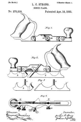
The particular matters which distinguish my plane from others will be made the subject of specific claims, and are illustrated in the accompanying drawings, in which —

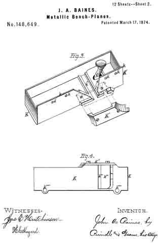
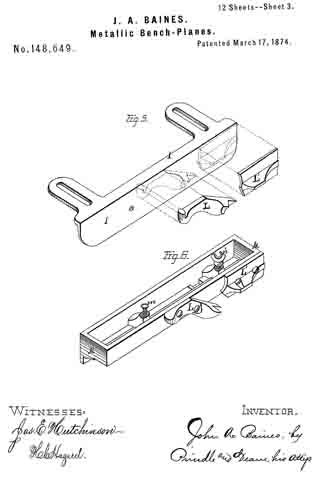
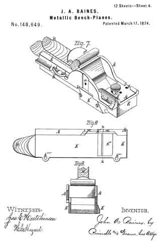
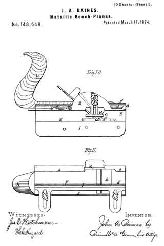
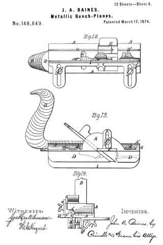
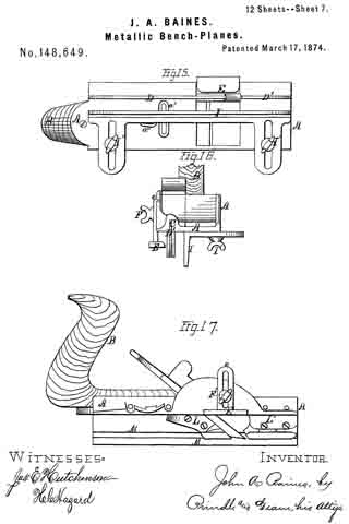
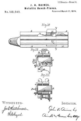
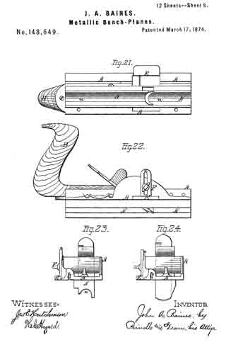
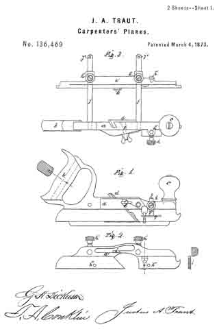
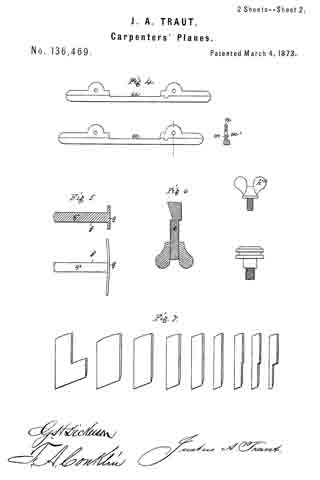
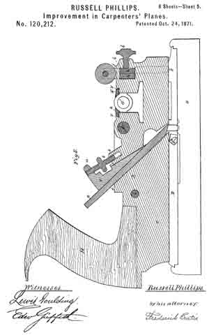
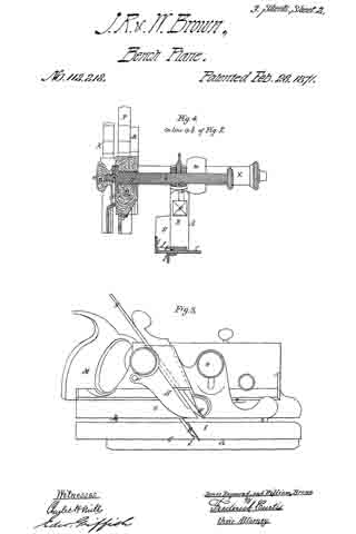
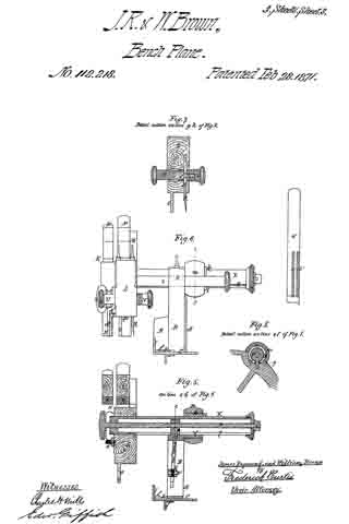
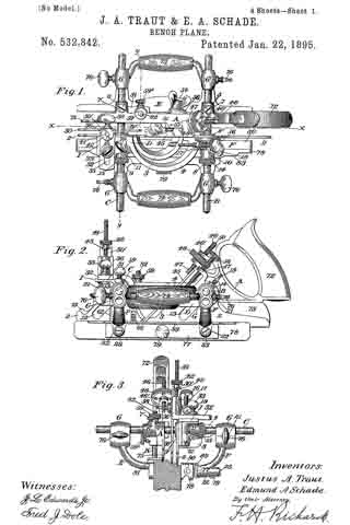
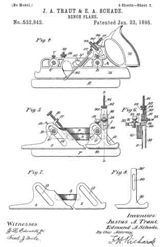
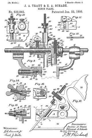
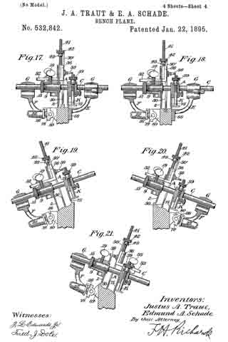
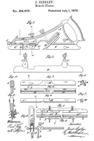
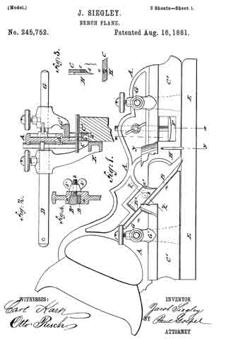
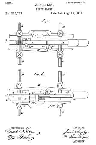
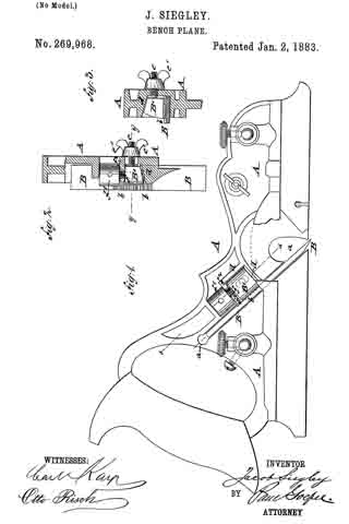
Figure 1 represents a side elevation of the stock of my improved combination-plane, showing the screws for clamping the interchangeable form-blades in the sockets thereof. Fig. 2 represents a similar view, showing the plow-blade clamped to the stock; Fig. 3, the two sections of the plow-blade or runner detached from the stock; Fig. 4, a bottom view of the stock, showing the sockets for the blade-stems; Fig. 5, a bottom view of the plane, with attachments for use as a plow, a dado, and a fillister or rabbet plane; Fig. 6, a cross-section of the same, taken on the line x x of Fig. 5; Fig. 7, a similar cross-section, showing the plane with a blade-form adapted for fluting or coving; Fig. 8, a similar section, showing the plane with a blade-form adapted for tonguing and grooving or matching. Fig. 9 shows a section of a blade-form for beading; Fig. 10, a perspective of the skeleton blade-form; and Fig. 11 shows blade-forms for hollows.

The stock is of metal, and has the usual handle, front knob, and middle inclined bearing or back for the bit, upon which it is secured by a bolt having an inclined side or wedge face passing horizontally through the stock, and adapted to clamp the knife-blade upon its inclined seat, in the manner shown and well known in bench-planes.

Hitherto metallic stocks of convertible bench-planes have been provided with attachable and detachable forms or molds of various shapes applied thereto as face-plates or runner-soles, in connection with cutters of corresponding form for performing a variety of work; but by my improvement the forms constitute also the blade of the stock.

The stock is formed with a vertical socket, a, about midway between the knife-bearing and each end, and the form and the runner blades b have each a stem, c, on their upper edges, at or about the middle of its length, adapted to fit into said socket. The form-blades are of two sections, and the front end of the rear section forms a continuation of the inclined knife-bearing. It is secured to the stock by a clamp-screw, d, at its outer side, which is enlarged by boss projections, screw-tapped, to receive the clamping-screws. This gives a secure and convenient fastening for the form-blades, and braces them laterally to the stock. To prevent the blades from turning upon the stem as a pivot, the stock has grooves, recesses, or sockets e in its under side, into which the upper corners, e’ e’, of the form-blades are inserted, and thereby lock the blades in line with the stock. Both form-blades are fastened in the same manner-one in front, and the other behind the bit — and the stock may have a shallow groove to receive the upper corners; but a continuous groove in the stock is not necessary, as the form-blades may have two or more vertical stems entering corresponding sockets in the stock to keep them in line therewith, as the middle stems and the clamp-screws form the fastening for the interchangeable form-blades. Of Whatever form of blade used, it is secured by the same means directly to the stock, and its sole or runner part b’ must correspond with the form of the cutter, and projects on the working side of the plane.

For plowing, rabbeting, fillistering, and dadoing, form-blades are not used, but blades as mere runners, as shown in Figs. 2 and 3, fastened, however, in the same manner as the form-blades.

The stock is provided with the usual horizontal detachable arms, screwed into the stock on each side of the bit, for receiving the supplemental stock e and the fence f which are used according to the character of the work, and made adjustable upon the arms.

The form-blades and the runner-blades extend equal distances from the bottom of the stock, and the fence is constructed so as to be set beneath the form and the runner blades when used without the supplemental stock. For this purpose the fence is carried by curved arms g in such manner that its upper edge will be at a level to allow it to be set so that its guide-face may come in vertical plane of the outer side or face of the blade of the form parts or of the runner, or in any intermediate positions, as shown in Figs. 7, 8, and 9. This gives the advantage of producing fluting or a cove, as in Fig. 7, or an edge or a center bead, as in Fig. 9, by the proper adjustment of the fence and the gage h, which is secured to the stock by a vertical stem and clamp-screw in the usual manner. This adaptation of the fence for adjustment beneath the form-blades and the runner gives a greater variety of work with a less number of attachments, which would otherwise be required with a fence of the usual construction.

The form-blade has an open or skeleton base or running surface, b’, and the blade part, b, proper is scalloped between its fastening stem and ends, which is important in reducing their weight to a minimum and lessening the friction.

I claim —

1. The combination of the stock provided with the vertical sockets a a and the bottom groove or recesses, e e, with the form or the runner blade b, having a vertical central stem, c, and end locking bearings, e’ e’, and the clamping-screws d d, tapped into the side of the stock, substantially as described, for the purpose specified.

2. In a combination bench-plane, the form-blades thereof, having an open or skeleton form surface and a vertical blade-stem, and adapted for attachment to a stock provided with vertical sockets, substantially as described.

3. In a combination bench-plane, the form and runner blades thereof, having each a vertical stem on its upper edge at or near the middle of its length, in combination with a stock having vertical sockets for said stems, and means, substantially as described, for fastening said stems to the stock, substantially as described.

4. The bench-plane herein described, consisting of the metal stock having the vertical sockets a a, the side screw-tapped holes entering said sockets at right angles thereto, and a bottom groove or recess, e, the form or runner blades b b’, having each a vertical stem, c, and corners e’ e’, and the screws d d, all constructed fer use substantially as herein set forth.

In testimony whereof I have hereunto set my hand in the presence of two subscribing witnesses.

LEVI CULVER STRONG.

Witnesses:
A. E. H. JOHNSON,
J. W. HAMILTON JOHNSON.

No. 230,088 – Bench-Plane (William T. Wainwright) (1880)

[paiddownloads id=”309″]230088


UNITED STATES PATENT OFFICE.

_________________

WILLIAM T. WAINWRIGHT, OF DRY SAWMILL, PENNSYLVANIA.

BENCH-PLANE.

_________________

SPECIFICATION forming part of Letters Patent No. 230,088, dated July 13, 1880.
Application filed April 28, 1880. (No model.)

_________________

To all whom it may concern:

Be it known that I, WILLIAM T. WAINWRIGHT, of Dry Sawmill, in the county of Elk and State of Pennsylvania, have invented a new and useful Improvement in Planes, of which the following is a specification.

My invention consists in certain novel details of construction and arrangement of parts, whereby the same tool may be used for square-jointing, for beveling, and for rabbeting, as hereinafter particularly described.

In the accompanying drawings, Figure 1 is a side view of a plane embodying my improvements. Fig. 2 is a top view of the same. Fig. 3 is a transverse vertical section taken in the line x x of Fig. 2. Fig. 5 is a transverse vertical section taken in the line y y of Fig. 2. Figs. 4. and 6 are views hereinafter referred to. Figs. 7, 8, 9, and 10 are views of grooving and tonguing attachments as applied to my plane, hereinafter referred to.

Similar letters of reference indicate corresponding parts.

The plane A, bit B, and handle C may be of the usual or any suitable description.

To the front end of the plane is attached (see Fig. 3) a block, D, which slides on tongue-and-groove dovetail ways arranged longitudinally of the plane, and may be adjusted nearer to or farther from the bit B, in order to regulate the size of the throat, by means of a thumb-screw, E, working through a standard, e, attached to the block D, and engaging with an internally-threaded standard, f attached to the plane A, and passing through a slot in the block.

To the left-hand side of the plane is hinged a bar, G, composed of two pieces connected by pins g. One end of each pin is fast to one of the pieces, and the remainder of its length is arranged to slide in a hole in the other piece transversely to a set-screw, lt, the point of which bears against the pin. By this means the bar may be widened or narrowed, to accommodate work of different widths.

To the plane A are attached two pairs of perforated lugs, i i, i i, which form bearings for lateral gudgeons extending from one end of each of two pins, K K, the remaining portion of each of which slides in a globe, l, provided with lateral gudgeons having their bearings in perforated lugs m, arranged in pairs and attached to the bar G, and each provided with a thumb-screw, N, the point of which bears against the pin K. By this means the bar G may be adjusted at an angle with relation to the plane, as shown in Fig. 5, so as to plane a bevel, as shown in Fig. 6 of the drawings, or may be adusted at any other suitable angle; and when not in use it may be folded under the plane, as shown in Fig. 3.

On the right-hand side of the plane (see Fig. 3) is a recess, in which works a cutting-blade, P, regulated by a thumb-screw, Q, working in the handle C. On the outer side of the handle is a slotted gage, B, provided with a thumb-screw, S. By means of this cutting-blade P and the plane-bit B a rabbet (such as is shown in Fig. 4) may be cut, and the depth of cut is regulated by the gage R and screw S.

Figs. 7, 8, 9, and 10 represent an attachment for making tongues and grooves. It consists of a bar, T, attached to the plane A by screw-bolts T2, provided with heads t.

The bar T carries a tonguing-bit, U, which may be changed for a grooving-bit. Both of said bits are held in place by a thumb-screw, u, which passes through a slot in the shank of a cutting-bit, V, provided with a thumb-screw, v, for adjusting it.

The bit V is intended to make a cut parallel with the line of travel of the tonguing or grooving bit and co-operate with said bit in removing the shavings. When this attachment is not in use it may be removed and laid aside by unscrewing the bolts T2.

Having thus described my invention, I claim as new and desire to secure by Letters Patent —

1. The combination, with the plane A, of the hinged bar G, lugs i and m, pins K, globes l, and screws N, fbr adjusting the plane for beveling, as herein shown and described.

2. The combination, with the plane A, of the rabbet-cutting blade P, screw Q, gage R, and screw S, as herein shown and described.

WM. TYLER WAINWRIGHT.

Witnesses:
GEORGE A. JOHNSON,
JOHN WAINWRIGHT.

No. 206,507 – Improvement In Bench-Planes (Justus A. Traut) (1878)

[paiddownloads id=”293″]206507


UNITED STATES PATENT OFFICE.

_________________

JUSTUS A. TRAUT, OF NEW BRITAIN, CONNECTICUT.

IMPROVEMENT IN BENCH-PLANES.

_________________

Specification forming part of Letters Patent No. 206,507, dated July 30, 1878; application filed June 3, 1878.

_________________

To all whom it may concern:

Be it known that I, JUSTUS A. TRAUT, of New Britain, in the county of Hartford and State of Connecticut, have invented certain new and useful Improvements in Planes, of which the following is a specification:

The invention relates to that class of small planes known as “rounds,” “hollows,” “beading-planes,” &c.; and the invention has for its object the production of this class of planes in iron, whereby they are more durable and as cheap or cheaper than wooden ones, and also to make one or two handles and frames answer for many stocks or for a complete set, whereby they are less expensive and occupy less space for storage than those heretofore made.

My invention consists, first, of a plane handle and frame, having a longitudinal rabbet and provided with clamping mechanism, in combination with a separately-formed plane-stock and its cutter, adapted when united to be readily attached and detached to the side of said frame, as hereinafter described; and, second, in the particular clamping mechanism, as hereinafter described.

In the accompanying drawing, Figure 1 is a side elevation of a plane which embodies my invention. Fig. 2 is a side elevation of the plane-stock detached; and Fig. 3 is a vertical section on line x x of Fig. 1.

A designates the handle, and B its frame, the latter having two depending lugs, a. (Indicated by broken lines in Fig. 1, and one of which is shown in Fig. 3.) These lugs are off-set a little from the body of the frame, so as to form a longitudinal rabbet to receive the stock C.

b b designate lever-nuts on the ends of screws c, which pass through the lugs a. These screws are made with a coarse thread on one end and a fine thread on the largest end, which is screwed into the lugs, the same fitting snugly, so as not to be easily rotated therein.

The bed e of the stock C may be of any desired form for any of the ordinary small planes — as, for instance, the round-bottom, as shown in Figs. 1 and 3, or the hollowing bottom.
(Shown in Fig. 2.) The stock in each case will have its own cutting-iron attached thereto by any suitable means, so as to be united when detached from the frame, and also an upward-projecting flange, d, the same being slotted at proper points to receive the body of the screws c c, and preferably thickened a little by the sides of said slot, so that they may easily be dressed to a uniform thickness in all of the different stocks.

The upward-projecting flange d of the stock c extends from one side of the bed e, as shown most clearly in Fig. 3. whereby the stock, although of metal, may be made light, and also with ample room over the bed for the lever-nuts to work in and not have them interfere with the working of the plane.

When the stock is placed in the rabbet of the frame and the lever-nuts tightened, as shown in Fig. 1, the device is ready for use. When a different stock is wanted, the lever-nuts are thrown backward, the stock removed, and another substituted therefor by placing the flange d in the rabbet of the frame, the body of the screws meantime being received in the slots of the flange. The lever-nuts are then thrown forward to firmly bind the stock to the frame of the handle. The end of the screws which receives the nuts is made small, in order that it may be passed through the lugs a from the opposite side and not interfere with the finer thread in said lugs. The thread for the lever-nuts is made coarse, in order that only a partial turn may be necessary in order to tighten the stock in the frame, while the lever-nuts are made long enough to compensate for the loss of power consequent upon the use of the coarse thread. In case the lever-nuts do not stop in the right position when holding the stock, the position of the screw may be changed by means of a screw-driver inserted in the slotted end of the screws until they are adjusted to bring the lever-nuts home in the proper place, as shown in Fig. 1.

By fitting the fine thread snugly in the lugs and the coarse thread of a smaller diameter loosely in the nuts, the action of said nuts will not change the position ofthe screws.

By making a longitudinal rabbet in the frame and clamping one side of the stock at one of its upper corners to the side of said frame, the opposite side of the stock is wholly free from all projections, even in stocks of variable widths, (see Fig. 3,) whereby they may be worked flush up against a deep shoulder, as it is often desirable to do in this class of planes.

I am aware that planes have been made with detachable handles, connected by clamping mechanism to the rear upper corner of the plane-stock; also, that plane-stocks have been divided longitudinally in a horizontal plane, so that different-shaped bottoms and different cutting-irons could be used in connection with the common handle and top part of the stock, all of which prior devices are hereby disclaimed.

I claim as my invention —

1. The plane handle and frame having a longitudinal rabbet and provided with clamping mechanism, in combination with a separately-formed plane-stock and its cutting-iron, adapted, when united, to be readily attached and detached to and from the side of said frame, substantially as described, and for the purpose specified.

2. The frame B, having screws c c, with fine and coarse threads, in combination with the lever-nuts b b and the slotted flange of a plane-stock, substantially as described, and for the purpose specified.

JUSTUS A. TRAUT.

Witnesses:
JAMES SHEPARD,
WILL. B. THOMSON.

No. 167,772 – Improvement In Carpenters’ Planes (Matthias C. Mayo) (1875)

[paiddownloads id=”253″]167772


UNITED STATES PATENT OFFICE.

_________________

MATTHIAS C. MAYO, OF BOSTON , MASSACHUSETTS, ASSIGNOR TO J.
GARDNER WELD, OF SAME PLACE.

IMPROVEMENT IN CARPENTERS’ PLANES.

_________________

Specification forming part of Letters Patent No. 167,772, dated September 14, 1875; application filed July 14, 1875.

_________________

To all whom it may concern:

Be it known that I, MATTHIAS C. MAYO, of Boston, in the county of Suffolk and State of Massachusetts, have invented certain Improvements in Carpenters’ Planes, of which the following is a full, clear, and exact description, reference being had to the accompanying drawings, making part of this specification, in which —

Figure 1 is a perspective view of a plane constructed in accordance with my invention. Fig. 2 is a side elevation of the same. Fig. 3 is a longitudinal vertical section on the line x x of Fig. 1. Fig. 4 is a transverse section on the line y y of Fig. 2. Fig. 5 is a transverse vertical section on the line z z of Fig. 2 ; Fig. 6, sectional detail.

My invention relates to that class of metallic planes for which Letters Patent of the United States were granted to Russell Phillips, August 13, 1867.

In these planes the adjustable gage which regulates the distance of the cutter from the edge of the work is supported upon a horizontal arm and secured, when adjusted, by a thumb-screw, the lower end of which enters a longitudinal groove or channel on the upper side of the arm.

This construction is, however, objectionable, as the point of the screw soon becomes worn, so that the gage cannot be securely confined upon the arm, and the tool becomes shaky; furthermore, the sides of the groove in the arm are liable to be indented by the screw, a ragged edge being thus produced, which interferes with the free movement of the gage.

The first part of my invention has for its object to remedy these difliculties; and consists in providing the sliding gage with a clamping device, which embraces the horizontal arm, and slides thereon with a spline or feather, by which construction any shifting of the gage, while the tool is being used, is effectually prevented.

My invention also consists in the peculiar construction of the gage by which the depth of the cut is regulated, this gage extending the entire or the greater portion of the length of the tool, and being provided with a clamping-screw near each end, the plate to which it is secured having a graduated scale at or near each end, by which means the tool is held perfectly level, and prevented from being tipped up at one end, as is liable to occur when the gage is placed just in front of the cutter, as heretofore, and the formation of a groove or out of equal depth throughout its entire length is thus insured.

My invention also consists in constructing the bottom plate of the plane with a lip or flange instead of with a square edge, as heretofore, the curvature of this lip corresponding to that of a portion of the edge of a bead-cutter of any size, the lip or flange serving as a guide for the cutter as soon as it begins to act, causing it to cut more gradually and smoothly than heretofore, and with less expenditure of power, thus forming a more perfect bead, while the narrow edge of the lip or flange admits of the formation of a wide bead with a narrow “quirk” or fillet, which it has not heretofore been possible to do with any tool made to cut beads of different widths.

My invention also consists in the peculiar construction of the lower end of the pivoted clamping-lever, which holds the cutter in place, whereby the clogging of the throat is effectually prevented.

To enable others skilled in the art to understand and use my invention, I will proceed to describe the manner in which I have carried it out.

In the said drawings, A represents the stock of the plane, which is formed of metal; B, the handle; and C, the bottom or sword plate. From one side of the stock A projects a horizontal arm or beam, D, which is held firmly in place by means of a screw-nut, a. Upon this arm D slides the metallic gage E, by adjusting the position of which the distance of the cutter b from the edge of the work may be regulated, as desired.

The gage is provided with a bracket, E’, supporting at its upper end a clamp, c, formed with a bearing, c’, and spline e, adapted to receive and embrace the longitudinal arm D. The upper portion of the clamp c, at c”, is cut through and provided with an extension, c”’, through which a tightening-screw, d, passes and engages with a corresponding extension, c””, formed on the bracket E’ and lower portion of the clamp-beaning c.

The gage is prevented from turning on the arm by the feather e on the arm D, which fits into a groove, f formed in the under side of the clamp; and by this device the gage is held rigidly upon the arm, and all liability of its position being changed while the tool is in use is effectually prevented; furthermore, when the screw d is loosened the gage E is always free to slide upon the arm D, which is not the case where the clamping-screw enters a groove in the arm, as heretofore.

The depth of the cut is regulated by an elongated gage, G, which is placed on one side of the plate C, and extends nearly its entire length.

From this gage project two vertical plates, g h, the plate g having a slot, i, through which passes a clamping-screw, k, and the plate h being provided with a clamping-screw, l, which passes through a slot, m, in the stock, and enters a slide, n, on the opposite side thereof, this slide having at its bottom a horizontal plate, P, which also serves as a gage, and, in connection with the gage G, effectually prevents the plane from being rocked laterally while in use, which would cause the opposite sides of the groove being cut to be of unequal depth; and, by means of the screws k l, the gages G P can be readily secured at any desired distance from the bottom of the plate G, so as to determine the degree of penetration of the cutter into the wood, the adjustment of the gage G being greatly facilitated by a graduated scale, q, near each end of the plate C.

By the employment of an elongated gage, G, extending the entire, or nearly the entire, length of the plate C, instead of a short gage placed just in front of the cutter, as heretofore, the operator is enabled to hold the tool perfectly level, and all liability of its being tipped up at one end, as was liable to occur with the old construction, is entirely avoided, and the formation of a groove or cut of equal depth throughout its entire length is thus insured.

The gage E is provided with a recess, r, for the reception of the gage P, which would otherwise prevent the gage E from being brought up as close to the plate C as might be desired.

The bottom of the plate C, instead of being made with a square edge, as heretofore, is formed with a projecting lip or flange, s, the curvature of which corresponds to that of a portion of the edge of a bead-cutter when secured in place, as seen in Fig. 6.

When a cutter of this description is employed, it is secured so as to project out on the inner side only of the plate G, as seen in Fig. 6, the cutting-points of the iron extending slightly below the bottom of the lip s, which thus serves as a guide for the cutter as soon as it commences to act, and also prevents the cutter from being forced deeply into the wood, as heretofore, which produces a rough and ragged edge, and the bead is thus caused to be cut gradually and smoothly and more perfectly than heretofore, and with less expenditure of power.

Any sized bead-cutter may be employed, and it will be seen that the narrow edge of the lip s will admit of the formation of a wide bead with a narrow quirk or fillet, which has heretofore been impracticable with any tool made to cut beads of various widths.

The cutter or iron b, which may be of any size or description desired, its into an inclined way, t, made to receive it, and is securely held by a clamping-lever, H, pivoted at 10 to the stock A.

Passing through the upper end of this lever is a thumb-screw, u, the lower end of which bears against the enlarged outer end of a spring-plate, v, secured to the under side of the lever, this plate, as the screw is turned, being brought down onto the upper end of the cutter, the further turning of the screw causing the lever H to be rocked in such manner as to bring its straight edge w firmly down upon the cutter at or near its center, the cutter being still further steadied in place by a groove in its under side, which fits over the edge 12 at the bottom of the way t.

The lever H thus admits of a cutter of any width or thickness being readily secured in place, while the enlarged end of the spring-plate v affords an extended bearing, so that the pressure of the screw may be exerted upon the entire width of the cutter.

The lower end of the lever H is provided with a concave or spoon-shaped enlargement, a’, arranged in such manner that it will receive the shavings as they issue through the throat b’ from the cutter b, and conduct the same sidewise clear of the upper surface of the throat, thereby effectually preventing any clogging of the throat by reason of the shavings accumulating above the same, as is the case with planes constructed in the usual manner.

On the side of each cutter is a pin, c’, by which it may be readily inserted, removed, or adjusted.

When the gage E and arm D are removed, which can be easily done, the plane can be ured as a dado, groover, rabbet, bead, V, or round plane, by merely inserting a cutter of the desired shape.

What I claim as my invention, and desire to secure by Letters Patent, is —

1. The divided clamp c, provided with bearing c’, slot f, and clamping-screw d, adapted to hold and embrace the arm D of a stock, A, substantially as shown and described.

2. The combination, with the sword-plate C, provided with a lip or flange, s, of the cutter b, pivoted clamping-lever H, provided with concave enlargement a’ and adjustable gage E, substantially as shown and described.

Witness my hand this 6th day of July, A.D. 1875.

MATTHIAS O. MAYO

In presence of —
N. W. STEARNS,
P. E. TESCHEMACHER.

No. 148,649 – Improvement In Metallic Bench-Planes (John A. Baines) (1874)

[paiddownloads id=”227″]148649


UNITED STATES PATENT OFFICE.

_________________

JOHN A. BAINES, OF NEW YORK, N. Y.

IMPROVEMENT IN METALLIC BENCH-PLANES.

_________________

Specification forming part of Letters Patent No. 148,649, dated March 17, 1874; application filed February 9, 1874.

_________________

To all whom it may concern:

Be it known that I, JOHN A. BAINES, of New York city, in the county of New York and in the State of New York, have invented certain new and useful Improvements in Metallic Bench-Planes; and do hereby declare that the following is a full, clear, and exact description thereof, reference being had to the accompanying drawings making a part of this specification, in which —

Figure 1 is a perspective view of the main frame, side gage, and sole or base plates of my plane. Fig. 2 is a plan view of the lower side of said frame. Fig. 3 is a perspective view of the detachable block or frame used for forming the smoothing and filletster planes. Fig. 4 is a plan view of the lower side of the same. Fig. 5 is a perspective view of the bottom gage. Fig. 6 is a like view of the detachable block employed for forming the sash-plane. Fig. 7 is a perspective view of the smoothing-plane complete. Fig. 8 is a plan view of the lower side of the same. Fig. 9 is a vertical section upon line x x of Fig. 8. Fig. 10 is a side elevation of the filletster-plane. Fig. 11 is a plan view of the lower side of the same. Fig. 12 is a plan view of the lower side of the tonguing-plane. Figs. 13 and 14 are, respectively, side and front elevations of the same. Fig. 15 is a plan view of the lower side of the grooving-plane. Figs. 16 and 17 are, respectively, a front and a side elevation of said plane. Fig. 18 is a plan view of the lower side of the sash-plane. Fig. 19 is a front elevation of the same. Fig. 20 is a section of said plane on line z z of Fig. 18, the cutting-tools being arranged for forming the meeting rail. Fig. 21 is a plan view of the lower side of a bead or round plane. Figs. 22 and 23 are, respectively, a side and a front elevation of the same. Fig. 24. is a front elevation of a hollow plane. Fig. 25 is a perspective view of a plow-plane. Fig. 26 is a plan view of the lower side of the same. Fig. 27 is a like view of a plane for forming center-beads. Fig. 23 is a front elevation of the same; and Fig. 29 is a side view of the cutting-irons employed, showing the shape of the cutting-edge of the same.

Letters of like name and kind refer to like parts in each of the figures.

The design of my invention is to lessen the cost and reduce the bulk of planes for producing irregular work; and to this end it consists in the construction and combination of the frame and various attachments employed for forming the different styles of plane, substantially as and for the purpose hereinafter specified.

In the annexed drawings, A represents the main frame of my tool, which has a plain lower surface, and at its upper side has such conformation as to enable it to receive the usual form of cutting-irons with the fastening-wedge, to permit the upward passage of shavings, and to provide for the attachment of a handle, B. Within the lower side, and near one edge of the frame A, is formed a narrow groove, C, which extends vertically upward within an enlargement or rib, A’, provided for the purpose, has a line parallel to the side of said frame, and receives two plates, D and D’, (shown in Fig. 1,) that form the base or sole. Two or more removable pins, d and d, pass horizontally and laterally inward through the side of said frame A, and through each of said plates D and D’, and locks the latter securely in position, when desired. Upon the inner side of the name A is formed a vertical groove, a, that receives the standard e of an adjustable gage, E, which gage is secured to or upon said frame, and held in vertical position by means of a screw, F, that passes into a threaded opening in the latter through a vertical slot in said standard.

Within the upper side of the frame A, near its ends, are formed two transverse grooves, g and g, that receive the ends of two corresponding bars, G and G’, which bars, when in position, are fastened by means of a screw, H, as shown in the front bar, or a pin, H’, as seen in the rear bar, said screw or pin being passed vertically downward through said bars into said frame. From the frame A the bars G and G’ extend laterally outward, and have their lower sides upon a line with the lower face of the former, in which position they form an extension of said face, and permit of the attachment of an angle-plate, I, (shown in Fig. 5,) which plate, being adjustable laterally toward or from the cutting-irons, forms a gage for several forms of plane. Within the lower side of the frame A, at or near its longitudinal center, is formed a transverse slot, a’; in rear of the same is provided a longitudinal slot, a”; while in front of the throat A” is a second longitudinal slot, a”’, the object of which is to enable the attachment of various parts required for forming several of the planes, said parts being described in connection with each plane of which it forms a part.

For use as a smoothing-plane, a hollow block, K, having the general form shown in Fig. 3, is placed upon the lower side of the main frame, and secured in posiuon by means of its inner side k, which extends upward into the groove C, and is provided with suitable openings k’ for the passage of the pins d and d.

The bolt k” of an adjustable throat-piece, k”’, projects upward through slots in said block and main frame and furnishes an additional means for securing said parts together.

The block K is provided with a throat, k””, which coincides with the throat of the main frame, and enables a cutting-iron, of usual form to be inserted and secured in place by means of the ordinary wedge.

To construct a filletster, the inner end of the throat k”” of the block K is uncovered by the removal of a covering plate or cap, K’, and the gage I attached to the lower face and outer side of said block, suitable threaded openings k””’ being provided within said block, for the reception of the binding-screws I’ of said gage.

The gage E is also placed in position and adjusted to depth, and, in connection with said gage I, enables the dimensions of the fillet or rabbet to be determined with certainty.

For use as a tonguing (matching) plane, the plates D and D’ are placed in position, the gage I attached to the lower face of the frame A, and upon the face of said gage is attached two blocks, L and L’, which have the form shown in Fig. 5, and perform the double office of a support for the heel of the inner half of the cutting-iron, and a gage for the depth of its cut. The gage E is also em-
ployed, its office being to insure the correct depth of cut for the outer half of said cutting-iron.

For a grooving-plane, the blocks L and L’ are removed, the gage I is moved inward to the position required by the thickness of the board, and a single cutting-tool inserted in place of the double one before used. The gage E is now reversed, so as to cause its bearing-face to extend inward nearly to the cutting-iron, the arrangement of parts being as shown in Figs. 15 and 16.

For use as a sash-plane, the plates D and D’ and the gages E and I are removed, and a block, M, having the form shown in Figs. 6 and 20, secured upon the lower side of the frame A by means of a screw, m, which extends upward through the longitudinal slot a” in said frame, and a second screw, m’, that passes downward through the transverse slot a”’ near the front end of said frame, and has its threaded end contained within a corresponding opening provided in said block. The blocks L and L’ are now attached to the inner face of the block M, where they serve as supports and gages for the cutting-iron that forms within the sash-rail the rabbet for containing glass, while the cutter for forming the molding upon said sash-rail is placed within a suitable throat formed in and through the molded face of said block M.

For use in forming the meeting rail, the gage-blocks L and L’ are removed, and the cutter shown in Fig. 20 inserted in place of that before employed for forming the glass rabbet.

For use as a beading or rounding plane, the block M is removed and a block, N, having the transverse shape shown in Fig. 23, is secured in its place upon the frame A, the size and shape of the groove it within the lower face of said blocks N and the corresponding features of the cutting-iron being varied to suit the especial purpose for which the tool is required.

To form a hollow plane, the shape of the lower face of the block N and of the edge of the cutting-iron are reversed, as shown in Fig. 24.

For use as a plow, the plates D and D’ are placed within the groove C, and the adjustable gage I secured upon the lower face of the frame A, or upon the extension–bars G and G’, after which the usual form of cutting-iron is inserted within the space between said plates, its heel resting upon the forward end of the rear plate D.

To form a center-bead plane, the extension-bars G and G’ and gage I are employed as before, the plates D and D’ are removed, and a hollow block, O, having the transverse form shown in Fig. 28, secured upon the lower face of the frame A. A cutting-iron having its lower or cutting end formed upon a line which corresponds to the grooved face of said block is placed in position within the throat o of the same, after which the plane is used in the ordinary manner.

As seen in Fig. 29, the lower end and forward side of such plane-irons as usually require caps are beveled off at an angle of about forty-five degrees with said side, so as to render more obtuse the angle of the cutting-edge, and enable any kind of wood to be cut smoothly and with ease without the use of a cap, by which means a saving is effected in the cost of said cutting-irons, and in the time and labor required in manipulating the planes.

The device thus constructed combines, in a simple and compact form, a number of tools which are usually separate, and enables them to be furnished at a comparatively small cost.

Having thus fully set forth the nature and merits of my invention, what I claim as new is —

The hereinbefore-described plane, constructed in the manner and for the purpose substantially as specified.

In testimony that I claim the foregoing, I have hereunto set my hand this 6th day of February, 1874.

JOHN A. BAINES.

Witnesses:
JOHN R. YOUNG,
JAS. E. HUTCHINSON.

No. 136,469 – Improvement In Carpenters’ Planes (Justus A. Traut) (1873)

[paiddownloads id=”208″]136469


UNITED STATES PATENT OFFICE.

_________________

JUSTUS A. TRAUT, OF NEW BRITAIN, CONNECTICUT.

IMPROVEMENT IN CARPENTERS’ PLANES.

_________________

Specification forming part of Letters Patent No. 136,469, dated March 4, 1873.

_________________

To all whom it may concern:

Be it known that I, JUSTUS A. TRAUT, of New Britain, county of Hartfbrd and State of Connecticut, have invented certain new and useful Improvement in Carpenters’ Planes; and to enable others skilled in the art to make and use the same I will proceed to describe, referring to the drawing, in which the same letters indicate like parts in each of the figures.

The nature of this invention consists in making a metal tool combining plow, dado, and rabbet, capable of being easily and quickly changed and adjusted from one to the other.

Figure 1 is an outside elevation of the stock, in which the cutting-tools are secured. Fig. 2 is an inside view of an adjustable section of the stock, which is fitted closely and works back and forth freely upon arms, which are secured in a detachable manner into the main stock. Fig. 3 is a top view of this tool, showing the detachable arms secured in the body of the stock, one portion of which is arranged thereon so as to move back and forth freely and parallel with the main body. Fig. 4 shows the sides and section of a guide-plate, having a rabbet on each side which takes bearing on the edge of and is secured to the outside of the adjustable section of the stock by screws; one side of this plate when secured will be flush with the inside face of the stock; when the other side of the plate is secured to the stock it will form a rabbet at the junction of the lower edge of the stock and face of the plate; when secured flush with the stock serves simply as a guide; when secured so as to form a rabbet, the lower edge of the stock and face ofthe plate will take bearing against the edge and surface of the material being worked. Fig. 5 is a gage device, arranged near the front end of the tool to regulate the depth of cut, adjusted and held at the desired point by a set-screw. Fig. 6 is a screw-bolt, fitted into a hole drilled through the stock to receive said bolt, and is couuterbored from the inside so as to just receive the head of said bolt; one side of said bolt-head is cutaway so as to form an incline plane parallel with the face of the cutting-tool, so that by turning the nut on said bolt the incline surface will compress the cutting-tool and hold it firmly in its place. Fig. 7 are cutting-tools much like those in common use.

a is the stock proper. a’ is an adjustable section of the stock. b is a handle, fitted and secured to the metal by glue, having an admixture of mineral or other suitable material to insure its being held more firmly; I also insert a rivet through the wood and metal. c is a knob, arranged at the front end of the stock a, by which to steady the tool. d is the cutting-tool, fitted to the stock in the usual way, and is pressed to its seat by the incline surface of the screw-bolt e. f is a gage to regulate the depth of the cut of the tool d, having a shoe, g, secured to an arm, g’, by which it is adjusted and held to its desired position by set-screw h. This gage f is fitted to the sockets h’ h’ in the two-part stock, so that it can be changed from one to the other as occasion may require. i i are spur-cutters, fitted into dovetail grooves in the outside surfaces, and near the lower edge of the two parts of the stock a a’, just in front of the cutters, for the purpose of cutting the fiber of the wood to prevent the cutter from tearing. j j are arms fitted into the body of the stock, so that they may be removed and replaced at pleasure simply by inserting a pin into the orifices j’ The adjustable section of the stock a’ is attached to the arms j j, to fit closely and move freely to and fro in its relative position with the stock a, and is secured by set-screws h h. k is a boss or projection formed on the inside of the adjustable section a’, Fig. 2, so that when a cutter is secured in the stock a, and the adjustable stock a’ is moved forward, the boss k will bear against the outer edge of the cutter, which will fix the spurs the exact distance apart as the cut of the tool, thus forming a dado variable in width with that of the cutter used, simply by changing one cutting-tool for another.

If it be desirable to use a rabbet-plane place the side m of the guard-plate n against the outside and lower edge of the plate of the stock a’, and secure it by the screws h”’ h”’, Fig. 2, which will allow the lower edges of the two-part stock a a’ to rest upon the surface of the material, while the face of the guard-plate it bears against the edge or sides of the material on which the rabbet is to be formed. Thus a perfect rabbet-plane is produced susceptible of being regulated to various widths and depth.

When it is desirable to use this tool for a plow place the side m’ of the guard-plate n against the stock-plate a’, flush with the inside thereof, and secure the same by set-screws h”’ h”’; then use in the common way. Thus I am enabled to produce a dado, plow, and rabbet-plane in one tool, quickly and easily changed from one to the other, made detachable, and which can be packed in a small compass.

What I claim, and desire to secure by Letters Patent, is —

1. The combination of the stationary stock a with the adjustable stock a’, when the latter is provided with the boss k, substantially as and for the purpose specified.

2. The detachable and reversible guard-plate n, when used in combination with the stock a, and adjustable stock a’, substantially as and for the purposes specified.

JUSTUS A. TRAUT.

Witnesses:
G. H. DICKERSON,
J. A. CONKLIN.

No. 146,004 – Improvement In Combination-Planes (Andrew Johnson) (1873)

[paiddownloads id=”223″]146004


UNITED STATES PATENT OFFICE.

_________________

ANDREW JOHNSON, OF SAN FRANCISCO, CALIFORNIA.

IMPROVEMENT IN COMBINATION-PLANES.

_________________

Specification forming part of Letters Patent No. 146,004, dated December 30, 1873; application filed November 15,1873.

_________________

To all whom it may concern:

Be it known that I, ANDREW JOHNSON, of San Francisco city and county, State of California, have invented a Combination-Plane; and I do hereby declare the following description and accompanying drawings are sufficient to enable any person skilled in the art or science to which it most nearly appertains to make and use my said invention without further invention or experiment.

The object of my invention is to provide an improved combination-plane, the novelty of which consists, mainly, in the use of a series of adjustable guides and gages by which the tool may be made to out in straight lines or upon the concave or convex surfaces of the work, whether such surfaces lie in the line of the tool or at right angles with it. My invention further relates to the employment of a series of cutting-irons which may be so combined as to cut any desired form of molding.

Referring to the accompanying drawings for a more complete explanation of my invention, Figure 1, Sheet 1, is a perspective view of my plane. Fig. 2 is a side elevation. Fig. 3, Sheet 2, is a back view. Fig. 4, Sheet 2, is a sectional elevation. Figs. 5 and 6 are detailed views of the gage.

A is the body of the plane or the block, and it is made short, so as to facilitate its use on short curves. From its lower face project the plates B, one in front and one behind the cutter, and which serve as a guide for the plow and as a back for the cutting-iron. These plates are secured by set-screws, C, which pass horizontally through slots in them and enter the projecting lower part of the block A. The plates are so formed that a thin elastic strip of metal, c, extends on each from near the cutter forward and backward respectively to the front and rear of the block, where they are turned up and have a horizontal portion, d, which is slotted to receive a set-screw, e, which secures it to the vertically-adiusting standard I. A wide open space intervenes between the part B of the plates and the strip c. The strip unites with the plate at the end nearest the cutters, but is free at the opposite end, so that it can be adjusted up and down when the tool is to be used upon concave or convex surfaces in a vertical plane.

If the tool is to be used around concave or convex surfaces which lie in a horizontal plane, the set-screws e are loosened, and the elastic strip c is curved either to or from the block, as the case may be, and secured by the screws.

The guide and gage for this work consist of a plate, F, which has its center riveted to a projection, G, on the bar H, while its ends are connected with the ends of the bar by slotted links V, so that this plate F can be bent from side to side to correspond with the curve given to the strip c, and secured by set-screws, as shown. The bar H has a vertical post, J, extending upward, and this post is slotted to receive a set-screw, K, which secures it to the bar L. This bar L is connected at each end to the block A by long screws M, which have double nuts N N, between which the bar L is held, or smooth bars may be used instead of screws M with a set-screw. By means of these nuts the distance of the guide-plate F from the tool is regulated, while its vertical adjustment is made by means of the screw K and the slotted standard or post J.

In order to cut a variety of moldings with the same tool, I provide a number of cutters, n, of various shapes. The cutters have any suitable number of supporting-backs o, which have screws p passing through them, and provided with double nuts, so that the back plates can be adjusted to suit the number or kind of cutters. These plates and their equivalent guides o’ before the cutters may be cut away, as shown, so as to allow the tool to work freely on curves, either vertical or horizontal, and can be adjusted by the nuts to the highest point of the cutting-iron from the main face-plate. The lower ends of the cutters are supported by the back plates, and the upper ends are suitably connected with the setting-screw, so that any number of cutters can be easily adjusted at any time. In the present case I have shown a plate, R, which slides upon the inclined front of the handle s. This plate has two projections or lugs, t t, near its lower end, and upon these projections the holes or slots in the upper ends of the cutters are fitted. By the variation allowed by the slots each iron can be set separately. The plate B has a nut, x, formed at its upper end, and a screw, y, passes through this nut, and serves to operate the plate and move it up or down, as may be desired, to give the cutters the proper set. The cutters being placed, their upper ends will be held as described by the lugs t, while the lower ends are steadied by the back plates o. A plate, z, is fitted to press the cutters against these plates o, being operated by a screw, g, and this holds them firmly to their work, and causes them all to work as one tool. Gages h h, with set-screws, serve to regulate the depth of cut to be made, and the distance of the cut from any particular point or surface is regulated by means of the sliding bars m. The spring-gage can be adjusted up or down to facilitate the working of a molding upon the edge of a raised panel or a flat or plain surface.

It will be manifest that any number of wooden faces, Q, with either hollows, round, or flat surfaces can be made to fit the various combinations of cutters, and which may be substituted for or placed between the plates o, if desired, for straight work. The plate B, together with the blocks or faces Q, when used in place of the metal plates, serve to form a match-plane, the irons n, being employed with them.

Having thus described my invention, what I claim, and desire to secure by Letters Patent, is —

1. The plates B, having elastic adjustable curving strip c, combined with the block A and adjusting-standards I, substantially as and for the purpose described.

2. The combination of the elastic gage-plate F, bar H, and slotted links V with their set-screws.

3. In combination with the elastic adjustable gage-plate F, the vertically-sliding post J with its holding-screw, and the bar L with its horizontally-adjusting screws M, and the nuts N, substantially as and for the purpose herein described.

4. The adjustable curved plates o o’, in combination with plate B and intermediate blocks Q, substantially as and for the purpose set forth.

In Witness whereof I hereunto set my hand and seal.

ANDREW JOHNSON.

Witnesses:
GEO. H. STRONG,
C. MILTON RICHARDSON.

No. 120,212 – Improvement In Carpenters’ Planes (Russell Phillips) (1871)

[paiddownloads id=”188″]120212


UNITED STATES PATENT OFFICE.

_________________

RUSSELL PHILLIPS, OF BOSTON, MASSACHUSETTS.

IMPROVEMENT IN CARPENTERS’ PLANES.

_________________

Specification forming part of Letters Patent No. 120,212, dated October 24, 1871.

_________________

To all whom it may concern:

Be it known that I, RUSSELL PHILLIPS, of Boston, in the county of Suffolk and Commonwealth of Massachusetts, have made an invention of certain Improvements in Carpenters’ Planes; and do hereby declare the following to be a full, clear, and exact description thereof, due reference being had to the accompanying drawing making part of this specification, and in which —

Figure 1 is a plan; Fig. 2, a front elevation; Figs. 3 and 4, opposite side views; and Figs. 5 and 6, vertical sections of a combination plane embodying my improvements. Fig. 7 is a transverse section of the adjustable scoring-spurs, to be hereinafter explained; and Fig. 8, a vertical section of the key of the outermost plow-plane and the device for adjusting the same; Fig. 9, a longitudinal section of the device tor clamping the cutter of the rabbeting-plane, which will be duly explained in the context.

This invention may be considered an improvement upon that for which Letters Patent of the United States have already been issued to me. I have in this instance, as in the former, called the instrument a combination plane, since it embodies three planes of different natures, either of which may be used alone to perform its ordinary functions, if desired, while in the general combination provision is made whereby the three or two of the three planes maybe adapted to execute work unattainable by one, while still further either plane may be removed from connection with its neighbor and used as an independent tool to perform its own individual duty.

The primary elements of this combination consist, first, of a central cross-grooving and plow-plane, such central portion carrying the handle of the combination implement and supporting upon either side, in an adjustable manner, the two other primary elements of the combination, which are a rabbeting-plane and a second cross-grooving and plow-plane, the implement as a whole being susceptible of cutting the tongue and groove in matching stuff, of cutting narrow or extremely wide cross-channels or longitudinal grooves, of performing all the functions of a rabbeting-plane, and finally, of reducing wood to a certain form. in executing moldings by hand, by which much of the labor of roughing out the molding is avoided.

In the drawing accompanying and illustrating this description of my invention, A denotes a metallic rabbeting-plane, substantially of ordinary production with the exception of the absence of a handle and the employinent of a. thumb-guard or hand-rest, B, erected upon its side, the said rabbeting-plane being further distinguished from others of its class by the addition to its under side of an adjustable gauge, D, which converts it into a style of plane known as a “filister”-plane, or those in which the width of the rabbet cut by the tool is governed at pleasure, this gauge being pendent from and controlled by a horizontal arm, a, extending laterally below the plane-bed or plate, which arm in turn is mounted and slides freely upon a rod or bar, b, affixed to and departing laterally from the outer edge of the said plane-bed, and is provided with a set-screw, whereby the two may be clamped together when the desired position of the gauge is insured. Each end ofthe gauge D overlaps the upper edge of that of the plane-bed in order to insure a steady position and relieve the arm a and rod b of the thrusts and strain to which they would be otherwise subjected. A movement of the gauge D to and fro of the plane A with respect to the inner side or the latter determines the width of the cut effected by the iron E of such plane. The plane A is suspended at its outer forward part from a furcated or slotted hanger, F, which is mounted upon and depends from two horizontal parallel rods, G G’, the hanger sliding freely upon such rods, and a set-screw being combined both with the hanger and rods and the plane A, by which both the height and lateral position of such plane with respect to the central plow-plane are varied and determined. This last-named plow-plane, shown at L in the drawing, is the central member of the combination, and bears at rear end the handle H of the combination instrument, such plow-plane being virtually of ordinary construction and composed of an upright blade or sword, c, and a narrow shelf, d, at top, the iron or cutter of this plane being shown at e, while the two horizontal rods or supports G G’ before named depart laterally from this shelf at or near the forward end of the plane, as represented. The second and outermost cross-grooving plane is shown at I in the drawing as simply an upright thin blade or fence, J, carrying in the ordinary manner a cutter, K, this plane I being mounted upon and sliding to and fro of two horizontal lateral guides or rods, f f which extend from the outer side of the central plane I, the said plane being provided with a set-screw, whereby its position upon its guide-bar and its relation to the central plane L are determined. The said plane I serves as a valuable adjunct to the central plane L, inasmuch as the two together are susceptible of cutting a very wide cross-groove, while also, and detached from the other, such plane I is an entirety in itself and is an ordinary cross-groove plane. The scoring-spurs of the central plane L are shown at g g, as disposed at the forward end of such plane and affixed each to a vertical flat plate, h, the two plates overlapping each other and being situated within an orifice, i, created in the sword c and below the shelf d and at right angles to the longest plane of such sword, and remaining upon opposite sides of said sword, and consequently of the cutting-iron carried by it. Each plate h is prolonged into a vertical post, j, while disposed between these posts, and screwing through each, is a right-and-left-threaded screw, by turning which in one or the other direction the spurs are caused to approach to or recede from one another, and thus adapt them to a cutter of any width. In order to adapt the two spurs bodily together to the position of the cutter — that is, to bring the whole into alignment with the general plane of the sword c –I employ a set-screw, l, which enters the orifice i before named and serves to clamp the two spurs firmly into place together at any desired point transversely of the sword and with respect to the cutting-iron e. The cutter-iron E of the rabbeting-plane A is clamped in position upon its bed in by a cap-plate, M, to the under side of which one end of a lever, n, is pivoted, the fulcrum of this lever being a short post, o, erected upon the base of the plane and immediately in rear of the iron E, while screwing downward through the outer and longer arm p of this lever, and abutting again st the said base, is a screw, q, as shown in the drawing. Turning the screw in one direction elevates the longer arm p of the lever and forces the cap-plate M upon the plane-iron E with a powerful pressure, and confines the latter securely in place upon its bed. Reversing the motion of the screw relaxes the pressure upon the parts and permits the adjustment or removal of the cutter. The key of the central plow-plane, which confines its cutter in place, is shown at c in the drawing as a tapering or wedge-shaped block disposed between the cutter and the abutment S, making part of the shelf d hereinbefore mentioned, and the vertical movements of this key in tightening or loosening the cutter are effected by a right-and-left screw, t, which screws at one end into the abutment s and at the other through an arm, u, which constitutes the upper termination of the said key. A turn of the screw in one direction elevates and in the opposite direction lowers the key r, and the action of such key upon the cutter will be at once understood. The depth-gauge of the central plane L is shown at u as a flat horizontal plate, v, :making part of an upright bar, w, which in turn is suspended in an adjustable manner irom a carriage, x, this carriage being supported and sliding within horizontal ways or guides y y formed in the upper forward part of the sword of the plane or the shelf d, making part thereof. The carriage x and the bar u’ of the depth-gauge have each an outstanding lateral shelf, z or z’, the two being disposed opposite each other, while passing through these two shelves is a right-and-left-threaded screw, a’, by means of which the depth of the gauge with respect to the sword and cutter of the plane may be adjusted. It will be observed that the depth-gauge u may be, if desired, fixed immovably to either side thereof.

In the above combination of parts, by lowering the rabbeting-plane A it may be made to serve as a guide or stop to the central or outer plow-planes, or both combined, when used in matching stuff or other purposes, while, as before observed, such plane disposed below the base of the central plane and operating with its adjustable gauge D enables two rabbets to be cut at one and the same time, which will be found of great service in cutting uncommon or irregular moldings by hand, and in exceptional cases in tonguing and grooving. The simple and efficient mode of applying the gauge D to the rabbeting-plane enables its adjustment to be effected instantly, and secures it very firmly to the base of the plane, while it may be made to perform the office of a gauge or guide to either the rabbeting-plane carrying it or to the central plow-plane. The adjustable method of combining the rabbeting-plane and the outer prong-plane with the central plow-plane, as herein shown, enables the combination implement to be set immediately to the proper gauge for cutting the tongue and groove in matching stuff.

I claim —

1. The combination, with the central plane L, of the rabbeting-plane A attached to said central plane in the manner and by means herein shown and described, in order to adjust it both vertically and horizontally in relation thereto.

2. The combination of the three planes A, I, and L in the manner shown and described, so that either or both of the latter two planes may be removed from the former for the purposes stated.

3. The combination, with the plane A, of the adjustable gauge D and the rod or support b under the arrangement shown and set forth.

4. The combination, with the plane L, of the spurs applied thereto in the manner shown and described, to allow them to be adjusted separately or jointly with respect to the cutter of the plane.

5. The combination, with the plane A and its cutter-iron, of the lever n, pivoted to the cap-plate m, inlcrumed to the post o, and provided with the elevating device q, substantially as herein shown and set forth.

6. The combination, with the clamping-key, of the plow-plane I and its abutment of the right-and-left-threaded screw t, in the manner and for the purposes shown and set forth.

RUSSELL PHILLIPS.

Witnesses:
FREDERICK CURTIS,
WILLIAM KEEFE.

No. 112,949 – Improvement In Molding-Planes (Ellis H. Morris) (1871)

[paiddownloads id=”182″]112949


United States Patent Office.


ELLIS H. MORRIS, OF CANTON, OHIO.

Letters Patent No. 112,949, dated March 21, 1871.
_________________

IMPROVEMENT IN MOLDING-PLANES.

_________________

The Schedule referred to in these Letters Patent and making part of the same.

_________________

To all whom it may concern:

Be it known that I, ELLIS H. MORRIS, of Canton, in the county of Stark and State of Ohio, have invented a new and valuable Improvement in Molding-Planes; and I do hereby declare that the following is a full, clear, and exact description ofthe construction and operation of the same, reference being had to the annexed drawing making a part of this specifcation and to the letters and figures of reference marked thereon.

Figure 1 of the drawing is a top view of my plane;
Figure 2 is a side elevation, with the side plate removed;
Figure 3 is a vertical transverse section;
Figure 4 is a bottom view; and Figures 5, 6, and 7 are details.

My invention has relation to an improvement in planes; and It consists in providing a plane-stock with an adjustable face, capable of being molded or shaped to suit a plow-bit of any form; also, in attaching to the plane-stock an adjustable extension-gauge, designed to enable the bit to be run at any desired distance from the edge of a board or panel, as hereinafter described.

The letter A of the drawing designates my plane-stock, which may be similar in its external form to the ordinary plane-stocks in common use. The under side of the stock is channeled or excavated from side to side to receive the thin vertical sections which constitute the adjustable face of the stock.

B B represent elongated recesses or ways extending up into the body of the plane-stock, from the channel at the base, at an angle of forty-live degrees, or corresponding to the angle of the bit. These recesses serve to receive the offsets from the face-sections, presently to he described. Usually I make one of these recesses in front of the throat of the plane, and two in rear thereof.

C designates the adjustable face of my plane-stock. This is composed of two sets of thin vertical strips d, running in the direction of the length of the plane-stock. One set of these strips is situated in front ot the bit and the other is placed in rear, following the bit.

Each strip of the first set is provided with an offset or guiding-arm, e, which extends upward and backward at an angle of forty-five degrees, or parallel to the bit, into the recess B.

Each stern e is provided with a projection, h, at its upper forward corner, which is designed to engage with a stop, k, in the wall of the recess. The arm e is arranged to slide up and down in its recess, the distance to which it can descend being regulated by the position of the stop it and the projection h.

Each strip of the second or rear set is provided with two guiding-arms f f’, extending upward and rearward, parallel to the arm of the strip in front of the bit, which immediately precedes it.

The forward arm f’ of the rear strip is without a stop, and slides in a recess formed in the rear wall or the throat of the stock.

The rear arm f is similar to tue arm e ofthe forward strip, being provided with a projection, and arranged to engage with a stop in the wall of its recess which limits the descent of the strip. These stops k are placed in the recesses in such a position that they will allow the strips to descend as far as the lowest point of any one of the ordinary plow-bits in use.

These strips or sections d are usually made thin, in order that they may conform as closely as possible to the configuration of the edge of the bit. The face-edge of each strip is transversely rounded, or beveled on each side.

D D represent set-screws, passing through the wall of the plane-stock, and serving to secure the strips in their relative position to each other and to the bit after they have been properly adjusted and molded in form.

E represents my bit, which is provided with a means of shaping the adjustable face of the stock to suit its cutting-edge.

This consists of a notch or indentation, a, formed in its upper edge, and corresponding precisely in shape with the edge of the bit, with the exception that the general curve or profile is reversed and flatter.

The face-sections having been adjusted out to fill the mold the set-screws are tightened, and the strips thereby rigidly secured in position.

The bit and wedge are now inserted in the throat of the plane-stock, and, having been properly adjusted, the tool is ready for operation.

This stock, with its adjustable face, may be used with a stationary gauge, but usually I prefer to attach to it my extension-gauge, as follows:

At the base of the exterior wall of the stock, on the left or inner side, is formed a projecting ledge, G, which extends usually the entire length of the stock.

At the forward end a circular projection is raised, which serves as a bearing for the inner end of the extension-bar H.

A slot, l, traverses longitudinally the rear portion of the ledge G.

The under side of the ledge G is recessed at v v, on each side of the slot l, to receive the flanches of the nut n.

K represents a clamp-screw, by means of which the inner end of the extension-bar H’ is pivoted to the ledge G. The end of this clamp-screw passes through the slot l, and, engaging with the square nut iz, serves to hx the bar H’ in any desired position.

The bars H and H’ cross each other, and are pivoted together at about their middle portions by the pivot r. The outer end of the bar H is bent downward in order to bring it on a level with the outer end of the bar H’.

Z represents the movable gauge-bar. The upper and inner corner of this bar is recessed at s to receive the ledge G, thus permitting the face z’ of the gauge to be brought up close to the bit, when desirable.

The outer end of the bar H’ is pivotcd to the forward end of the gauge-bar Z.

The rear end of the gauge-bar Z is slotted at l’ to receive a clamp-screw, K’, which operates, in conjunction with a nut, n’, to secure the outer end of the bar H at any point of the slot.

The distance to which the gauge can be extended from the bit is regulated by the length of the cross-bars H H’ and the length ofthe slots l l. The gauge-bar, when adjusted at the proper distance from the bit, can be rigidly fixed in that position by means of the clamp-screws K K’.

A plane constructed in this manner is designed to subserve purposes of great importance to cabinet-makers and carpenters. To journeymen especially it will prove a great convenience in the saving that will ensue in transportation, one stock being sufficient for all the bits that they may employ. Carpenters, even of small means, can execute a great variety of moldings, limited only by the number of different bits which they may possess.

What I claim as my invention, and desire to secure by Letters Patent, is —

1. A plane-stock, having an adjustable face, capable of being varied in form to suit bits having differently-shaped cutting-edges, substantially as specified.

2. The combination, with a plane-stock provided with a slotted ledge, G, of the slotted gauge Z, cross-extension arms H H’, and clamps K K, substantially as specified.

3. The combination, with a plane-stock having an adjustable face, of a bit provided with a forming indentation, substantially as specified.

In testimony that I claim the above I have hereunto subscribed my name in the presence of two witnesses.

ELLIS H. MORRIS.

Witnesses:
L. W. JONES,
J. H. LIDDALL.

No. 112,218 – Improvement In Carpenters’ Planes (James Raymond Brown And William Brown) (1871)

[paiddownloads id=”180″]112218


United States Patent Office.


JAMES RAYMOND BROWN AND WILLIAM BROWN, OF BOSTON, MASSACHUSETTS.

Letters Patent No. 112,218, dated February 28, 1871.
_________________

IMPROVEMENT IN CARPENTERS’ PLANES.

_________________

The Schedule referred to in these Letters Patent and making part of the same.

_________________

To all to whom these presents shall come:

Be it known that we, JAMES RAYMOND BROWN and WILLIAM BROWN, subjects of the Kingdom of Great Britain, at present residing at Boston, in the county of Suffolk and State of Massachusetts, United States of America, have made an invention of a new and useful Carpenters’ Combination Plane; and do hereby declare the following to be a full, clear, and exact description thereof, due reference being had to the accompanying drawing making part of this specification, and in which —

Figure 1 is a plan;
Figures 2 and 3 are side elevations;
Figure 4, an end elevation; and
Figures 5 and 6, vertical and transverse sections of an implement embodying our improvements.

We have in the combination instrument herein expiained combined together elementary features susceptible of performing the functions for which several independent tools are now required, the advantages which we gain from such a combination being a considerable. economy in the use of space required to deposit tools of this nature, whether a carpenter’s chest in transportation or on sale in stores, or in use in a shop, and enabling a mechanic to obtain, at small comparative cost, and in a compact and efficient form, the substitutes for several classes of planes.

We have embraced in the combination about to be explained devices for rebating lumber for the manufacture of doors and for various other purposes; also devices which constitute a matching-plane for operating upon and preparing boards of various dimensions, and, finally, devices for plowing a cross-groove, the latter constituting one side of the matching-plane, and the whole operating as hereinafter explained.

The drawing accompanying this specification and illustrating our invention, represents, at A, a rebating-plane, substantially of ordinary construction, with the exception that the handle as ordinarily used is omitted, and in place thereof an upright arched standard, B, is employed, this standard being erected upon the base-plate C of the plane, and parallel to the longest axis of the same. This arched standard serves not only as a handle to operate the rebating-plane when the latter is used independent of the combination, but to some extent to serve as a support to the other members of such combination, and especially when the combined implement is not in use.

The arched standard is formed with a diagonal bar, D, sloping rearward, which serves as a bed for the “plane-iron,” which is shown at E as essentially of ordinary form, such iron being clamped to the bed by means of the bolt F, which passes through an orifice in the latter and also through along slot in the iron, the head of this bolt bearing upon the outer face of such iron, while its shank protrudes through the bed D, and immediately at the rear side of the latter is pivoted to the forward end of a cam-block, G, to the rear end of which a turn-button, H, is, in turn, pivoted, the pivot of the former being horizontal, while that of the latter is vertical.

The advance end of the block G is eccentric with its fulcrurn a, and is otherwise so arranged that upon forcing the block to a horizontal position, or there-abouts, the head of the bolt F is drawn forcibly upon the plane-iron, and serves to clamp the latter very securely to its bed, the block G being retained in this position by means of a series of saw-teeth, b b, &c., formed upon the rear limb of the arched standard B, and into one of the notches of which the turn-button H is forced.

Upon elevating the block G- its cam, c, will abut against a projecting stud, d, disposed below it and formed upon the rear side of the bed D, and will lift the bolt F and force its head from off the iron E, retaining it in such position while the iron is being removed from or applied to its place, and in this respect is a matter of great convenience to the user.

The bed-plate C of the plane A is formed with an upright lip or ledge, I, upon one side, which extends its whole length, this ledge serving as a “fence” to the matching-plane, to be hereinafter referred to, while to the under side of the said bed-plate C we apply a second fence or long right-angular plate, J, in such manner that while it is retained at all times parallel to the fence I and the longest plane of the bed-plate, it may be moved to and fro of the under side thereof in order to vary and determine the width of the rebate cut by the iron E, the addition of this fence J to the plane A converting it into a species of plane called “filister”-planes, or those in which the width of the rebate is governed at pleasure.

To enable this adjustment of the fence J to be easily and expeditiously effected, we pivot each end ot the same, by means of clamp-screws f f to the free end of a vibrating arm or carrier, g, which is applied to the upper part of the bed-plate C and pivoted to the same in immediate proximity to the ledge or fence I, the clamp-screws f f playing in segmental slots h h, cut through the plate C on a line concentric with the pivots of the arms g g.

By partially rotating the two arms g g the fence J is forced toward or away from the fence I, in a plane parallel thereto, while the screws f f, or their equivalents, serve to securely clamp such fence to the bed-plate of the plane.

The member of the combination instrument for performing the functions of plowing a cross-groove and for “matching stuff” is represented at k as composed of an upright wooden beam, L, to the rear end of which a handle, M, is applied in the ordinary manner of matching-planes.

The iron of the plane K is represented at N, and the sword of the same at O, being applied and disposed substantially as now and heretofore practiced in planes of this nature.

The “depth-gauge” of the beam L is represented in the drawing at P as applied to the under side thereof and in advance of its iron N, the relative position of this gauge or its distance from the beam being regulated by a screw, Q, which passes through the latter and is connected with it in at proper manner.

The gauge R determines the depth ofthe cut effected by the iron K, whether the latter be at work as a member of a filister-plane or in grooving the edge of a board or plank.

The scoring-knife or “spur,” which prepares the way for the knife N, is shown at R as inserted within a vertical orifice formed in the beam L, a long slot, S, being cut through the body of such spur, through which a cylindrical stud, T, passes, this stud, in turn, constituting part of a male screw, U, which is screwed into the body of the beam L, and so as to intercept such slot, the said slot T furthermore extending into a recess bored in the end of a second male screw, V, which is screwed into the beam and in axial alignment with the former, the conjoint function of the two screws U and V being to tightly clamp the spur R at any desired depth.

W in the annexed drawing represents a second “depth-gauge,” applied to the beam L in manner and relative position similar to that of the gauge P, the said gauge W serving to govern the depth of cut effected by the iron N, whether the same be employed for ordinary plowing or matching purposes, and also to govern the depth of an additional iron, which, under some circumstances, is brought into action in combination with the former, as hereinafter explained.

The member or plane K formed and equipped as last explained, is combined with the before-described rebating-plane A in a detachable manner, as follows:

A horizontal tubular support, X, is passed through the body of the beam L, and at the extreme rear upper part of the same, such support X projecting at right angles to the length of the beam and nesting in a concave bracket or shelf, Y, extending laterally from or making part of the arched standard B, hereinbefore mentioned as constituting part of the rebating-plane A, the tubular support or rod X being securely attached to the shelf Y by means of several partitubular or segmental plates k k, which partially circumscribe its periphery, and which, in conjunction with the shelf Y, inclose it, a male screw being cut about the circurnference of the conjoint sleeve thus produced, upon which screw a tubular and slightly-tapering nut, on, is screwed, and a chuck, n, acquired which tightly embraces the said support X.

While, then, the chuck n serves to firmly confine together or unite the two planes A and K, a means must be provided for adjusting the relative distance intervening between the two, as the fence I of the former performs a like function for the latter when plowing a groove in matching stuff. To accomplish this end I more the tubular support X to and fro upon the shelf Y as follows:

A tubular stud, p, is erected upon the bottom of such shelf and extends into the bore of the said support X, a long channel or slot, q, being out through the under side of the latter for reception of the stud and to permit the necessary lateral traverse of the support upon the shelf.

A long and attenuated male screw, r, is passed loosely through the bore of the support X and screws through the stud p, this screw being secured against endwise movement within the support by having a head upon each end, substantially as shown in fig. 5 of the accompanying drawing.

Revolutions of the screw p in either direction will induce traverse movements of the plane K toward or away from the plane A, the chuck n being; loosened to permit of this movement, and when the desired relative position is acquired, tightened, to insure a rigid and inseparable union of the two planes.

A second support, for aiding in the correct and stable connection of the two planes is shown at s in the drawing as a horizontal rod, projecting laterally from one side of the beam L and parallel to the tubular support X before mentioned, the rod s passing through a bearing, t, formed in the upper forward part of the arched standard B, and being conlined therein by a set-screw, as represented.

The last-remaining feature or member of the combination instrument we are describing is shown in the drawing at A’, and consists of a variable or adjustable plate, carrying a third knife or iron B’, to which brief allusion has herein before been made, the said plate serving as a sword to the plane K when the latter is engaged in matching stuff. The plate A is flat, and is applied flatwise to the outer or right side of the beam L, and is, in general form, a sector of a circular plate.

The apex of the sectoral plate A’ is swiveled to the beam L and plays upon or about a journal, w’, making part of the outer end of the rod s hereinbefore named as partially supporting the plane K, a suitable milled head or rosette, x, being affixed to the extreme outer end of said journal, by means of which the plate is clamped to the rod.

This rod s is formed with a small screw, y, which screws through the beam L; consequently rotations of said roll will compel endwise movements of the sword or plate A’ and its iron B’ toward or away from the beam L and its cutting-iron N.

The rear corner of the sword or plate A’ is pivoted and vibrates upon a lateral stud, a’, projecting from the side of the beam L, as shown in fig. 5 of the drawing. When the sword is not wanted for actual use, it is partially turned upon its pivot a’, which elevates it to a suflicient extent, and it is confined in either this or its working position by the milled head or nut x before referred to.

It sometimes becomes desirable to change the lateral position of the iron N of the matching-plane K, or to so force it inward that it shall not protrude beyond the outer face of the sword O.

The back of the said iron N is scored with two grooves, c’ d’, as shown in fig. 9 of the drawing, into one of which the adjacent edge of the sword O enters and confines it against lateral misplacement. The central groove, c’, is the one which insures the fixture of the iron in its normal working position, while the outer groove, d’, is so situated as to force the iron inward to such an extent that no part thereof shall protrude beyond the face of the sword.

By detaching the plane A from the plane K two independent planes are left, one a rebating-plane and the other a matching-plane. While united each one serves as a member of a combination instrument for performing certain work, which either can execute singly.

Claims.

1. The combination of the two planes A and K and the sectoral plate or sword A’, under the arrangement and for operation essentially as herein set forth.

2. The combination, with the two planes A K, of the tubular support X, the screw r contained in the same, the shelf y, and the stud p, said. parts being arranged for joint operation, as herein shown and set forth.

3. The chuck n, constructed substantially as herein explained, in combination with the tubular support X, screw r, and shelf y, for the purposes stated.

4. The combination of the bar or rest D, the slot F, cam-block G, rack b, and iron E, the whole operating as herein explained.

5. The mode herein described of attaching the scoring-spur R to the beam L, the same consisting of the two screws U and V, formed and applied substantially as before set forth.

6. The combination, with the plane A, of the fence J, applied to the under side of the bed-plate, and the arms g, located on the upper side of said plate and hinged both to the plane and fence, for operation substantially as shown and set forth.

7. In combination with a matching-plane, an adjustable plate so made as to constitute a sword to such plane, and a carrier for the additional or second cutting-iron thereof, for purposes stated.

8. An adjustable plate, which combines a fence and iron-carriage so applied to the plane-beam as to be enabled to raise and lower the same from or into action, for purposes stated.

9. The combination of the planes A K, the beam L, the rod or screw S, and the adjustable sword or plate A, under the arrangement herein shown and set forth.

JAMES RAYMOND BROWN.
WILLIAM BROWN.

Witnesses:
FRED. CURTIS,
E. GRIFFITH.

No. 532,842 – Bench Plane (Justus A. Traut And Edmund A. Schade) (1895)

[paiddownloads id=”65″]532842


UNITED STATES PATENT OFFICE.

_________________

JUSTUS A. TRAUT AND EDMUND A. SCHADE, OF NEW BRITAIN, CONNECTICUT.

BENCH-PLANE.

_________________

SPECIFICATION forming part of Letters Patent No. 532,842, dated January 22, 1895.
Application filed June 20, 1894. Serial No. 515,114. (No model.)

_________________

To all whom it may concern:

Be it known that we, JUSTUS A. TRAUT and EDMUND A. SCHADE, citizens of the United States, residing at New Britain, in the county of Hartford and State of Connecticut, have invented certain new and useful Improvements in Bench-Planes, of which the following is a specification.

This invention relates to that class of bench-planes known as “molding-planes,” the object being to provide an improved plane of that class adapted for doing work of a wide range both in form and size, also means for adjusting the diiferent parts of the plane in all directions, in accordance with the work to be done, while maintaining the simplicity, compactness of construction, and readiness of adjustment and manipulation necessary to a practically operative tool of such comprehensive character.

Our present invention is in the nature of an improvement upon the inventions shown in Letters Patent No. 294,825, granted to Justus A. Traut March 11, 1884, and No. 505,119, granted to Eppie J. McCulloch September 19, 1893.

In the drawings accompanying and forming a part of this specification, Figure 1 is a plan view of a bench-plane embodying our present improvements. Fig. 2 is a side elevation thereof. Fig. 3 is a front elevation of the same. Fig. 4. is a longitudinal sectional side elevation, in line x–x, Fig. 1, of the parts above said line. Fig. 5 is a similar view of the parts below said line. Fig. 6 is a transverse section in line b–b, Fig. 5. Fig. 7 is an elevation detail of the auxiliary runner hereinafter referred to. Fig. 8 is a similar view of an intermediate runner or gage, also hereinafter referred to. Fig. 9 is a transverse sectional end elevation in line y–y, Fig. 1. Fig. 10 is a detail in side elevation, taken from the right, of an adjustable stop or gage, and adjacent parts, to be hereinafter described. Fig. 11 is a similar view of one of the spurs. Fig. 12 is a longitudinal section in line z–z, Fig. 11. Fig. 13 is a detail sectional side elevation of a cutter, its clamping and adjusting devices and adjacent parts. Fig. 14 is a sectional detail in line v–v, Fig. 13. Fig. 15 is a similar view in line w–w, Fig. 13. Fig. 16 is a sectional detail in line u–u, Fig. 14. Figs. 17 to 20, inclusive, are sectional rear elevations, showing. various adjustments ot the tool for different kinds of work. Fig. 21 is a similar view of a modification to be hereinafter described.

Similar characters designate like parts in all the figures.

According to our present improveinents the body-portion of the plane comprises a main stock A, provided with transversely-arranged rods or pins B and C, upon which an auxiliary stock, designated in a general way by D, is adjustable toward or from the main-stock in lateral direction. The rods or pins also support the end gages E and F, which are adapted to be similarly adjusted in lateral direction, to regulate the distance of the cut from the edge of the piece of board or other material to be operated upon. The usual handle, 72, is provided upon the main stock for actuating the plane, and handles, 73 and 74, are secured to the edge-gages in a manner which will be hereinafter more fully described.

The main-stock has secured thereto, by means of rivets or otherwise, the usual steel blade or runner 75; and an adjustable blade or runner, 2, is mounted upon the auxiliary stock D. In order to provide a clear space at the throat of the plane for the shavings to pass out, the front and rear portions of this adjustable runner 2 are permanently connected, preferably by means of a lateral arch or brace, 3, as shown in detail in Fig. 7. The end portions of the auxiliary stock are also connected and supported in a similar manner by means of a second lateral arch or half-ring brace, 4.

The rods or pins B and C are, preferably, each made of a single piece, and are held securely in place in the sockets, 5 and 6, of the main-stock A, by means of binding-screws, 7 and 7’, which admit of lateral adjustment of the rods when the character of the work requires it.

As clearly shown in Fig. 9, the auxiliary stock D is provided with sleeves, 8 and 9, within which the rods B and C are j ournaled, and upon which rods said sleeves, and the connected parts of the auxiliary stock, have a free, sliding, lateral movement. Each of said sleeves is secured within one of the corresponding sockets, 10 and 11, of the auxiliary stock, and said sockets are usually formed integral with the stock itself and its supporting arch 4. The runner 2, the form thereof shown in Fig. 7, is provided with oblique slots, 12 and 13, and said runner is adjusted upon the stock by the play of said slots upon the sleeves 8 and 9. The adjustable runner is held in place laterally by means of flanges, 8′ and 9′, upon the inner ends of the corresponding sleeves. Milled nuts, 14 and 15, are provided upon the outer screw-threaded ends of the sleeves 8 and 9, to hold said sleeves in place, and also for the purpose of obtaining a secure lateral hold upon the runner 2, by means of the flanges 8′ and 9′, and thereby preventing shifting of said runner in lateral direction. The vertical adjustment of the runner 2 is obtained by means of a long screw-rod, 16, preferably provided with right-and left-hand threads of different pitch, to prevent slipping of the screw. The upper end of the screw passes through the threaded shoulder 17, which is cast integral with the body-portion of the auxiliary stock, while the lower end or point of said screw works within a screw-threaded aperture (shown in dotted lines in Fig. 5) in the arch or brace, 3, connecting the front and rear portions of the runner 2. When said screw 16 is turned to the right, — that is, in the usual direction, — the runner will, through its slots 12 and 13, ride down upon the sleeves 8 and 9 ; and conversely, when said screw is turned to the left, the said runner will in the same manner ride up said sleeves. The difference in pitch and direction of the threads upon said screw prevents the slipping of said runner when adjusted to position without further locking; but when desired, the milled nuts 14 and 15 may be turned still farther, to bind the runner firmly in its adjusted position. Binding-screws, 18 and 19, pass through correspondingly-threaded apertures in the sockets 10 and 11, and through longitudinal slots 20 in the sleeves 8 and 9, and impinge and bind against the rods B and C, thus securing the auxiliary stock, with its connected parts, firmly in place upon said rods and in fixed relation laterally to the main-stock A.

Each of the side or edge gages, E and F, is provided with a double sleeve or socket for each of the rods B and C, said sockets being designated in a general way by G. As shown in Fig. 2, said sleeves are formed integral with the body of the gage, are superposed, and are provided with a common binding-screw, 76. This binding-screw works in a threaded aperture, 21, placed transversely and at the median line of the apertures in the sleeves. The points of said screw 76 are beveled, and thus the screws are adapted to bind against the rods B and C, whether said rods are placed in the upper or the lower sleeve-openings, in the manner described in the patents hereinbefore referred to.

For rough work and for work where the plane is set level, the gage E, shown at the right of Fig. 9, is sufficient; but for fine work requiring delicate adjustments of the gage, or an oblique position of the plane with respect to the work, or both, we make use of the adjustable gage F, clearly shown at the left of said Fig. 9. Here the main or fixed rail 77 is provided with the integral sockets 22, two or more in number, and within each of these sockets is a bolt, 23, surrounded by a coiled spring, 24, spanning the space between the inner side of the head of the bolt and the end-wall of the socket, which, as shown, merges into the rail 77. The inner end of said bolt is screw-threaded at 25, as shown, and is set within a correspondingly-threaded aperture in the face of an auxiliary rail 78. The movable rail 78 is adjusted with respect to the main rail 77 by the turning ot the adjusting-screw 79 to the right or left, the force of the spring 24 serving to prevent movement of the parts after the adjustrnent of the movable rail is made. A simple movable rail with a fiat edge or face is sufficient so far as delicacy of adjustment of the gage is concerned; but for tilting the plane to an oblique position, it is necessary that a two-part adjustable rail be provided, the bearing-face of which may oscillate about an axis in the non-oscillatory member thereof.

In Fig. 9, 73 is shown as having a semi-circular rib or tongue upon its inner face, and is provided also with an axially-disposed rod or spindle, 26. The oscillatory rail 80 is concaved to conform to the outline of the rib 27 upon the rail 78; and a screw, 28, passing through the rail 80 and countersunk therein, also passes through a peripheral slot 29 in the rib 27 and is engaged at its point by a threaded recess in the spindle 26. It will, of course, be understood that at least two such connections of the parts 78 and 80 must be made. When the rail 80 is to be adjusted, the set-screw 28 is loosened slightly, and said rail oscillated upon the axis 26 until it is in the proper position, when it is locked there by tightening the screw. By means of this two-part adjustable gage or rail, the plane may be set to any desired slant to conform to the character of the work to be done.

Upon a post on the forward end of the auxiliary stock D, said post being designated in a general way by I, is adjustably mounted a third or intermediate blade or runner 30. The mounting of said runner will now be described, as this feature is one of the essential points of this invention. Working within a transverse guide-way, the lower wall of which is shown at 31, in Figs. 2, 6 and 9, is a laterally-movable slide, 32, that is adapted to be locked in position, when adjusted, by means of a binding-screw 33 and washer 34; the body of the screw working in a guide-slot, 35, traversing said slide longitudinally for the greater portion of its length. From the inner end of said slide rises a post or bracket, designated in a general way by 36, and the inner face of said post is provided with a vertical guide-way, the inner wall of which is shown at 37, in Figs. 6 and 9. The vertical arm 30′ of the intermediate runner 30 is adapted for vertical movement in said guide-way, and is locked, when set in position, by means of a binding-screw and washer, 38 and 39, in the manner just before described, the body of the screw working in the slot or guide 40 in the vertical arm of the runner 30. A fine adjustment of said runner in a vertical direction is secured in the following manner: The post 36 is provided with a vertically-threaded bore parallel with the arm 35 of the intermediate runner, and within this bore is set a threaded rod or spindle, 41. A nut, 42, is adapted to ride up and down the thread of said rod, and carries with it a flange, 43, working in a corresponding slot or recess, 44, in the outer face of the vertical portion of the intermediate runner 30, whereby said intermediate runner is adjusted in vertical direction as desired. When so adjusted, the runner is locked in position in the manner just described. It will be seen that we thus provide both a vertical and a lateral adjustment for this runner, and that these adjustments can be as readily effected as the adjustments of the runner 2 upon the auxiliary stock. These adjustments, moreover, are entirely independent of the adjustments of the auxiliary runner 2, as the adjusting-slides and guide-ways are mounted upon a fixed portion of the toe of the auxiliary stock.

While both of the movable runners are adjusted vertically and laterally, independently of each other, and while each is also independently adjustable, vertically and laterally, of the fixed runner on the main stock A, there is a certain dependency of adjustment of the movable runners, due, however, solely to the inclination of the plane, when at work in a position similar to those shown in Figs. 18, 20 and 21.

For the purposes of our present invention, it is immaterial whether the intermediate runner and its adjusting-means are placed upon the auxiliary stock or upon the main stock, as the intermediate gage would be actuated and controlled in the same manner and perform the same functions in both cases. In Fig. 21 we have shown the said runner, with its adjusting-slides, guides, and adjusting and clamping-screws, mounted upon the main stock, A, of the plane.

Referring now particularly to Figs. 13 to 16, inclusive, the adjusting and clamping-devices for the cutter, or plane iron, will now be described.

45 designates the cutter, which is secured to the adjusting-screw 46 by means of a pin-and-slot connection 47, said screw working in registering threaded apertures in the bracket 46′ and being controlled, in the usual manner, by means of a hand-wheel 48. As will be seen from Fig. 1, the slot in the cutter is upon the extreme outer edge, in line with the edge-wall of the cutter-slot, to adapt the plane for use with wide or narrow irons. Rotation of the adjusting-screw is prevented by means of a pin, 49, working in the longitudinal slot or groove 50 in said screw. When the cutter has been adjusted to the proper depth, it is clamped in position by means of a clamping wedge-bolt, designated in a general way by 51, and working in an aperture or bore, 52, extending entirely through the main stock transversely but in a slightly oblique direction. The head 51′ of this bolt is beveled off to conform with the inner side of the main stock, and the lower face thereof, which binds against the upper side of the cutter 45, is filed off obliquely, as shown at 512, to form a wedge adapted to be crowded against the said face of the cutter and clamp the cutter against the rear wall 53 of the cutter-slot. As will be seen, the action of this clamping-bolt is such that when it is drawn into its bore 52 by the rotation in the corresponding direction of the nut 54, it will wedge against and clamp the cutter in place; while when it is forced out of the said bore by the turning of the nut in the opposite direction, it rises away from and unlocks the cutter. This wedging action, as will be seen, admits of the clamping in position of very wide or very narrow cutters as well as very thick or very thin cutters. In the upper face of the head 51′ of the clamping-bolt, is a slot, 513, co-operating with a pin, 55, passed through the upper wall of the main stock downwardly into the bore 52. This pin-and-slot connection prevents rotation of the clamping-bolt when actuated by the turning of the nut 54, so that only a reciprocatory movement will be imparted to the bolt by the nut. The nut 54 is provided with a circumferential groove or slot, 54’, and is held in place against the outer wall of the main stock, and just within the entrance to the bore 52, by means of a holding-plate, 56, surrounding the narrow portion of the nut at said slot or groove and held to the main stock by means of a set-screw 57. The nut is thus free to turn without danger of falling out of the bore 52.

Directly in front of the clamping-device for the cutter, and upon the outer side of the main stock near the toe thereof, is a depth-gage, or stop, designated in a general way by K, and clearly shown in Figs. 9 and 10. As shown, this gage consists of a face-plate, 81, having a perpendicular adjusting rod or post screw-threaded at 82. This adjusting-rod or bolt works in the vertical bore of a socket, 58, integral with the main stock of the plane, and is raised or lowered by means of a flanged nut, 59, the flange 59′ of which works in a transverse slot or groove, 58’, in said socket, the construction being similar to that of the nut 42 for adjusting the intermediate gage or runner 30. A clamp-nut, 592, holds the screw-post in place when adjusted. A scale, 60, is provided upon the main runner, for convenience of adjustment of the depth-gage, Both the depth-gage and its scale may be duplicated upon the outer side of the auxiliary runner, if desired, the socket for the gage being shown at 61 in Fig. 3, and the scale at 62 in Fig. 2.

When using the cutter or plane-iron as a plow, we throw into operation a spur, 63, rectangular in its general outline, but having rounded spur-points, 63′ and 632. A longitudinal slot, 633, with sloping or beveled walls, extends through the body of the spur and forms a guide-way for a conical-headed set-screw, 64. This spur is set into a vertical recess, 65, in the runner of the main stock, (see Fig. 11) and the spur is held in place within said recess by the expansion of its side-walls by the screw 64 when said screw is forced home within its seat, — the threaded aperture that extends through the main-stock runner transversely, as shown in Fig. 12. A second spur, 66, (as shown in Fig. 2,) is secured to the outer side of the auxiliary runner 2. This arrangement forms a very effective means for locking the spur firmly in place, and is very simple in construction. Either one of the two points of the spur may be brought into operation by removing and re-setting the screw 64, and the spur locked in position against the walls of the runner by the expansion of the thin sides thereof by the screw.

The side-gages or fences are interchangeable and may be used upon either side of the body of the plane. Moreover, the plane-gage E may not only be used upon either side of the stock, but it may also be reversed so that the handle will be nearest the body of the plane, and the rail or face-plate farthest therefrom. This arrangement of the gage is intended particularly for center-beading wide material, for which a very long reach is necessary. This gage, therefore, has its rail or face-plate ground with parallel sides, 67 and 68, so that the work. may be held properly whichever side may be in use. The under sides of the arms, 69, of the gage E are also ground at the points 70 to a plane parallel with the plane of the sole 71 of the rail or face-plate These upper stops thus form a guide or bearing-face on which to run the plane when used upon wide material for center-beading, &c.

The bearings, G, of the side-gages are connected by the handles 73 and 74, in such a manner that they are brought into the proper position for holding the plane with the hand which is not used for grasping the main handle 72. By means of the two side-edges, the material to be operated upon may be held firmly between the two face-plates or rails, so as to steady the plane laterally, and thus, in connection with the runners upon the main and auxiliary stocks, hold the plane to its course. We consider this as of importance, especially when a workman has to use the plane continuously for a considerable period of time. Another advantage arising from the use of two side-gages is that one of them may be set lower than the other, the rods B and C being put through the upper of the bearings G in one gage and through the lower bearings in the other gage, according to the character of the molding to be produced by the work-man. When the side-gage is carried by the rods in the upper bearings thereof, the face-plate or rail of the gage will usually extend below the cutter, so that, if desired, only a portion of the full width of the cutter may be used. Under some circumstances, the said rail may also extend below the cutter when carried by the rods in its lower bearings. The adjustable rail of the gage F is, preferably, provided with an overhanging flange, 83, in order to prevent the choking of the space between the adjustable rail and the main body by the falling of chips and shavings therein.

In Figs. 17 to 21, inclusive, we have illustrated a number of different arrangements or adjustments of the parts of our improved plane for different kinds of work. In Fig. 17 is shown the adjustment for making a tongue. Here the intermediate runner or gage 30 is set for the depth of the tongue, with the main and auxiliary runners at the same level, the side-gages being adjusted to engage the faces of the board. The corresponding groove in the opposite piece of material is made by substituting a proper grooving-cutter for the deep-slotted cutter used for forming the tongue, the position of the intermediate runner being correspondingly altered.

Figs. 19 and 20 illustrate different adjustments of the runners for plain molding from opposite sides of the piece of material. Fig. 21 illustrates a somewhat different adjustment of the runners to that shown in Fig. 20; but here the intermediate runner is mounted upon the main stock of the plane, and the adjustable side gage disposed at the opposite side of the work.

A further modification of the adjustable rail of the side gage F is here shown, at 84, as permitting both upward and downward tilting of the gage, whereby additional adjustability is provided therefor.

We consider as of especial importance the addition to a bench-plane having an auxiliary runner, vertically and laterally adjustable, of a third runner intermediate of the main and auxiliary runners, as by the use of such third runner a central and more perfect bearing-surface is secured for the plane, and the work of the cutter more perfectly and thoroughly accomplished, especially in beading, center-beading, and grooving or rabbeting.

All of the runners are relatively thin and adapted to lie substantially contiguous to one another, so that they will track in correspondingly-narrow and relatively-adjacent grooves or channels in the work, as in forming narrow beads close together upon the material.

As the control of the adjustments of the intermediate gage is entirely independent of the adjustments of the auxiliary runner, readiness of manipulation is assured, and both hands of the workman may be used to simultaneously set the two adjustable runners to the positions desired. As before stated, it is immaterial whether this third gage be mounted upon the main or the anxiliary stock, as the adjustments can be as readily made from the one part of the tool as from the other. It will be observed that a very fine adjustment of this gage is obtained by means of the nut 42 riding upon the spindle 41, and carrying with it the runner. A substantially similar fine adjustment of the depth-gage or gages is also provided, which insures greater accuracy and precision in the laying out of the work to be done. The same may be said of the adjustment of the auxiliary gage or runner by means of its threaded bolt or spindle working in the fixed bracket or shoulder of the auxiliary stock; and a very stiff support is formed by this construction in connection with the clamping-sleeves and nuts upon the supporting-rods for the side-gages of the auxiliary stock. This clamping-sleeve and nut, in connection with the thumb-screws passing through the bore of the bearing of the auxiliary stock and through the slot in the sleeve, form a very secure and rigid clamping-means for holding the stock to said rod and the auxiliary runner to the inner face of the stop by means of the flanged inner end of the sleeve; as by means of the nut upon the outer end of said sleeve the gripping effect of said flange may be increased or diminished at will, to accord with the work being done.

The adjustment and locking of the cutter or plane-iron may be also very perfectly controlled by the setting of the cutter by means of the screw-post or spindle and hand-wheel, and the locking of the clamping wedge-bolt set at an angle sufficient to compensate for variations in thickness of different cutters. By means of the pin-and-slot connection, a very narrow cutter can be as perfectly set and clamped in place as a very wide one. Moreover, the adjusting-nut for said clamping-bolt is at all times in position for use, and cannot possibly be displaced or lost without removing its locking-plate.

By means of the side-gages, an approximate adjustment thereof upon the rods B and C may be obtained, and said gages then locked in position by the usual clamp-screws. A subsequent fine adjustment of the gage having the adjustable rail or face-plate is then effected by the turning of the adjusting-screw 79, which forces said adjustable rail away from the main fixed rail in opposition to the action of the springs. Various modiiications of this adjustable gage may be made, so long as the principle thereof — viz: normally holding said parts together by spring-pressure, and gradually separating them to regulate the distance of the adjustable rail from the fixed rail — is adhered to. As the two side-gages are interchangeable, it will be readily seen that our improved plane can be quickly and easily adjusted to any position for any kind of work, and that mutual adjustability of parts is not confined to the movable runners alone, but is also present in the gages as well. In addition to this, the position of the fixed gage can be reversed at either side of the stock, so as to accommodate material of either narrow or broad widths, a feature of special importance in center-beading upon wide material. The additional vertical adjustments of the gages rendered possible by inserting the rods in either the upper or the lower bearings are also of importance in using a cutter having its cutting-point considerably in advance of its cutting-heel, as one of the gages can then rest in its upper bearings while the other rests in the corresponding lower bearings. It also enables the workman to use either the full width of his cutter or only a portion thereof. The reversibility of the fixed gage is also a very useful characteristic when operating upon wide pieces, as the under sides of the connecting arms joining the fixed rail and the bearings of said gage, being in a plane parallel with the sole of the gage, rest upon the upper edge of the work and practically form a depth-gage therefor, thus steadying the plane, when working upon wide material, in a very perfect manner; and in connection with the outer face of the gage-rail, which is then in contact with the side of the material, a guide is formed which is as accurately adjusted with respect to the work as when the gage is in its usual position. The very long reach obtained by this reversal is, as before stated, especially useful for center-beading work.

The connection of the bearings of the auxiliary stock, and of the toe and heel portions of the auxiliary runner, by means of stiff arches or half-ring braces, forming between them one side of the plane-throat and affording ample clearance for the shavings and chips thrown out by the cutter, is a structural detail which we have found to be of very material importance in actual practice.

The clamping-device for the cutter or plow-iron is not essentially different from those now in use, except that it is placed obliquely to the cutter and the wedge corresponding in shape. By this means we obtain a much firmer hold upon the iron, and the cutter is, moreover, much more readily clamped and unlocked.

Having thus described our invention, we claim —

1. In a bench-plane, the combination with the main stock and its runner, of an adjustable auxiliary stock and runner, an independently-adjustable runner intermediate of said main and auxiliary stocks and carried by one of said stocks and adapted to form a central bearing-face for the plane, and means for positively maintaining said last-mentioned runner in its several positions independently of said first-mentioned runner, all of the runners being relatively thin and adapted to lie substantially contiguous to one another whereby said runners will track in correspondingly-narrow and relatively-adjacent grooves or channels in the work, substantially as described.

2. In a bench-plane, the combination with the main-stock and its runner, of an auxiliary stock laterally adjustable with respect to the main stock, an auxiliary runner mounted upon said auxiliary stock and vertically adjustable thereon, a runner having independent vertical and lateral adjustments with respect to the main and auxiliary runners and carried by one of said stocks and adapted to form a central bearing-face for the plane, and means for positively maintaining said last-mentioned runner in its several positions independently of said first-mentioned runners, all of the runners being relatively thin and adapted to lie substantially contiguous to one another whereby said runners will track in correspondingly-narrow and relatively adjacent grooves or channels in the work, substantially as described.

3. In a bench-plane, the combination with the main stock and its runner, of an auxiliary stock laterally adjustable with respect to the main stock, an auxiliary runner mounted upon said auxiliary stock and vertically adjustable thereon, a third runner also mounted upon the auxiliary stock and adjustable thereon independently of the auxiliary runner and adapted to form a central bearing-face for the plane, and means for positively maintaining said third runner in its several positions independently of the first-mentioned runners, all of the runners being relatively thin and adapted to lie substantially contiguous to one another whereby said runners will track in correspondingly — narrow and relatively — adjacent grooves or channels in the work, substantially as described.

4. In a bench-plane, the combination with the main stock and its runner, of an auxiliary stock laterally adjustable with respect to the main stock, an auxiliary runner mounted upon said auxiliary stock and vertically adjustable thereon, and a third runner also mounted upon the auxiliary stock and vertically and laterally adjustable thereon independently of the auxiliary runner and adapted to form a central bearing-face for the plane, and means for positively maintaining said third runner in its several positions independently of the first-mentioned runners, all of the runners being relatively thin and adapted to lie substantially contiguous to one another whereby said runners will traclr in correspondingly – narrow and relatively – adjacent grooves or channels in the work, substantially as described.

5. In a bench-plane, the combination with the main and auxiliary stocks and runners, of a third runner intermediate of the main and auxiliary runners and carried by one of said stocks and adapted to form a central bearing-face for the plane, a vertical adjusting-arm or slide for said third runner, a laterally-adjustable guide fixed against vertical movement with respect to the main and auxiliary runners, a clamping device for said lateral guide, a threaded spindle upon said guide, a nut traveling upon the spindle and carrying with it the vertical arm of the runner, and a clamping-device for said arm, and adapted to lock said third runner in its vertically-adjusted position, all of the runners being relatively thin and adapted to lie substantially contiguous to one another whereby said runners will track in correspondingly — narrow and relatively — adjacent grooves or channels in the work, substantially as described.

6. In a bench-plane, the combination with the main stock and its runner, of lateral rods extending from said main stock, an auxiliary stock mounted upon said rods and adjustable in lateral direction thereon, an auxiliary runner having oblique parallel guides adapted to engage said rods to positively maintain said runner in parallelism with the cutter or plane-iron, and an adjusting-screw working in a bore in the auxiliary stool; in parallelism with said oblique guides and controlling the vertical adjustment of t.he auxiliary runner and adapted to transmit the force ot said runner to the auxiliary stock in a line parallel with said guides, whereby said auxiliary stock forms a positive stop for said runner longitudinally of the adjusting-screw and maintains said runner securely in its adjusted position, substantially as described.

7. In a bench-plane, the combination with the main stock and its runner, of lateral rods extending from said main stock, an auxiliary stock mounted upon said rods and adjustable in lateral direction thereon, an auxiliary runner having oblique parallel guides adapted to engage said rods and to positively maintain said runner in parallelism with the cutter or plane-iron, and a right-and-left-hand adjusting-screw working in a bore in the auxiliary stock in parallelism with said oblique guides and controlling the vertical adjustment of the auxiliary runner and adapted to transmit the force of said runner to the auxiliary stock in a line parallel with said guides, whereby said auxiliary stock forms a positive stop for said runner longitudinally of the adjustingscrew and maintains said runner securely in its adjusted position, substantially as described.

8. In a bench-plane, the combination with the main stock; and runner, of lateral rods extending frorn said main stock, flanged sleeves mounted upon said rods and carried in bearings in the auxiliary stock, an auxiliary runner guided upon said rods obliquely parallel with the cutter or plane-iron and supported laterally between the flanges of said sleeves and the adjacent bearing-faces of the auxiliary stock, and an adjusting-screw mounted upon the auxiliary stock and controlling the vertical adjustment of the auxiliary runner and adapted to maintain said auxiliary runner in its adjusted position, substantially as described.

9. In a bench-plane, the combination with the main stock and runner, of lateral rods extending from the main stock, screw-threaded flanged sleeves mounted upon said rods and carried in bearings in the auxiliary stock, an auxiliary runner guided upon said rods obliquely parallel with the cutter or plane-iron, and supported laterally between the flanges of said sleeves and the adjacent bearing-faces of the auxiliary stock, adjusting-nuts upon said sleeves, and an adjusting-screw mounted upon the auxiliary stock and controlling the vertical adjustment of the auxiliary runner and adapted to maintain said auxiliary runner in its adjusted position, substantially as described.

10. In a bench-plane, the combination with the main stock, and lateral rods extending therefrom, of an auxiliary stock having bearings in line with said rods, laterally-adjust able flanged sleeves carried in said bearings and mounted upon said rods, the flanges of said sleeves adapted to carry between them and the adjacent bearing-faces of the auxiliary stock the auxiliary runner and thereby positively maintain said auxiliary runner against lateral movement, registering-apertures in the bearings and sleeves, and clamp-screws working in said apertures and adapted to lock the auxiliary stock to the rods, substantially as described.

11. In a bench-plane, the combination with the main stock and runner, and lateral rods extending from said main stock, of an auxiliary stock and runner, laterally-adjustable sleeves mounted upon said rods and carried in bearings in the auxiliary stock, and means carried by said sleeves forming with the auxiliary stock vertical guides adapted for directing the corresponding movements of the auxiliary runner and for positively locking said auxiliary runner against lateral displacement, substantially as described.

12. In a bench-plane, the combination with the main stock and runner, and lateral rods extending from said main stock, of an auxiliary stock and runner, laterally-adjustable sleeves mounted upon said rods and carried in bearings inthe auxiliary stock, means upon said sleeves engaging the auxiliary runner, and means for clamping said sleeves and runner aud forming with the auxiliary stock vertical guides adapted for directing the corresponding movements of the auxiliary runner and for positively locking said auxiliary runner against lateral displacement laterally in their adusted positions, substantially as described.

13. In a bench-plane, the combination with the main stock and runner, and lateral rods extending from said main stock, of an auxiliary stock, and runner, means for adjusting said runner vertically upon the auxiliary stock, and laterally-adjustable sleeves mounted upon said rods and carried in bearings in the auxiliary stock, said sleeves adapted to engage the auxiliary runner and form with the auxiliary stock vertical guides for directing the corresponding movements of the auxiliary runner and for positively clamping said auxiliary runner laterally in its adjusted position, substantially as described.

14. In a bench-plane, the combination with the main stock and runner, and lateral rods extending from said main stock, of an auxiliary stock, and runner, laterally adjustable sleeves mounted upon said rods and carried in bearings in the auxiliary stock, means upon said sleeves and co-operating with the face of the auxiliary stock adjacent to said sleeves for clamping the auxiliary runner laterally in its adjusted position, and means for simultaneously clamping the auxiliary stock and sleeves to the rods, substantially as described.

15. In a bench-plane, the combination with the main stock and runner, and lateral rods extending from said main stock, of the auxiliary stock and runner, laterally-adjustable sleeves mounted upon said rods and carried in bearings in the auxiliary stock, means upon said sleeves and co-operating with the face of the auxiliary stock adjacent to said sleeves for clamping the auxiliary runner laterally in its adjusted position, registering-apertures in the bearings and sleeves, and clamp-screws working in said apertures and adapted to lock the auxiliary stock and the sleeves to the rods, substantially as described.

16. In a bench-plane, the combination with the main stock and runner, lateral rods extending from said stock, and an auxiliary stock and runner mounted upon said rods, of gages also mounted upon said rods and upon each side of the body of the plane and adjustable toward and from the stock and adapted to engage the lateral faces of the work and to be positively held thereby against lateral movement relatively to the work when said gages are clamped to the rods, substantially as described.

17. In a bench-plane, the combination with the main stock and runner, and lateral rods extending from said main stock, of a laterally-adjustable side-gage mounted upon said rods and having an auxiliary member laterally and radially adjustable independently of the body of the gage and relatively thereto, and a resilient connection between said auxiliary member and the body of the gage and adapted to hold said members normally in engagement with each other, substantially as described.

18. In a bench-plane, the combination with the main stock and runner, and Iateral rods extending from said stock, of a laterally-adjustable side-gage mounted upon said rods and having a two-part movable rail comprising an intermediate member laterally-adjustable independently of the body of the gage and in parallelism therewith, an oscillatory face-plate hinged to said intermediate member, and a locking-means for said two-part rail, substantially as described.

JUSTUS A. TRAUT.
EDMUND A. SCHADE.

Witnesses:
FRED. J. DOLE,
ROBT. U. RUDDELL.

No. 216,979 – Improvement In Bench Planes (Jacob Siegley) (1878)

[paiddownloads id=”60″]216979


UNITED STATES PATENT OFFICE.

_________________

JACOB SIEGLEY, OF NEW YORK, N. Y.

IMPROVEMENT IN BENCH-PLANES.

_________________

Specification forming part of Letters Patent No. 216,979, dated July 1, 1879; application filed December 6, 1878.

_________________

To all whom it may concern:

Be it known that I, JACOB SIEGLEY, of the city, county, and State of New York, have invented certain new and useful Improvements in Conibination Bench-Planes, of which the following is a specification, reference being had to the acompanying drawings, in which —

Figure 1 represents a side view of my improved bench-plane arranged as a plow. Fig. 2 is a side view of the gage or fence used therewith. Figs. 3, 4, and 5 are, respectively, a side view, top view, and vertical transverse section on line x x, Fig. 3, of the bead-plane to be used in connection with the stock of the bench-plane. Figs. 6 and 7 are a side view and a cross-section on line y y, Fig. 6, of a scratch-bead plane. Figs. 8, 9, and 11 are, respectively, a side view, top view, and vertical transverse section on line z z, Fig. 9, of the “dado” or rabbeting attachment ; and Figs. 10 and 12 are vertical transverse sections on lines c c and k k of the plane arranged as a plow or grooving-plane.

Similar letters of reference indicate corresponding parts.

This invention refers to such improvements in the bench-plane for carpenters’ use that the same may be used with greater facility either as a plow, bead-plane, scratch-bead, or dado or rabbeting plane for the different purposes of grooving, beading, and rabbeting, the parts of the plane and interchangeable attachments being so constructed as to take up much less room in the tool-chest than the common wooden planes in use. The different parts are also quickly adjusted on the main stock, and the work accomplished in a more perfect and accurate manner without any sandpapering or finishing of the edges.

The various attachments to the plane answer to all requirements of the work, and are, by the simpler, stronger, and more compendious shape, more convenient in use and less expensive than the diiferent sizes of wooden planes at present employed.

The invention consists of a main stock having a laterally adjustable and detachable side gage or fence, a vertically-adjustable double stop-gage, and interchangeable advance or lead cutters.

To eye-slots of the blade of the stock are locked the diiferent sizes of bead-planes, scratch-beads, and the dado or rabbeting plane, which are all provided with advance cutters for preventing the tearing of the edges by the cutters.

The dado is laterally adjustable to different sizes, and may, as well as the scratch-beads, be used in connection with the side gage and double-stop gages of the stock.

Referring to the drawings, A represents the stock of my improved bench-plane, which is made of iron or other suitable metal, with the customary handle and inclined bearing-surface for the detachable plow or grooving-iron B. The latter is secured to its bearing-surface by a pivot, lever, and clamp-screw, (shown in Fig. 1,) as commonly used in iron planes. Into the grooved bottom part of the stock is firmly secured the blade C, which extends throughout the whole length of the stock, and is recessed in suitable manner for the plow and other parts.

The blade C is provided with two or more eye-slots, a, which serve for admitting the beads of the locking-studs a’ of the bead-planes, scratch-beads, rabbeting-planes, and other attachments to be used in connection with the plow-stock A.

At one side of the stock extend horizontal guide-posts D, which are permanently secured to the stock, for the laterally-adjustable side gage or fence, E. This gage or fence E is hung by arms b, with horizontal sleeves b1, to the posts D, and readily adjusted thereon to any distance from the stock, and then secured by set-screws d, as shown in Figs. 2 and 12. This side gage serves to guide the plow, bead, or rabbeting plane at the required distance from the edge, in the well-known manner in bench-planes.

The stock A is next arranged in front of the plow, with a double stop-gage, F, whose shank F’ is vertically guided in recesses e of the stock and blade, and adjusted to any distance from the lower edge of the blade by a screw-nut, e1, working on the threaded bolt end of the shank F’. The rigid position of the double stop-gage F is secured by a side set-screw, e2, which prevents the gage from slipping while in use. The stop-gage extends at both sides of the stock-blade, and furnishes thereby a steadier and more reliable gage than the single stop heretofore in use at one side of the stock. The stop-gage is grooved at the under side, the groove extending centrally through its entire length, so as to enable the adjustment of the stop-gage to a point below the recess of the blade.

By this quickly-adjustable and positively-secured stop-gage the work is accomplished in a more reliable and accurate manner, and, owing to the rigid hold in the body of the stock, any possibility of irregular work prevented.

The blade has a vertical recess in front of the stop-gage F for the advance cutters G, which are shown in Figs. 1 and 10. These advance cutters are secured by means of a clamping-screw, f and the movable front portion, C’, of the blade C, the advance cutters being made of different sizes, corresponding to the different sizes of plows, so that each size of plow works with its corresponding size of advance cutter. The movable blade-section C’ is guided by slots on cross-pins ofthe stock, and firmly locked to the cutter G by the clamp-screw f The advance cutters do away with the work of running a gage over the board, and prevent the plows from tearing the edges in cross-grain timber. This is an important time and labor saving attachment, as it produces smoother edges and dispenses with the sandpapering or otherwise finishing of the same.

By means of the eye-slots of the blade a series of interchangeable bead-planes and scratch-beads, H, and a dado or rabbeting plane, I, may be used in connection with the plow-stock A. The bead-planes and scratch-beads H are shown in Figs. 3 to 7, a full set going with each stock. These are, like the dado, made of suitable metal, so as to take up less room, and are also more durable than the wooden bead-planes, which take up a great deal of room in the tool-chest and wear out rapidly. The bead-planes and dado are, in the same manner as the plow, provided with advance cutters G, that serve for the same purpose as the advance cutters of the plow.

The dado or rabbet plane is made adjustable to from three-eighths of an inch to one and one-quarter inch in width, one section being locked to the blade C, while the other section is adjustable on rigid posts of the fixed section by means of sleeves and set-screws, like the side gage, E, as shown in Figs. 8 and 9, for cutters of varying sizes. Both sections have advance cutters G, as shown in Fig. 11, so as to lead the way for the main cutters. There may also be used, in connection with the stock, a set of hollows and rounds, as well as a set of smaller molding-planes, which feature is of special advantage for carpenters in smaller cities, away from the planing-mills.

The bench-plane, with its different attachments, is very handy and useful for all workers in wood, as it is less expensive, more durable, more compact, and better adapted in every respect to the different requirements of that trade.

Having thus described my invention, I claim as new and desire to secure by Letters Patent —

1. The combination, in a bench-plane, of the stock A and blade C, having a movable front section, C’, with interchangeable advance cutters G, and with a locking clamp-screw, f, substantially as set forth.

2. The combination, with a plane-stock, A, and blade G, of a dado or rabbeting plane, I, which is locked, by a fixed plate having a longitudinal bottom shoulder, to the blade, and provided with a movable section or stock that is capable of adjustment on posts of the fixed plate, so as to receive different sizes of rabbeting-cutters, substantially as specified.

In testimony that I claim the foregoing as my invention I have signed my name, in presence of two witnesses, this 4th day of December, 1878.

JACOB SIEGLEY.

Witnesses:

PAUL GOEPEL,
ADOLF DENGLER.

No. 245,752 – Bench Plane (Jacob Siegley) (1881)

[paiddownloads id=”61″]245752


UNITED STATES PATENT OFFICE.

_________________

JACOB SIEGLEY, OF NEW YORK, N. Y.

BENCH-PLANE.

_________________

Specification forming part of Letters Patent No. 245,752, dated August 16, 1881.
Application filed September 4, 1880. (Model.)

_________________

To all whom it may concern:

Be it known that I, JACOB SIEGLEY, of the city, county, and State of New York, have invented certain new and useful Improvements in Bench-Planes, of which the following is a specification.

This invention relates to improvements in the benchplane for carpenters’ use for which Letters Patent have been granted to me heretofore, under date of July 1, 1879, and numbered 216,979, the improvements being designed for the purpose of simplifying the construction and render the plane more convenient in use and less expensive.

The invention consists of a bench-plane the stock of which is provided with a fixed blade having a concave taper at its lower part, in combination with an auxiliary and laterally-adjustable blade having a similar taper symmetrically to that of the blade of the stock.

The invention consists, secondly, of a stock; which is provided at one side with detachable guide arms or posts tor the laterally-adjustable side gage or fence, and with shorter arms or guide-posts at the opposite side for the auxiliary blade. The plow or other cutting-tool is secured to the inclined bearing-surface of the stock by a wedge-piece and clamping-screw, the wedge-piece being guided along a flared cheek of the stock.

The invention consists, lastly, of the fastening of the advance cutters into grooves of the blades by clamping-screws flush with the blades.

In the accompanying drawings, which illustrate iny invention, Figure 1 represents a side elevation of my improved bench-plane ; Fig. 2, a vertical transverse section of the same on line x x, Fig. 1; and Figs. 3 and 4 are detail vertical transverse sections, respectively on lines y y and z z, Fig. 1, showing the fastening of the advance cutters to the blades of the plane and the locking wedge-piece of the plow or rabbeting-cutters. Figs. 5 and 6 are respectively a top view, partly in section, and a bottom view, of my bench-plane.

Similar letters of reference indicate corresponding parts.

In the drawings, A represents the stock of my improved bench-plane, which is made of iron or other suitable metal, with the customary handle at one end and an inclined bearing-surface, a, for the detachable plow or other cutting-tool B at the middle portion thereof. The plow B is secured to the bearing-surface by means of a sliding wedge-piece, B’, which is guided along a flared cheek, a’, of the stock A by means of a screw-post, b, secured to the wedgepiece, and a clamping-nut, b’, as shown, respectively, in Figs. 1 and 4.

The stock A is provided at its lower part with a fixed blade, C, which extends throughout the whole length of the stock, and is provided at one side thereof with a concave taper, d, as shown clearly in Fig. 2.

Horizontal guideposts D extend at one side from the stock and are screwed in detachable manner into sockets of the stock, and provided at the outer ends with diametrical holes for more easily detaching them from the stock. On the guide-posts D is supported the laterally-adjustable gage or fence E, which is secured in the usual manner to the post by set-screws. This gage orfence E serves to guide the plane when it is used as a plow, bead, or rabbeting plane, at the required distance from the edge, in the well-known manner in planes. The stock A is next provided, in front ofthe plow, with a stop-gage, F, which extends sidewise at both sides of the blade and is vertically adjustable in a recess of the blade, and secured at the proper height by a side clamp-screw, as shown in Fig. 1. The stock is furthermore provided, at the side opposite to that to which the guide-posts D ofthe fence E are applied, with fixed horizontal guide-posts G, which serve for the support of an auxiliary blade, C’ The blade C’ is attached to the lower ends of arms G’, the upper sleeve -shaped ends of which are guided on the posts G and secured thereto by set-screws. This auxiliary blade C’ is provided at its inner side, facing the blade of the stock A, with a concave taper, d’, which is symmetrical to that of blade C.

The auxiliary blade C’ is adjusted laterally on its guide-post for plows or cutters of different sizes, the concave edges of both blades C and C’ serving for guiding the plane along the bead formed by the bead-cutters. The tapering edges d d’ have but a small degree of concavity, so as to be adapted for use with the different sizes of bead-cutters.

The blades C and C’ are arranged between the plow or rabbeting-cutter and the stop-gage F, with advance cutters H, which are shown in Figs. 1 and 3. These advance cutters H are inserted into side grooves of the blades C and C’, which grooves encircle nearly entirely the advance cutters, so that they may be firmly forced by fastening clamp-screws e against the approaching edges ofthe grooves and thereby securely held in position. The cutting-edges of the advance cutters H are thereby in line with the outer surface of the blades C C’, which is essential for the proper action of the advance cutters. The advance cutters serve for all sizes of plows and cutting-irons and dispense with running a gage over the board and prevent the plows from tearing the edges in cross-grained timber.

When the advance cutters are worn out their fastening-screws are loosened and the cutters adjusted by being pushed downward in their guide-grooves and then reclamped by the fastening-screws, the heads of which are preferably flush with the blades. The advance cutters are made of the best steel, sharpened from time to time, and replaced by new cutters when worn out.

By means of the laterally-adjustable auxiliary blade and interchangeable ploivs and cutters the improved bench-plane may be used for grooving, beading, and rabbeting, either as a plow, bead-plane, scratch-bead, match-plane, and dado or rabbeting-plane. When used as a dado the fence and its guide-posts are detached, so as not to interfere with the hand in holding the square. It may be also used by the carpenter for sash-moldings and for other purposes, as it combines a number of useful features in a very compact and durable manner.

Having thus described my invention, I claim as new and desire to secure by Letters Patent —

1. In a bench-plane, the stock with fixed blade G and laterally-adjustable auxiliary blade C’, having concave tapers d’ on their inner sides, and an inclined bearing-surface, a, in combination with the holding device, as shown in Figs. 1 and 4, substantially as set forth.

2. In a bench-plane, the combination of the blades C C’, the side grooves therein, the arms G’, the advance cutters H, the stop-gage F, the guide-post D, and the fence E, substantially as set forth.

3. In a bench-plane, the stock having an inclined bearing-face, a, and a recess with a flaring cheek, a’ a, plow B, a sliding wedge-piece, B’, fixed screw-posts D, and clamping-nut b’, in combination with the fixed and adjustable blades C C’ and advance-cutters H, substantially as set forth.

4. In a bench-plane, the combination of the fixed and adjustable blades C C’, each having a vertical and nearly circular side groove or socket, with advance cutters H and clamp-
screws e, bearing on their inner sides, the advance cutters being, on the outer side, flush with the outer surface of the blades, substantially as set forth.

In testimony that 1 claim the foregoing as my invention I have signed my name, in presence of two witnesses, this 24th day of August, 1880.

JACOB SIEGLEY.

Witnesses:
PAUL GOEPEL,
CARL KARP.

No. 269,968 – Bench Plane (Jacob Siegley) (1883)

[paiddownloads id=”62″]269968


UNITED STATES PATENT OFFICE.

_________________

JACOB SIEGLEY, OF NEW YORK, N. Y.

BENCH-PLANE.

_________________

SPECIFICATION forming part of Letters Patent No. 269,968, dated January 2, 1883.
Application filed May 22, 1882.

_________________

To all whom it may concern:

Be it known that I, JACOB SIEGLEY, of the city, county, and State of New York, have invented certain new and useful Improvements in Bench-Planes, of which the following is a specifcation.

This invention has reference to certain improvements in bench-planes, for which Letters Patent of the United States have been granted to me heretofore, which Letters Patent bear date, respectively, July 1,1879, and August 16, 1881, and are numbered 216,979 and 245,752, the improvements being designed with a view to lock the cutting-tool or plow in a more reliable manner and facilitate the forward feeding and adjusting of the same.

The invention consists of a bench-plane, the stock of which is provided with an inclined cutting-tool or plow, the upper surface of which is laterally grooved or serrated, to be engaged by a wedge-shaped locking-block having a correspondingly-grooved bottom, said block being secured against an inclined cheek of the stock by a lateral screw-post and clamp-nut, and moved forward by a longitudinal set-screw of the wedge shaped block, so as to raise or lower the plow in the stock.

In the accompanying drawings, Figure 1 represents a side elevation of my improved bench-plane, and Figs. 2 and 3 are respectively a detail section on line x x, Fig. 1, and a vertical transverse section on line y y, Fig. 2.

Similar letters of reference indicate corresponding parts.

Referring to the drawings, A represents the stock of my improved bench-plane, which is made of cast-iron or other suitable metal, and with a handle of the usual form at the rear end. The middle part of the stock A is provided with an inclined recess, a, the lower surface of which forms the bearing-surface for the detachable plow or other cutting-tool B. The cutting-tool B is provided at its upper surface and near its middle portion with transverse grooves b b, which are engaged by the grooved or serrated bottom of a wedge-shaped locking-block, B’, the tapering top and side of which are guided along flaring cheeks d d of the stock A. The wedge-shaped block B’ is adjusted by means of a lateral screw-post, e, that is secured to the block and passed through a recess of the stock A, the block being tightly clamped to the stock and cutting-tool by a screw-nut, e’, as shown, respectively, in Figs. 2 and 3. The wedge-shaped block B’ is further arranged with a set-screw, j, that engages an interiorly-threaded socket of the wedge-shaped block B’, the set-screw f being arranged parallel to the cutting-tool or plow B, and provided with a head, f’, having socket-holes for inserting a suitable lever-pin, whereby the screw may be turned in one or the other direction. The head f’ of the screw f bears against a shoulder, f2, of the stock A, so that on turning the head the wedge-shaped block B’, and consequently the cutting-tool or plow B, is set higher or lower in the stock, as required for the proper setting of the tool. The wedge-shaped block B’ has to be of somewhat less length than the distance between the flaring front cheek, d, and the shoulder f2, so as to provide a certain play for the adjustment of the block and cutting-tool after the same has been placed in position in the recess of the stock. For adjusting the cutting-tool B the clamping-nut is first loosened and the cutting-tool adjusted so that its cutting-edge projects below the bottom surface of the stock A. The locking-block B’ is now clamped tightly to the grooved portion of the cutting-tool B, and, finally, the tool adjusted forward or back by means of the adjusting set-screw f so that the proper length projects below the bottom surface of the stock. In this manner a reliable locking device tor the cutting-tools of bench-planes is obtained, and a means whereby the cutting-tool may be accurately adjusted from time to time, as required by the work and the gradual wear of the tool.

Having thus described my invention, I claim as new and desire to secure by Letters Patent —

1. In a bench-plane, the combination of a stock having flaring cheeks, a plow or cutting-tool having transverse grooves at its upper surface, a wedge-shaped locking-block having a grooved bottom, means for clamping the block tightly to the cutting-tool. and means for longitudinally adjusting the locking-block and cutting-tool, substantially as and for the purpose set forth.

2. In a bench-plane, the combination of the stock: A, having an inclined recess, a, flaring cheeks d d2, and shoulder f2, a plow or cutting-tool, B, having transverse grooves b b, a, wedge shaped locking-block, B’, having a grooved bottom, a, lateral screw-post, e, and clamp-nut e’, and a longitudinal set-screw, f’, all substantially set forth.

In testimony that I claim the foregoing as my invention I have signed my name in presence of two subscribing witnesses.

JACOB SIEGLEY

Witnesses:
PAUL GOEPEL,
SIDNEY MANN.

No. 294,919 – Bench Plane (Jacob Siegley) (1884)

[paiddownloads id=”63″]294919


UNITED STATES PATENT OFFICE.

_________________

JACOB SIEGLEY, OF WILKES-BARRE, PENNSYLVANIA.

BENCH-PLANE.

_________________

SPECIFICATION forming part of Letters Patent No. 294,919, dated March 11, 1884.
Application filed July 6, 1883. (No model.)

_________________

To all whom it may concern:

Be it known that I, JACOB SIEGLEY, of Wilkes-Barré, Luzerne county, and State of Pennsylvania, have invented certain new and useful Iinproveinents in Bench-Planes, of which the following is a specification.

This invention has reference to certain improvements in bench-planes for which Letters Patent have been granted to me heretofore, which Letters Patent bear date. respectively, July 1, 1879, August 16, 1881, and January 2, 1888, and are numbered 216,979, 245,752, and 269,988, the improvements being designed with a view to cheapen the manufacture, increase the usefulness of the plane, and facilitate the handling of the same.

The invention consists of a bench-plane in which the fixed and movable blades are provided with advance cutters, which are inserted into sidewise-inclined perforations of said blades, and secured thereto by clamp-screws, so that the lower ends of the advance cutters project somewhat beyond the planes of the blades. The stock of the blade is provided with sockets cast integral therewith, for the purpose of receiving lateral guide-rods, which are made of one piece and clamped in said sockets by means of set-screws. The front part of the stock has a horizontal slot for the purpose of receiving the rim of a screw-nut, which engages the threaded shank of a stop-gage, said shank being guided in suitable holes arranged in the stock, while the stop-gage is guided in a recess of the laterally-adustable cage or fence.

In the accompanying drawings, Figures 1 and 2 are side views, showing both sides of my improved plane. Fig. 3 is a vertical transverse section on line x x, Fig. 1. Fig. 4 is a similar section on line y y of the same figure.

Similar letters of reference indicate corresponding parts.

Referring to the drawings, A represents the stock of my improved bench-plane, which is made of cast-iron or other suitable metal, and provided with a handle of the usual form at the rear end. The middle part of the stock A is provided with an inclined recess, a, in which a cutting tool or plow, B, of any required width is guided and locked in any approved manner, preferably by the means shown in Letters Patent No. 269,968, dated January 2, 1883. Along the lower part of the stock is arranged a fixed blade, C, while a second movable blade, C’, is arranged sidewise of and parallel to the fixed blade C, as will be shown hereinafter. Each of these blades C and C’ contains a laterally-inclined perforation that extends from the upper to the lower part of each blade, so that the lower end of the perforation opens partly at the outer side and partly at the bottom of its respective blade, as shown in Figs. 1 and 8. The advance cutters g and g’ are attached into said perforations by means of set-screws it It in such a manner that the cutting-edge of each cutter projects slightly at the side and lower edge ofthe blades C and C’, thereby providing a better clearance in the work for the plow. The stock A is provided at its front and rear part with openings and sockets A A’, that project at both sides of the same, for the purpose of receiving the guide-rods D and D’, which are made of one continuous piece and of the same thickness throughout, and secured in said sockets by means of set-screws d d’. Larger and smaller guide-rods D D are furnished with each plane, so as to adjust the movable blade C’ at one side and a fence, E, at the other side of the stock, to a greater or smaller distance from the same. On one side of the stock these guide-rods pass through the sleeves r and r’, which are cast in one piece with the blade C’, and secured by means of set-screws s s’. The sleeves and the blade C’ can be adjusted to various distances from the blade C, according to the width of the plow B. At the opposite sides of the stock A the guide-rods D D’ pass through sleeves t t’‘, which are attached to the gage or fence E. The sleeves t t’ are provided with set-screws u u’, for the purpose of laterally adjusting the gage E as the nature of the work may require. A horizontal slot, a2, is cut in the front part of the stock A, for the purpose of receiving the rim of the screw-nut F, which engages the threaded shank F’ of a stop-gage, F2, so as to raise or lower the same on turning the serew-nut F in one or the opposite direction. The shank F’ is guided in suitable holes arranged in the flanged stock A. The stop-gage F2 can thus be adjusted by means of its screw-shank and nut to any desired depth. The blade C’ is also furnished with a stop-gage, f, that is guided in a socket and secured by means of a setscrew, f’. The gage or fence E is provided with a, recess, i, for the stop-gage F2, so as not to interfere with the same, even when the gage E is placed close to the blade C of the stock A.

Having thus described my invention, I claim as new and desire to secure by Letters Patent —

1. In a bench-plane, the combination of the fixed and adjustable blades C C’, each having a laterally-inclined perforation, with advance cutters g g’ and clamp-screws h h’, the advance cutters projecting at their lower ends slightly beyond the outer side plane of the blades C C’, substantially as set forth.

2. In a bench-plane, the combination of the stock A, having a horizontal slot, a2, at its front part, a stop-gage, F2 the threaded shank of which is guided holes of the stock, and a screw-nut, F, the rim of which is engaged by the slot a2, so that the screw-nut F raises or lowers the stop-gage on being turned in one or the opposite direction, substantially as described.

3. In a bench-plane, the combination of the stock A., having a horizontal slot at its front part, a stop-gage, F2, the threaded shank of
which is guided in holes of the stock, an adjusting screw-nut, F, the rim of which is engaged by the slot a2, and a gage or fence, E, having a side recess, i, for the stop-gage F2 substantially as set forth.

In testimony I claim the foregoing as my invention I have signed my name in presence of two subscribing witnesses.

JACOB SIEGLEY.

Witnesses:
CARL KARP,
SIDNEY MANN.

No. 446,194 – Bench Plane (Jacob Siegley) (1891)

[paiddownloads id=”64″]446194


UNITED STATES PATENT OFFICE.

_________________

JACOB SIEGLEY, OF WILKES-BARRE, PENNSYLVANIA.

BENCH-PLANE.

_________________

SPECIFICATON forming part of Letters Patent No. 446,194, dated February 10, 1891.
Application filed May 23, 1890. Serial No. 352,944. (No model.)

_________________

To all whom it may concern:

Be it known that I, JACOB SIEGLEY, of Wilkes-Barre, in the county of Luzerne and State of Pennsylvania, a citizen of the United States, have invented certain new and useful Improvements in Bench-Planes, of which the following is a specidcation.

This invention relates to certain improvements in the bench-plane for which Letters Patent No. 294,919 were granted to me heretofore under date of March 11, 1884, said improvements being designed with a view to simplify the adjustment and the clamping of the cutting tool or bit to the stock and to perrmit the quick and convenient adjustment of the bit.

The invention consists of a bench-plane in which the cutting tool or bit is rigidly fastened to the stock by a clamping-block having transverse steel edges that are pressed against the bit by a thumb-screw acting on the top of the block. The steel block is provided with a longitudinal top groove and guided by said groove on a fixed steel plate attached to the stock, so as to permit the adjustment of the clamping-block by a threaded shank turning in recesses of the stock and by a nut located in an opening of the stock, as will be more fully described hereinafter, and finally pointed out in the claims.

In the accompanying drawings, Figure 1 represents a side elevation of my improved bench-plane. Fig. 2 is a vertical transverse section on the line 1 1, Fig. 1; and Figs. 3 and 4 are respectively a side elevation and a top view of the steel block for clamping the bit of the plane, said block and its adjusting screw-nut being drawn as detached from the stock.

Similar letters of reference indicate corresponding parts.

Referring to the drawings, A represents the stock of my improved bench-plane, which stock is made of cast-iron or other suitable metal, and provided with a handle of the usual form at the rear end. The middle part of the stock is provided with an inclined recess a, in which the cutting tool or bit B is guided and locked in position by means of a steel block C, which is provided in its bottom facing the bit with transverse hardened-steel edges d d, that are pressed firmly against the bit by a wing-screw D, and hold it thereby securely in its place in the stock A. The top of the steel block C is provided with a longitndinal slot e, which is engaged by a steel plate e’, that is attached to the recessed side of the stock A by means of fastening-screws e2. The steel plate e’ serves for holding the steel block in position and guiding it in its up-and-down motion when it is adjusted with the bit. After the bit is adjusted the wing-screw D, which passes through the stock at right angles to the clamping-block C, is tightly applied to the block so as to clamp the same and the bit B firmly to the stock.

The steel block C is provided with a threaded shank f, which is located in recesses f’ of the stock and engaged by a screw-nut f2, having a milled rim, said screw-nut extending transversely through an opening f3 of the stock A and being retained in position therein by the adjacent portions of the stock. On turning the screw-nut f2 in one or the opposite direction the steel block C is moved up or down and carries the bit along so as to adjust the same in proper position in the stock. After the adjustment is made the wing-screw D is tightly applied to the steel block e’, so that the same clamps the bit firmly and securely in position.

My improved fastening and adjusting device for the bit permits the quick adjustment and reliable clamping of the same without necessitating the slotting or recessing of the bit for applying the adjusting device.

Having thus described my invention, I claim as new and desire to secure by Letters Patent —

1. The combination, with the stock, of a bench-plane, said stock having an inclined recess, a cutting tool or bit in said recess, a clamping-block having hardened edges bearing on said bit, and means for adjusting said steel block and bit, substantially as set forth.

2. The combination, with a stock having an inclined recess, of a cutting tool or bit seated in said recess, a clamping-block having hardened edges bearing on said bit, a wing-screw pressing on the top of the block for clamping it to the bit, and means for adjusting said block and bit, substantially as set forth.

3. The combination, with a stock having an inclined recess, of a cutting tool or bit seated in said recess, a clamping-block having hardened edges at the bottom and a longitudinal guide-groove in its top, a steel plate attached to the stock and extending into said top groove, a wing-screw pressing in the top of the block for clamping the same to the bit, and means for adjusting the steel block and bit, substantially as set forth.

4. The combination, with a stock; having an inclined recess, of a cutting tool or bit seated in said recess, a clamping-block having transverse hardened edges at its bottom and a longitudinal groove in its top part, a fixed guide-plate extending into said groove, a threaded shank attached to the clamping-block and set into recesses of the stock, and an adjusting screw-nut engaging said shank and located in an opening of the stock, substantially as set forth.

In testimony that I claim the foregoing as my invention I have signed my name in presence of two subscribing witnesses.

JACOB SIEGLEY.

Witnesses:
HENRY JACKSON,
C. W. KULP.