No. 1,182,719 – Rabbet-Plane (John F. Thunell) (1916)

[paiddownloads id=”712″]1182719


UNITED STATES PATENT OFFICE.

_________________

JOHN F. THUNELL, OF SALT LAKE CITY, UTAH.

RABBET-PLANE.

_________________

1,182,719. Specification of Letters Patent. Patented May. 9, 1916.
Application filed November 2, 1915. Serial No. 59,178.

_________________

To all whom it may concern:

Be it known that I, JOHN F. THUNELL, a citizen of the United States, residing at Salt Lake City, in the county of Salt Lake and State of Utah, have invented certain new and useful Improvements in Rabbet-Planes, of which the following is a specification.

This invention relates to hand planes, and pertains especially to planes for cutting curved or circular rabbets of various forms and curvature, and having adjustable runners.

The object of the invention is to provide novel and peculiar means for adjusting a pair of plane runners equally and without variation between the runners in perfecting their uniform adjustment.

A further object of the invention is to provide mechanism connecting the free end of the runners of a rabbet plane and fulcrumed within the plane body whereby the runners may be given uniform adjustment, and to furnish novel and peculiar means for operating said mechanism to give the runners such uniform curvature as desired or as occasion may demand, without separate adjustment of the runners.

Various other objects, advantages and improved results are attainable in the practical application of the invention as hereinafter fully described.

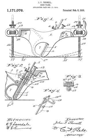
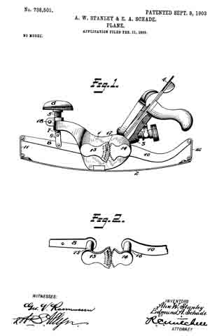
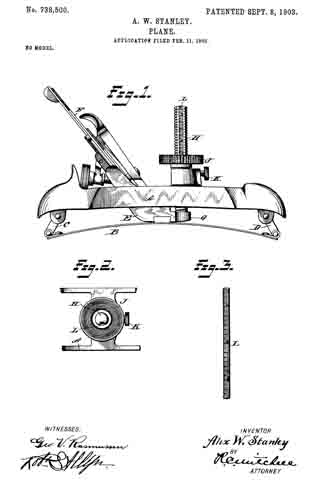
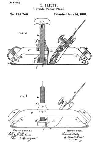
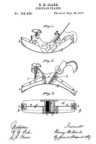
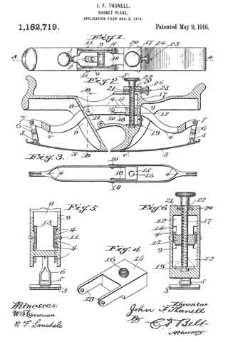
In the accompanying drawings forming part of this application :– Figure 1 is a top view of a rabbet plane embodying my invention. Fig. 2 is a sectional view taken on the plane indicated by the dotted line A–A Fig. 1, with the bit adjusting device removed. Fig. 3 is a detail plan view of the runner operating levers and follower block. Fig. 4 is a detail perspective view of the screw-locking device. Fig. 5 is an enlarged sectional view taken on the dotted line B–B Fig. 2. Fig. 6 is a similar view taken on the dotted line C–C Fig. 2.

The same reference characters denote the same parts throughout the several views of the drawings.

The means operated by the screw 1, for adjusting the bit 2, is covered by my application Ser. No. 872,608, allowed July 12, 1915, and therefore the same is not claimed in this application, and while the runners of this application are the same as those shown in said allowed application, the mechanism for operating the flexible runners 3, and the device for locking said mechanism to fix the runners in various positions constitute the subject of this application.

The runner operating mechanism comprises a pair of duplicate levers 4, pivotally connected at 5 with the movable end of the runners 3, by a forked hanger 6, pivoted at 7, to the outer end of the levers 4 where they are united in pairs. The levers 4 are branched laterally in pairs from their outer end and extend through the inclined throat wall 3 and adjacent to the side walls 9 of the throat. The pair of levers for one runner are pivoted to the pair of levers for the other runner by pivot pins 10, and the levers of one pair are pivoted at 11, to the throat walls 9, while the levers of the other pair are fulcrumed to and between the walls 9 and a vertical wall 12. One pair of the levers are operated through slots 13, in the wall 8, and the other pair of levers are operated through slots 14, in the wall 12. The device for operating the levers comprises a follower block 15 having a screw threaded aperture 16, for a screw 17, and a pair of arms 13 fulcrumed to the lever 4 by means of the lever pins 10. The screw 17 is anchored by means of a bracket 19 secured to and projecting inwardly from the wall 12, and said screw projects through a top wall 20 of the plane and is provided with a milled head for turning the screw in the anchor bracket, whereby the follower block 15 is moved vertically, and by such movement operates the levers 4 which carry the runners 3 to various curved positions as desired or as occasion may demand. The device for locking the screw and thereby fixing the levers and the runners in desired position for operating the plane, comprises a plate 21 slidably contained within the wall 20, and having an aperture 22 for the screw 17, and a screw stem 23 provided with a thumb nut 24 working against the outer face of the wall 20 for sliding the plate into and out of engagement with the screw. Obviously when the screw is locked the levers 4 and the runners are fixed in position for operating the plane.

It will be seen that the movement of the levers and runners is not only accomplished by operating the screw 17, but the screw and its locking device controls the levers and the runners so that the set position of the runners may be maintained during a planing operation. It will be further observed that the runner adjusting mechanism affords means for giving the runners minute curvatures, and that such curvature must be the same in both runners, under one and the same movement of the screw.

I do not wish to limit myself to any particular number of levers for operating the runners, to the size, material or shape of any of the parts of my invention, nor to the particular location of the pivot and fulcrum points of the runner operating levers, but reserve the right to make such changes and variations in the practical application of the invention as may come within the scope of the appended claims.

Having thus described my invention what I claim as new and desire to secure by Letters Patent is:–

1. In a plane, a pair of flexible runners having one end secured opposite the bit slot of the plane, a pair of fulcrumed levers pivotally connected with each runner, the levers of one runner being pivoted to the levers of the other runner, a vertically movable screw block having arms pivoted on the pivot of said levers, a vertical screw extending through the block for operating the levers, an anchor bracket attached to the outer side of the stock and holding the lower end of the screw, and a plate slidable at right angles to the screw for locking the screw.

2. The combination with flexible plane runners, runner levers pivoted together and to the walls of the plane stock, a follower screw block movable vertically between the levers of one pair and having arms pivoted to the connecting pivot of said levers, a vertically anchored screw working through the block for operating the levers, and a plate contained within the top of the stock and slidable in the path of movement of the screw for locking the screw.

3. In a device for operating flexible plane runners, two pairs of pivoted runner levers, pivots connecting the inner end of the levers, a follow screw block between the levers of one pair and having a pairof arms pivoted on said pivots, a vertically anchored screw working through the block for operating the levers, and a locking plate having a screw stem for sliding the plate into the path of movement of the screw.

In witness whereof I hereunto set my hand in the presence of two witnesses.

JOHN F. THUNELL.

Witnesses:
ISAAC P. THUNELL,
NEPHIN GLEDHILL.

_________________

Copies of this patent may be obtained for five cents each, by addressing the “Commissioner of Patents, Washington, D. C.”
_________________

No. 1,171,076 – Hand-Plane (John F. Thunell) (1916)

[paiddownloads id=”709″]1171076


UNITED STATES PATENT OFFICE.

_________________

JOHN F. THUNELL, OF SALT LAKE CITY, UTAH.

HAND-PLANE.

_________________

1,171,076. Specification of Letters Patent. Patented Feb. 8, 1916.
Application filed November 17, 1914. Serial No. 872,608.

_________________

To all whom it may concern:

Be it known that I, JOHN F. THUNELL, a citizen of the United States, residing at Salt Lake City, in the county of Salt Lake and State of Utah, have invented certain new and useful improvements in Hand-Planes, of which the following is a specification.

This invention relates to bit adjustments for hand planes, and the object of the invention is to provide novel and peculiar means for adjusting hand plane bits which shall be of simple construction, conveniently assembled, and accurately manipulated.

The object of the invention is to provide novel and peculiar means for adjusting and fixing the plane bit, and special means for hanging and adjusting the base or surface bearing plates of the plane.

A further object of the invention is to provide in the bit adjustment, convenient, simple, durable and effective means for giving the bit minute, accurate and positive adjustment independent of the base plate adjustment.

A still further object of the invention is to provide a pair of surface or runner plates, and a screw rod hinged to each plate, and a pair of adjusting and locking nuts for each rod, the adjusting nuts being held within the plane stock.

Other objects, advantages and improved results will be found in the practical application of the plane.

In the accompanying drawings forming part of this application: Figure 1 is a side elevation showing in dotted lines the various positions of the base plates. Fig. 2 is a sectional view of the bit device. Fig. 3 is a detail cross section on the dotted lines x–x, Fig. 2. Fig. 4 is a detail perspective view of the bit bracket.

The same reference characters denote the same parts throughout the several views of the drawings.

The plane stock or body 1, has a concavity 2 in its top in which set-screws 3 and 4 are operated in connection with a bit 5 and its keeper 6. The screw 3 works through a hinged carrier 1a, to connect the keeper therewith, and the thumb screw 4 works through the upper end of the keeper as usual. A transverse opening 7 is made through the stock under the ccncavity 2, and a bit slot 2a is made through the bottom wall of the opening 7. The under side of the stock is cut out at 8, for the purpose of reducing the weight of the plane, and for the purpose of housing the bit adjusting device. The bit adjusting device comprises a bracket the long plate 9 of which has a lug 8a working in the bit slots 9a covered by the plate 9, and the short plate 10 of the bracket is secured to the inclined wall 11 of the cut out portion 8 of the stock. The plate 10 forms a collar 10a in which a worm screw 12 is operated. Said screw having a stem extending through the top of the stock on an incline and parallel with the bit, and the stem is provided with a thumb head 13 for operating the screw. The plate 9 is provided with a follower projection 14 meshing with the screw 12, and the plate 9 has a forked end for the plate 10.

The pair of flexible runners 15, have their inner ends secured flush with the bit slot 2a, and the outer end of each plate is curved upwardly. A screw rod 16 is hinged or pivoted at 17 adjacent to the said curved end of each plate, and said rods extend through the ends of the stock 1. The ends of the stock are provided with transverse slots 18 and hold thumb nuts 19 for operating the rods 16, and set nuts 20 are provided for holding the rods in set position. One end of the stock is provided with a hand abutment 21 projecting above the nut 20 at this end of the stock, and thereby prevents the hand from interfering with the nut and rod.

It will be observed that the follower answers two purposes, it forms the connection between the bit and the bracket, and it also affords means for imparting to the bit the movement of the worm screw.

Having thus described my invention what I claim as new and desire to secure by Letters Patent is :–

In a bit plane, a plane throat the under wall of which has a slot lengthwise thereof, a plate of larger area than the slot and slidable on the under face of said wall opposite the slot, a lug on the upper face of the plate and projecting through the slot into engagement with the bit, a lug on the lower face of the plate, and a screw spaced apart from said wall equal to the thickness of the plate and engaging the plate and the lower lug to keep the upper lug in engagement with the bit for longitudinal adjustment by the screw.

In witness whereof I hereunto set my hand in the presence of two witnesses.

JOHN F. THUNELL.

Witnesses:
ISAAC P. THUNELL,
MATIE S. ASHTON.

_________________

Copies of this patent may be obtained for five cents each, by addressing the “Commissioner of Patents, Washington, D. C.”
_________________

No. 789,255 – Convertible Plane (Sidney C. Carpenter) (1905)

[paiddownloads id=”620″]789255


UNITED STATES PATENT OFFICE.

_________________

SIDNEY C. CARPENTER, OF WEST HARTFORD, CONNECTICUT.

CONVERTIBLE PLANE.

_________________

SPECIFICATION forming part of Letters Patent No. 789,255, dated May 9, 1905.
Application filed September 1, 1904. Serial No. 223,046.

_________________

To all whom it may concern:

Be it known that I, SIDNEY C. CARPENTER, a citizen of the United States, residing at West Hartford, in the county of Hartford and State of Connecticut, have invented certain new and useful Improvements in Convertible Planes; and I do declare the following to be a full, clear, and exact description of the invention, such as will enable others skilled in the art to which it appertains to make and use the same.

My invention relates to convertible planes of that character designed to be used for planing curved or flat surfaces; and the objects of same are to provide a plane with a spring bearing-surface which may be readily and quickly adjusted to the required degree to bear upon surfaces of more or less curvature and which may be readily converted into a plane of the ordinary or usual construction provided with a flat bearing-surface.

Another object is to provide a plane of this character which may be quickly and accurately adjusted for use under varying conditions and which will be provided with means for adjusting cutting-blades or bits relatively, accurately, and quickly.

These and other objects are attained by means of the construction illustrated in the accompanying drawings, in which —

Figure 1 is a side view of a plane constructed in accordance with my present invention and having the curved spring bearing-plate secured thereto. Fig. 2 is a perspective view of the spring bearing-plate detached from the plane. Fig. 3 is a perspective view of the fiat plane-surface which may be substituted for the spring when it is desired to convert the device into an ordinary plane. Fig. 4 is a vertical section on the line 1 1, Fig. 1. Fig. 5 is a longitudinal section on the line 2 2, Fig. 1.

Referring to the drawings for a more particular description of my invention, the numeral 1 designates the body portion of the plane, said body portion being oppositely inclined in front and rear, as shown at 2 3, and provided with suitable handles 4 5 and a cutter or bit 5a. A transverse slightly-curved surface 6 is provided at the central lower portion of the stock or body, and a lug 8, extending upward from the curved steel plate 9, is secured to the stock by a bolt 21, said plate forming the bottom or bearing surface of the plane. Near opposite ends of the plate 9 are lugs 10, projecting upward, said lugs being connected to links 11, pivoted at 12 and connected at their upper ends at 13 to longitudinal levers 14 and 15. Said levers 15 extend toward the middle of the frame upon opposite sides thereof and are connected by a pin 16, extending through the body or stock of the plane and through the front levers 14, a link 17 connecting said levers with a pivoted bolt 18, having fitted thereon a nut 19 for adjusting the levers 14 15 upon their pivots 20 to raise or lower the links 11, and thus adjust the spring-plate 9 to the required curvature for the work to be operated upon.

If it is desired to convert the plane into one of ordinary construction, the bolt 21 may be removed and the plate 22 substituted for the spring-plate in an obvious manner.

From the foregoing it will be obvious that my plane is of comparatively simple construction and may be readily converted from a circular to a flat-bottom plane. The curved steel plate may be readily adjusted to the required degree, depending upon the degree of curvature of the work to be performed.

Having thus described my invention, what I claim as new, and desire to secure by Letters Patent, is —

A plane comprising a stock having oppositely-inclined bottom faces, a spring face-plate secured to said stock between said inclined surfaces, said face-plate having upwardly-extending end lugs, links pivoted to said lugs, levers pivoted to said links and extending longitudinally to the center of the stock, a pin connecting the meeting ends of said levers, a link connected to said pin, a bolt connected to said link, and a nut for adjusting the bolt, the levers and the spring, substantially as described.

In testimony whereof I have hereunto set my hand in presence of two subscribing witnesses.

SIDNEY C. CARPENTER.

Witnesses:
JOSEPH P. KENNEDY,
JOHN D. WOOD.

No. 738,501 – Plane (Alix W. Stanley And Edmund A. Schade) (1903)

[paiddownloads id=”589″]738501


UNITED STATES PATENT OFFICE.

_________________

ALIX W. STANLEY AND EDMUND A. SCHADE, OF NEW BRITAIN, CONNECTICUT,
ASSIGNORS TO STANLEY RULE & LEVEL COMPANY, OF NEW BRITAIN,
CONNECTICUT, A CORPORATION OF CONNECTICUT.

PLANE.

_________________

SPECIFICATION forming part of Letters Patent No. 738,501, dated September 8, 1903.
Application filed February 11, 1903. Serial No. 142,845. (No model.)

_________________

To all whom it may concern:

Be it known that We, ALIX W. STANLEY and EDMUND A. SCHADE, citizens of the United States, residing at New Britain, in the county of Hartford, State of Connecticut, have invented certain new and useful Improvements in Planes, of which the following is a full, clear, and exact description.

This invention relates to planes, and particularly to improvements in the construction of that class of planes adapted to be used on curved surfaces, sometimes called “circular planes.” In planes of this character the base or sole is made flexible, so that it may be bent to any desired curve to cause the plane to fit onto a curved surface, either concave or convex. The sole portion of the plane is usually made of sheet metal, such as spring-steel. It is highly desirable in planes of this character that means be provided whereby the adjustment of the sole to the desired curve may be effected accurately and quickly. To that end, therefore, the main object of this invention is to provide simple and effective mechanism for attaining these results.

In the accompanying drawings, Figure 1 is a side elevation illustrative of a specific embodiment of my invention, the sole of the plane being curved to fit to a concave surface. Fig. 2 is a fragmentary perspective view of detached details of construction.

1 is the main body portion.

2 is the base or sole portion. The sole portion 2 is capable of being curved relatively to the main body portion 1. In the form shown the portion 1 is connected to the middle portion of the sole 2.

3 is the frog, carried by the frame 1 and in turn supporting the plane-iron 4. and the adjustments therefor. It is not necessary to explain in detail the adjustments for the plane-iron, because they are well known and constitute no part of this invention.

5 is a screw-threaded post mounted in a suitable screw-threaded bearing on the forward part of the body 1.

6 is a knob or handle carried by the post 5. When said post is rotated it will move up and down relatively to the body 1.

7 is a telescopic extension of the post 5. The connection between the post 5 and its extension 7 is screw-threaded. The screw-threads on the post which take into the frame 1 are right-hand threads, while the screw-threads on the extension 7 which take into the post are left-hand threads, or vice versa. The post extension 7 is connected to a lever 8 by means of a link 9. The lever 8 is pivotally mounted in the body 1. The link 9 prevents the extension 7 from rotating. The particular screw-threaded adjustment of the post 5 relatively to the frame 1 and the extension 7 relatively to the post 5 produces double the movement of the lower end of the extension 7 that would be produced were the link 7 merely projected into the post 5 without being oppositely screw-threaded. The lever 8 is connected with one end of the sole 2 by means of the link 11. 10 is another lever pivotally mounted in the body 1 and connected to the opposite end of the sole 2 by the link. 12.

15 is a pivot for the lever 8.

16 is a pivot for the lever 10. 13 14 are segmental gears fixed on the pivots 15 16, respectively, so that the movement of one of said levers will be transmitted to the other — for example, the movement of the lever 8 by the aforesaid means will produce a corresponding movement in the lever 10. Hence as the lever 8 is moved upwardly the sole 2 will be curved upwardly. If the lever 8 is moved downwardly, the sole 2 will be curved downwardly, and the position of the levers 8 and 10 and the degree and direction of curvature of the sole 2 are deterininable solely by the handle 6. By means of a suitable indicating device it may be ascertained whether the sole is flat or curved and if curved what degree of curvature exists in the sole. In the particular form shown the indicating device comprises a pointer 17, carried by one of the parts — for example, the body 1 — in such a position as to project into the path of movement of certain graduations carried by another part — for example, the segmental gear 13. Referring to Fig. 1, it will be seen that the pointer 17 projects into a curved slot in the segmental gear 13, adjacent to which curved slot there are certain graduations from zero upward and downward. These graduations indicate degrees of curvature in the sole. When the zero-mark on the graduated scale lies opposite the pointer or line of reading, it indicates that there is no curve in the sole. If any one of the graduations above the zero-mark is brought into line with the pointer, it indicates to the user that the sole is curved upwardly to a certain definite degree. The reverse is true of the graduations below the zero-mark. It might be said that the segmental gear 13 constitutes a movable pointer, which enables the user to accurately set the plane so that the sole will be curved to any desired degree to fit to any particular curved surface, and this adjustment may be accurately and quickly effected without any preliminary trials, such as fitting the plane to the particular curved surface upon which it is desired to operate. When the plane has been set as desired, a set-screw 18 may be operated to clamp the adjusting screw or post 5 and prevent accidental displacement. The set-screw 18 may operate to clamp a split collar on the frame 1, through which the adjusting-post 5 passes.

The subject-matter disclosed and claimed herein is a specific embodiment of the invention broadly claimed in Alix W. Stanley’s application for United States Letters Patent, Serial No. 142,844, filed February 14, 1903.

What is claimed is —

1. A plane for cutting curved surfaces comprising a body portion, a sole portion secured thereto, adjusting-arms pivotally secured to the body portion and connected to the sole portion, segments of gears carried by the pivotal supports, an index or scale carried by one of said segments, and a stationary indicator or pointer carried by the body portion of the plane coacting with the scale or index whereby the degree of curvature of the sole portion may be indicated.

2. A plane comprising a body portion, a flexible sole portion secured thereto, a pair of arms pivoted in said body portion and connected to the ends of the sole portion, an index or scale carried by one of said arms, and a relatively stationary indicating member carried by the body portion of the plane and coacting with the scale or index for indicating the degree of curvature.

3. A plane for cutting curved surfaces comprising a body portion, a sole portion secured thereto, a pair of arms pivoted to the body portion and connected to the sole portion, gear-segments mounted to operate with said arms, one of said segments being slotted and having a scale or index adjacent the slotted portion, and an indicating member carried by the body portion of the plane cooperating with the scale or index for the purpose specified.

Signed at New Britain, Connecticut, this 7th day of February, 1903.

ALIX W. STANLEY.
EDMUND A. SCHADE.

Witnesses:
ROBERT N. PECK,
WILLIAM J. WORAM.

No. 738,500 – Plane (Alix W. Stanley) (1903)

[paiddownloads id=”588″]738500


UNITED STATES PATENT OFFICE.

_________________

ALIX W. STANLEY, OF NEW BRITAIN, CONNECTICUT, ASSIGNOR TO
STANLEY RULE & LEVEL COMPANY, OF NEW BRITAIN,
CONNECTICUT, A CORPORATION OF CONNECTICUT.

PLANE.

_________________

SPECIFICATION forming part of Letters Patent No. 738,500, dated September 8, 1903.
Application filed February 11, 1903. Serial No. 142,844. (No model.)

_________________

To all whom it may concern:

Be it known that I, ALIX W. STANLEY, a citizen of the United States, residing at New Britain, in the county of Hartford, State of Connecticut, have invented certain new and useful Improvements in Planes, of which the following is a full, clear, and exact description.

My invention relates to planes, and particularly to that class of planes adapted to be used on curved surfaces, sometimes termed “circular planes.” In planes of this character the base or sole portion is so arranged that it maybe made to assume different curvatures to cause the plane to properly fit to surfaces of different degrees of curvature upon which it is desired to operate the tool. These curvatures may be either concaved or convex. In the particular form shown the sole or base is made of flexible material, such as sheet metal or spring-steel. When adjusting the sole to the desired curvature, it is most desirable that said adjustment may be effected accurately and quickly.

To that end, therefore, the object of my invention is to provide simple, effective, and durable means whereby the plane may be so adjusted that exactly the proper curvature will be given to the sole without requiring the user to make any preliminary trials to ascertain whether the plane fits the curved surface on which it is to be used.

Figure 1 is a side elevation illustrative of one particular embodiment of my invention, the sole of the plane being curved to operate on a convex surface. Fig. 2 is a fragmentary plan view of the setting and reading mechanism. Fig. 3 is a perspective view of the scale.

A is a frame or main body, perfectly rigid.

B is a base or sole, which may be made of any flexible material, preferably spring sheet-steel.

C D are links located at the ends of the sole and in the particular form shown connected with the ends of the frame A.

E is a frog connected with the sole B and supporting the plane-iron F and the adjustments therefor, which latter need not be explained, because they constitute no part of this invention.

H is a post connected with the frog E. In the particular form shown the post H passes up through a portion of the body A, and on the post is mounted a screw-threaded adjusting device J in the form of a thumb-nut. This thumb-nut is rotatable in the body A, but is held against longitudinal movement. Hence when this thumb-nut is rotated the post H is moved up or down to produce a curvature of the sole B.

K is a screw by the rotation of which the thumb-nut J may set at any desired position to lock the adjusted parts against accidental displacement. In the form shown one side of the post H is flattened and upon said flattened surface is a graduated scale L. The graduations may, however, be formed upon the post itself. This scale runs from zero upward and downward, the graduations being proper to indicate to the user the exact curvature of the sole. These graduations are read on the line of the upper surface of the thumb-nut J, since that member is relatively stationary and its upper surface constitutes a convenient indicating-line. The zero-mark when registering with the indicating line means to the user that the sole is flat and not curved either upwardly or downwardly. If the thumb-nut J is so turned as to raise the post H, the graduation thereon adjacent the indicating-line indicates to the user the curvature of the sole. In Fig. 1 the zero-mark will be seen to be above the indicating-line. Hence the sole is curved upwardly, so that the plane may be used on a convex surface. Were the post depressed, so that some graduation above the zero-mark should lie adjacent to the indicating-line, it would show to the user that the sole is curved downwardly. The particular graduation would indicate to him the exact curvature of the sole.

The construction as a whole is simple and reliable and facilitates the accurate and quick adjustment of the sole to any definite curvature without the necessity of making any preliminary trials.

It is apparent that the plane herein specifically shown and described is capable of modification without departing from the spirit or scope of the invention.

Another specific embodiment of this broad invention is shown in a companion application, Serial No. 142,845, filed February 14, 1903.

What is claimed is —

1. A plane for operating on curved surfaces comprising a relatively stationary frame or body portion, a flexible sole portion secured thereto, an adjusting post or screw coacting with the flexible sole portion, and the relatively stationary body portion, a scale or index carried by the adjusting post or screw and a relatively stationary indicating member coacting with the post for the purpose of determining the change of curvature of the sole portion as indicated by the scale, said indicating member having a rotative movement relatively to said body.

2. A tool for planing curved surfaces comprising a relatively stationary body portion, a flexible sole portion carried thereby and movable relatively to the body portion, an adjustable scale-carrying member movable with the sole portion, and a relatively stationary indicating member carried by the body portion cooperating with the scale portion whereby the relative positions of the body and sole portions of the plane may be measured, said scale having graduations running upward and downward from zero.

3. A plane for curved surfaces comprising a body portion, a relatively movable and flexible sole portion pivotally mounted with respect thereto, an adjusting-screw operating in the body portion and cooperating with the sole portion, a scale or index carried by said screw, an adjusting-nut operating on said screw and in conjunction with the body portion, one edge of the adjusting-nut being adapted to act as a pointer or indicating member in conjunction with the scale for determining the relative positions of the body and sole portions.

Signed at New Britain, Connecticut, this 7th day of February, 1903.

ALIX W. STANLEY.

Witnesses:
ROBERT N. PECK,
WILLIAM J. WORAM.

No. 300,399 – Plane (Solon R. Rust And Arthur E. Rust) (1884)

[paiddownloads id=”368″]300399


UNITED STATES PATENT OFFICE.

_________________

SOLON R. RUST AND ARTHUR E. RUST, OF PINE MEADOW, CONNECTICUT.

PLANE.

_________________

SPECIFICATION forming part of Letters Patent No. 300,399, dated June 17, 1884.
Application filed March 26, 1884. (No model.)

_________________

To all whom it may concern:

Be it known that we, SOLON R. RUST and ARTUR E. RUST, of Pine Meadow, in the county of Litchfield and State of Connecticut, have invented certain new and useful Improvements in Planes; and we do hereby declare that the following is a full, clear, and exact description thereof, whereby a person skilled in the art can make and use the same, reference being had to the accompainying drawings, and to the letters of reference maarked thereon.

Like letters in the figures indicate the same parts.

Figure 1 is a view in longitudinal central section of my improved plane. Fig. 2 is a top view of the same. Fig. 3 is a side view of the same. Fig. 4 is a view in cross-section of the adjustable yoke on plane denoted by line x x of Fig. 3. Fig. 5 is a detail perspective view of the carriage which supports the plane-iron.

Our invention relates to the class of planes having a flexible face and means for adjusting the plane-face for working on a convex or concave surface.

It also embraces certain features of construction applicable broadly to planes.

lt consists in the combination of a plane-body with a flexible face and means for adjusting the face, and in the combination of devices for holding and adjustiiig the cutting-iron of the plane-body, as more particularly hereinafter described.

In the accompanying drawings, the letter a denotes the plane~body as a whole,made of any suitable material — as iron — having a bed, a’, through which the plane-iron projects, vertical sides a5, which support the face and the blade-adjusting devices, respectively. The flexible face b is fast to the plane-base, and the forked arms c and d are pivoted to the plane-body, as by means of pivots c’ d’, and to the outer ends of the face, as by means of the links c and f. Each of these levers has a short arm, c2 d2, pivotally connected to each other by rods g, The yoke h is pivoted at its lower end to each arm of the lever c near the pivots c’, and bears between the upper and lower crossbars, h1 h2 , an adjusting-screw, i, which is arranged about centrally of the plane-body in a threaded socket in the cross-piece a2, fast to the plane-body in front of the plane-iron. Any vertical movement of the yoke imparted to it by the adjusting-screw i is transmitted to the lever c, and by means of connecting-rods g to the lever d, and from these levers c d to the opposite extremities of the flexible plane-face. This adjustment of the plane-face may be made to a convex surface, as denoted by dotted lines in Fig. 1, or to a concave with equal ease.

The adjustable carriage k is supported in the plane-body by means of the longitudinal and central bearings, l l’, the former resting upon the cross-bar a2, fast to the plane-body, and the latter in a tubular socket, a1, in the plane-body. The carriage k has the downward-projecting lugs k1 k2, against the inner faces of which bear the opposite ends of an adjusting-screw, m, which moves in a threaded socket in the cross-bar a3, fast to the plane-body. This carriage also has the arms n, with the inward-projecting extremities n’, so arranged as to grasp the upper surface of the clamp-iron o, placed over the iron p upon the carriage, when the parts are in position in the plane-body. The lower end of the clamp-iron bears upon the plane-iron just back of the cutting-edge, and its upper end bears the clamp-screw o’, moving in a threaded socket near the upper end of the clamp, and with its point bears upon the upper surface of the plane-iron. The central bearings of the carriage permit of a lateral motion of the carriage and the supported plane-iron, by means of which the plane-iron may be adjusted to a perfect bearing in the socket in the body. The peculiar method of holding the adjusting-screw between the lugs projecting from the carriage prevents backlash or lost motion of the parts and permits a more careful adjustment.

The plane-body, yoke, and the carriage of our improved plane are made, preferably, of metal — as iron — cast to shape, with threaded sockets and bearings for the adjusting-screws and bearings for the carriage formed in subsequent operations.

The main advantage of our improved device is the low cost of its manufacture and simplicity of the operating parts, which perform the functions attainable in like devices of the prior art only at considerable expense.

The peculiar method of holding the clamping-screw between the lugs on the lower part of the carriage relieves the maker of the tool from exercising any great care to get the bearings for the carriage and the axis for the adjusting-screw parallel, as the opposite ends of the adjusting-screw may have lateral play between the lugs and not render the device inoperative.

The plane may be quickly changed from a single-iron plane to a double-iron plane by sliding back the clamp, and the plane-iron adjusted for cutting without changing the clamp, but by simply turning the adjusting-screw m.

We claim as our invention —

1. In combination, in a flexible face-plane, a plane-body, a, a flexible face, b, levers c d, pivotally connected to the plane-body, to each other by connecting-rod g, and to the flexible face-plate, with means for changing the position of said levers and of the flexible face, all substantially as described.

2. The combination of a plane-body, flexible face, pivoted levers connecting the said face and the body, a yoke, h, pivotally connected to the said levers, and an adjusting-screw, i, having bearings in the yoke and in the plane-body, all substantially as described, and for the purpose set forth.

3. The combination of a plane-body, a, a carriage, k, with the central bearings, l l’, fitted to suitable bearings in the plane-body, and with lugs k1 k2, bearing upon opposite extremities of an adjusting-screw, m, attached to the body, all substantially as described.

4. In a plane, the combination of a plane-body, a, a carriage, k, with central bearings, l l’, projecting lugs k1 k2, and projections w’, an adjusting-screw, m, with its opposite ends bearing on the inner faces of the lugs, plane-iron p, and clamp-iron o, with clamp-screw o’, all substantially as described.

5. In a plane, the combination of a plane-body and a carriage having lugs bearing upon opposite extremities of an adjusting-screw, m, movable in a socket in a plane-body, all substantially as described, and for the purpose set forth.

6. In combination, a plane-body, a, having bed a’, cross-bars a2 a3, and socket a4, the forked levers c d, pivoted to the body, connecting-rods g, yoke h, pivoted to the levers, and adjusting-screw i, with plane-iron p and means for holding the same in the body, all substantially as described, and for the purpose set forth.

SOLON R. RUST.
ARTHUR E. RUST.

Witnesses:
JOSEPH W. DREYRUON,
O. S. THOMPSON.

No. 242,740 – Flexible-Faced Plane (Leonard Bailey) (1881)

[paiddownloads id=”313″]242740


UNITED STATES PATENT OFFICE.

_________________

LEONARD BAILEY, OF HARTFORD, CONNECTICUT.

FLEXIBLE-FACED PLANE.

_________________

SPECIFICATION forming part of Letters Patent No. 242,740, dated June 14, 1881.
Application filed November 13, 1880. (No model.)

_________________

To all whom it may concern:

Beit known that I, LEONARD BAILEY, of Hartford, in the State of Connecticut, have invented certain Improvements in Flexible-Faced Planes, of which the following is a specification.

My invention relates to that class of planes in which the face is made flexible, so that by means of a screw or equivalent device it may be adapted to concave or convex surfaces of different degrees of curvature; and it consists in improvements upon these planes, as now constructed, in four particulars.

In the drawings, I have shown in Figure 1 a side elevation of a plane embodying my improvements, and in Fig. 2 a longitudinal section of the same.

The first part of my invention relates to the screw for regulating the degree of curvature of the face, and more especially to the method of attaching it to the stock, so that it shall be capable of adjustment in case of wear by use.

In the Letters Patent to Charles H. Sawyer dated April 16, 1867, numbered 63,948, is described a screw passing through the center of the handle or stock, and attached to a piece which is rigidly fastened to the upper surface of the face, by means of which screw the curvature of the face is regulated. It is a matter of great importance in tools of this character that the adjusting-screw should be firmly fixed at the base and yet be permitted to turn freely. When, however, the base of the screw attached to the face, or to a piece of metal affixed to the face, becomes worn, which will happen after the tool has been used for a while, it ceases to be firmly held and becomes loose, and consequently more or less unfitted for use, or altogether useless. It is very desirable, therefore, to provide such means for adjusting the screw, in case of wear, as will overcome this difticulty. In the Sawyer patent referred to no means are provided to overcome the difficulty. I accomplish this very important object by the first part of my invention and in the following way: In the forward part of the stock a is a place for the reception of the base b’ of the screw b, which is somewhat larger in diameter than the main part of the screw. Upon the screw, below the piece c, is placed the nut d, which is of the same diameter as the base b’, and adapted to slide up and down the main part of the screw b. This nut d is fitted with screw-threads, which fit into screw-threads inside the place provided in the stock a for the reception of the base b’ of the screw. Around the periphery of this nut d are countersunk places d’ d’. When the base b’ of the screw b is placed inside of the place in the stock provided for its reception the nut d is to be screwed down and into this place. By this means the screw b is held firmly, and yet may be readily turned. When the screw becomes loose by reason of wear occasioned by use it may be readily tightened by screwing down the nut d sufficiently to accomplish this object. This may be done by means of the countersunk places d’ d’, in which any suitable tool may be inserted to turn the nut d. The screw b passes through the piece c, within which are screw-threads, with which the screw b engages. This piece is fastened to the frame e. Above this piece is the nut f, which travels along the screw b, the office of which is to assist in holding the screw b at any desired point. This is accomplished by screwing the nut f down to the piece c.

The second part of my invention relates to the frame to which the flexible face is attached, (marked e in the drawings,) and consists in making it of two pieces instead of one, as is now the case. This change will be found to be an important one in respect of ease and economy in manufacture, for instead of casting the entire frame in one piece, as is necessary in case of planes as they are now made, the two parts may be struck out of sheet metal and bent into the proper shape. These two pieces are united by the pins h h, with the rods i i connecting the frame e with the flexible face j, the rods turning upon the pins k k, by which they are attached to the face. Just above the rods i i are placed the handles m m, held in place by the screws n n.

The third part of my invention consists of a device for detaching the face from the stock when desired without injury to the former; and consists of the plate o, to which the face is permanently riveted, and which is connected with the stock a by means of two screws, o’ o’, passing through the stock and into but not through the plate o. Through this plate o and the face pass the cutting-irons p p. By the use of this device the face is rigidly attached to the frame, but can be easily detached by removing the screws o’ o’ without in any way injuring the face or affecting its smoothness, which it is of the utmost importance to preserve, and which would be impaired if the face were fastened directly to the frame or stock by means of screws passing through the face, as is now generally the case. This part of my invention is adapted to all classes of planes.

I am aware that in the Letters Patent to Samuel D. Sargent, dated June 17, 1879, and numbered 216,577, a transverse recess adjacent to the throat and attached to the stock, and an independent throat-piece fitted to said recess and attached to the face, are described and shown; but my invention, just described, differs from that, inasmuch as the plate o is not a throat-piece, and has no other office or use than to attach the face to the stock in such manner as that it may be readily detached, and its mode of attachment to the stock is entirely different.

The fourth part of my invention consists in providing a head, q, in place of a crank, such as is used by Sawyer, as described by him in his said Letters Patent, for the purpose of turning the screw b, and an improved method of attaching this head to the screw, which is done by inserting the head in the slot r in the upper end of the screw b and holding the head in place by the screw s. By this means the screw b may be more readily turned, and also the head may be more easily attached or detached, as desired.

What I claim, and desire to secure by Letters Patent, is —

1. The combination, with flexible face j, piece c, stock a, and the frame to which they are attached, of screw b, having flange b’, and nut or collar d, which engages with a recessed part of said stock and operates to hold said stock and screw together, substantially as set forth.

2. A plane-frame consisting of two corresponding sheet-metal side plates, which may be stamped or struck up by the same die, said plates being fastened at their ends by cross pins or rods, substantially as set forth.

LEONARD BAILEY.

Witnesses:
HENRY E. TAINTOR,
EDWARD B. BENNETT.

No. 216,577 – Improvement In Flexible-Faced Plane-Stocks (Samuel D. Sargent) (1879)

[paiddownloads id=”303″]216577


UNITED STATES PATENT OFFICE.

_________________

SAMUEL D. SARGENT, OF NEW BRITAIN, CONNECTICUT, ASSIGNOR TO STANLEY RULE AND LEVEL COMPANY, OF SAME PLACE.

IMPROVEMENT IN FLEXIBLE-FACED PLANE-STOCKS.

_________________

Specification forming part of Letters Patent No. 216,577, dated June 17, 1879; application filed April 16, 1879.

_________________

To all whom it may concern:

Be it known that I, SAMUEL D. SARGENT, of New Britain, in the county of Hartford and State of Connecticut, have invented certain new and useful Improvements in Flexible Faced Plane-Stocks, of which the following is a specification.

My invention consists of the combination, in a flexible-faced plane-stock, of the body of the stock, having a transverse recess adjacent to the throat, with an independent throat-piece fitted to said recess and having the flexible face attached, as hereinafter described; also, in the throat-piece, of malleable metal, independent or otherwise, and provided with a series of lugs rigidly formed in one and the same piece with the throat-piece, in combination with the flexible face-plate having a series of holes through which said lugs pass, as hereinafter described.

In the accompanying drawings, Figure 1 is a side elevation of a flexible-faced plane-stock which embodies my invention. Fig. 2 is alongitudinal section of the same through one side of the stock. Fig. 3 is a detached portion of the flexible-faced plate and attached throat-piece of the same. Fig. 4 is a detached under-side view of said throat-piece, and Fig. 5 is an enlarged sectional view on line x x of Fig. 3.

The flexible-faced stock, the mechanism for adjusting said face-plate, and the mechanism for adjusting the plane-iron are, with the exception of the parts hereinafter described, substantially the same as shown in the two patents to H. M. Clark, September 25, 1877; but they may be of any other style or kind.

The body of the stock A, I make of iron and with a dovetailed groove transversely across the bottom at the point where the throat a is designed to be located.

A dovetailed throat-piece, B, is fitted snugly into said groove, as shown in Figs. 1 and 2. This throat-piece has the ordinary throat a formed in it, through which throat the cutting-bit or plane-iron extends.

The flexible face-plate C is firmly secured to said throat-piece before it is inserted in the stock.

Heretofore, so far as I know, the flexible face-plates of circular plane-stocks have been secured directly and permanently to the stock, and generally by screws the heads of which were ground or polished off so as to take out the slot therein. A face-plate so secured could not be removed for repairs by an ordinary carpenter, and in any event could only be removed with more or less difficulty.

I intend to have the stocks and throat-pieces made by machinery and all alike, so that in case it is desired to remove the flexible face-plate and replace it with a new one it is only necessary to disconnect the ends of the face-plate and drive out the throat-piece.

A new face-plate can be ordered from the factory and inserted in its place, all of which can be done by any ordinary carpenter or mechanic, and without returning the plane-stock to the factory.

Thus it will be seen that the throat-piece and its attached face-plate are both attachable and detachable from the stock, whereby I call the throat-piece an independent one.

So far as the above feature of my invention goes the face-plate may be secured to the independent throat-piece by screws, rivets, or in other ordinary manner; but I prefer the method hereinafter described, and which constitutes the second feature of my invention.

I make the throat-piece of some kind of malleable metal, (good malleable iron will answer,)
and with a series of lugs, b, upon its under side. A mill is then run over the surface of the throat-piece both lengthwise and crosswise, to mill the entire surface, except that occupied by the lugs, leaving them square, as shown in Fig. 4.

A series of holes of corresponding shape and location are punched in the face-plate, which holes are conntersunk on the face side of the plate by a proper revolving tool. The lugs of the throat-piece are then driven into the holes in the plate, their ends upset or riveted, and then polished off, when the plate is ready for use.

The under face of the throat-piece outside of the lugs may be slightly rounded, and said piece may be made so thick that the face-plate will project slightly below the other parts of the stock, so that a good convex curve may be given to the face of said plate.

A few of the advantages of the solid lugs on the throat-piece are as follows, viz: Being short and solid, there is only the thickness of the plate for them to stretch, give, or work in, whereby they form a much firmer fastening than screws or rivets, which are necessarily longer, and the lugs may be set nearer to the throat a, especially with reference to the beveled side of the throat, thereby allowing the greatest possible freedom in bending the face-plate of the stock, while at the same time it is secured firmly.

I have herein described this second feature of my invention as embodied in an independent throat-piece; but if desired the same rigid lugs might be formed contiguous to the throat in the stock, the stock and throat-piece being made of a single piece of malleable iron, in which case the throat-piece would not be an independent one, but all the advantage of a firm fastening, by reason of short lugs and of fastening the face-plate near the edge of the throat, would be embodied in such a stock.

I claim as my invention —

1. In a flexible-faced plane-stock, the body of the stock, having a transverse recess adjacent to the throat, in combination with an independent throat-piece itted to said recess and having the flexible face attached, substantially as described, and for the purpose specified.

2. In a flexible-faced plane-stock, the throat-piece, of malleable metal, independent or otherwise, and provided with a series of lugs rigidly formed in one and the same piece with the throat-piece, in combination with the flexible face-plate having a series of holes through which said lugs pass, substantially as described, and fbr the purpose specified.

SAMUEL D. SARGENT.

Witnesses:
JAMES SHEPARD,
WILL. B. THOMSON.

No. 195,480 – Improvement In Circular Planes (Henry M. Clark) (1877)

[paiddownloads id=”282″]195480


UNITED STATES PATENT OFFICE.

_________________

HENRY M. CLARK, OF NEW BRITAIN, CONNECTICUT, ASSIGNOR TO THE STANLEY RULE AND LEVEL COMPANY, OF SAME PLACE.

IMPROVEMENT IN CIRCULAR PLANES.

_________________

Specification forming part of Letters Patent No. 195,480, dated September 25, 1877 application filed August 6, 1877.

_________________

To all whom it may concern:

Be it known that I, HENRY M. CLARK, of New Britain, in the county of Hartford and State of Connecticut, have invented certain new and useful Improvements in Circular Planes, of which the following is a specification:

My invention consists of a connecting mechanism for the two ends of the flexible bottom of a circular plane, so that they necessarily move together, in combining therewith a single operating device, in the peculiar construction of parts, and in their combination, as hereinafter described.

In the accompanying drawings, Figure 1 is a side elevation of a circular plane, which embodies my invention. Fig. 2 is a vertical section of the same on line y y of Fig. 3, and Fig. 3 is a horizontal section of the same on line x x of Fig. 2.

In Fig. 1 the flexible bottom A is set in a convex position for dressing a concave surface, and in Figs. 2 and 3 it is set in a concave position for dressing a convex surface.

Circular planes having a flexible bottom and mechanism for holding the same when set in various circles are old; but, so far as I know, the two ends of the flexible bottom have never before been so connected as to necessitate their simultaneous movement. These prior planes had no mechanism for moving the ends of the flexible bottom, but only mechanism for holding the ends in place when moved by hand; and these holding mechanisms were entirely independent of each other, so that unless great care was taken in setting the bottom, one end would be bent to conform to one sized circle and the other end to conform to a circle of a different size.

The object of my invention is to adjust the flexible bottom more conveniently than heretofore, and to always adjust both ends to the same circle.

The flexible bottom A is secured to the stock B by screws taking into the stock at each side of the throat, in the usual manner of securing the same in circular planes.

At one side of the stock B short shafts a a are secured in proper bearings, so as to partially rotate therein. On the inner ends of said shafts a a, and in the middle of the stock B, rocking levers C C are rigidly secured, so as to rotate with said shafts. The outer ends of the rocking levers C C are connected to the ends of the flexible bottom A by means of the links b b.

On the outer ends of the shafts a a, rigidly secured, are segment-gears c c, which mesh into each other and necessitate the movement of one shaft with its fellow.

Inasmuch as the rear end of the flexible bottom is longer than its front end, and describes a larger circle in bending, the segment-gear on the front or short end is made larger than the segment-gear on the long end, in order to cause the latter to move enough faster than the former to compensate for the difference in the size of the circle described by the two ends of the flexible bottom.

In the front end of the stock B there is a rocking block or nut, d, which receives the adjusting-screw e, surmounted by a suitable knob or handle, D. The screw e is also provided with an internal thread, running in the opposite direction from that of its external thread, which internal thread receives the adjusting-screw e’, the lower end of which is connected by a pin or other jointed connection to one of the levers.

By turning the adjusting-screw e e’, the lever C, to which it is connected, is either depressed or lowered, according to which way the screw is turned, thereby partially rotating the shaft a. The segment-gear on the outer end of the shaft, meshing into a like gear on its fellow shaft, carries the opposite lever with the one connected to the screw, and the ends of the flexible bottom being connected by the links to said levers, as shown, must necessarily move together; and if the size of the segment-gears is properly arranged in relation to the circles described by both ends of the flexible bottom, said ends will both of them always be bent to conform to the same circle under all the various adjustments which they undergo.

The double screw e e’ is merely for the purpose of increasing the motion of the lever, and may, if desired, be omitted, and a single screw substituted therefor.

Other means might be employed for moving the levers or securing them in place without changing the portion of the invention which relates to moving both ends of the flexible bottom together.

If desired, the segment-gears might be separated a little and a worm placed between them, so as to engage the teeth thereof, whereby turning the worm will simultaneously move both segment-gears, levers, &c., in either of which modifications a single handle only has to be manipulated to operate both ends of the flexible bottom.

I claim —

1. In a circular plane, the combination of the flexible bottom A and mechanism, substantially as described, connecting its two ends, for necessitating their simultaneous movement, substantially as described.

2. In a circular plane, the combination of the flexible bottom A, mechanism, substantially as described, connecting its two ends and necessitating their simultaneous movement, and a single adjusting or operating handle, substantially as described, and for the purpose specfiied.

3. In a circular plane, the combination of the stock B, flexible bottom A, link b, rocking lever C, and adjusting-screw e, substantially as described, and for the purpose specified.

4. In a circular plane, the combination of the flexible bottom A, links b b, levers C C, shafts a a, and sement-gears c c, substantiallly as described, and for the purpose specified.

HENRY M. CLARK.

Witnesses:
T. A. CONKLIN,
JAMES SHEPARD.

No. 166,239 – Improvement In Bench-Planes (David F. Williams) (1875)

[paiddownloads id=”250″]166239


UNITED STATES PATENT OFFICE.

_________________

DAVID F. WILLIAMS, OF WOONSOCKET, RHODE ISLAND, ASSIGNOR TO BAILEY TOOL COMPANY, OF SAME PLACE.

IMPROVEMENT IN BENCH-PLANES.

_________________

Specification forming part of Letters Patent No. 166,239, dated August 3, 1875; application filed May 24, 1875.

_________________

To all whom it may concern:

Be it known that I, DAVID F. WILLIAMS, of Woonsocket, Providence Plantations, and in the State of Rhode Island, have invented a new and useful Improvement in Bench-Planes; and I do hereby declare that the following is a full, clear, and exact description thereof, reference being had to the accompanying drawings making a part of this specification.

This invention relates to a bench-plane having a flexible steel face to allow of its being adjusted to operate upon any given circle or arc of a circle in either a concave or convex form; and it consists in certain improvements in the mode of fixing or holding the face after it has been bent to the desired curve, substantially as hereinafter more fully set forth, the object being to simplify the construction of the plane, and at the same time to secure a firmer adjustinent of the flexible face.

Figure 1 in the drawing shows the plane adjusted to operate upon a plane surface. Fig. 2 shows it adjusted to operate upon a concave surface, the dotted lines also indicating the position of the movable parts when the face is adjusted to operate upon a plane and on a convex surface. Fig. 3 is a front view, showing the opening in the stock and the slotted arm attached to the face-plate, which slides therein.

A in the drawings represents a metallic plane-stock, cast in the usual form for this class of planes. B is the flexible face of steel, made thinnest at its ends, and tapering from the center of its length, in order that when bent it may form a perfect curve. It is attached to the stock by means of screws on each side of the month of the plane. The ends of the plane-stock are split, as shown at a, Fig. 3, forming jaws E E, and, provided with set-screws D D, form clamps for the slotted arms C C’, which are attached, respectively, to the ends of the flexible shoe B. These screws pass through one side of the divided end of the plane-stock, and through the slot in said arms, and are screwed into threads formed in the other side or jaw of the clamp or stock, and, being provided with shoulders d, operate to tightly clamp the jaws. The arms C C’ are attached to the flexible shoe by being hinged at b to a piece, c, which is riveted to the shoe.

As the screws D are loosened, and the shoe B is bent in either direction the arms C C’ slide on the screws D in their slots, and permit the adjustment of the shoe to any desired curve.

The arm C’ is bent to prevent contact with the upper part of the plane-iron when the shoe is bent to a convex form.

What is claimed as the invention is —

1. A bench plane having a flexible face, in which the stock is split at either end to form a clamp, substantially as described.

2. The combination of the flexible shoe B, slotted arms C C’ hinged thereto, clamping-jaws E, and set-screws D, substantially as described.

D. F. WILLIAMS.

Witnesses:
WM. H. BAILEY,
J. E. BLOOD.

No. 113,003 – Improvement In Plane-Stocks (Leonard Bailey) (1871)

[paiddownloads id=”183″]113003


UNITED STATES PATENT OFFICE.

_________________

LEONARD BAILEY, OF NEW BRITAIN, CONNECTICUT.

IMPROVEMENT IN PLANE-STOCKS.

_________________

Specification forming part of Letters Patent No. 113,003, dated March 28, 1871.

_________________

I, LEONARD BAILEY, of New Britain, in the county of Hartford and State of Connecticut, have invented certain Improvements in Flexible-Faced Plane-Stocks, of which the following is a specification:

My invention consists in the combination of the parts, as hereinafter described.

The accompanying drawing shows a side elevation, partly in section, of a plane-stock of my invention.

A designates the stock proper, which I prefer to make of cast metal; but it may be made of any suitable material. B designates the flexible face-plate, which is made of spring-steel, and secured to the under side of the stock A, near the center of its length, by screws or rivets, in the ordinary manner.

At each end of the face-plate B is secured an arm, a a’, connected thereto by means of a suitable hinge, b b’. The arms a a’ pass through the rocking shafts c c’, which shafts are pivoted in each end of the stock A, in such manner as to easily rock or partially rotate.

By means of the set-screw d (shown at the left in the drawing) the arm a may be secured firmly in the rocking shaft c; or, if desired, the arm a’ may be threaded and held in place by a nut, d’, upon each side of the rocking shaft, as shown at the right in the drawing.

The peculiar mechanism employed to secure or fasten the arms a a’ in the rock-shafts c is immaterial to my invention. Each end of the stock A is made hollow or open, to allow free play to the arms af a a’.

The broken lines in the drawing indicate the position of the arms a a’ and faceplate B, with the latter bent into a concave form.

By releasing the set-screw d, so as to allow the arm a, to pass freely through the rocking shaft c, the ends of the face-plate B may be bent upward, forming the latter into a convex form.

The movement of either arm a a’, in passing through the shaft c causes said shaft to rock on its pivots, when the end n, of such arm a a’ moves in an inward as well as upward direction, and rests (when the ends of the face-plate B are bent upward to their full capacity) in the hollow of the stock A, as shown in the drawing.

The face-plate B may be set with its ends at any point between the two positions herein shown.
I claim as my invention —

In a flexible-faced plane-stock, substantially as described, the rocking shaft c c, pivoted in the stock A, and receiving the arms a, a’ of the face-plate B, all substantially as and for the purpose described.

LEONARD BAILEY.

Witnesses:
JAMES SHEPARD,
CHAS. L. MEAD.

No. 34,248 – Improvement In Plane Stocks (George Franklin Evans) (1862)

[paiddownloads id=”95″]34248


UNITED STATES PATENT OFFICE.

_________________

GEORGE F. EVANS, OF NORWAY, MAINE.

IMPROVEMENT IN PLANE-STOCKS.

_________________

Specification forming part of Letters Patent No. 34,248, dated January 28, 1862.

_________________

To all whom it may concern:

Be it known that I, GEORGE F. EVANS, of Norway, in the county of Oxford and State of Maine, have invented a new and useful or Improved Plane; and I do hereby declare the same to be fully described in the following specification, and represented in the accompanying drawings, of which —

Figure 1 denotes a side elevation; Fig. 2, a longitudinal section of my said plane prepared to operate upon a curved surface having a great degree of curvature; Fig. 3, a side elevation of such plane as prepared to plane on a surface having the slightest curvature; Fig. 4, a horizontal section of the plane, taken through the adjusting-screws and traversing nuts. Fig. 5 is a bottom view of the plane.

The object I had in view in making my invention was to supply a want which has long existed, viz: an instrument which would plane or smoothen any circular concave surface evenly and exactly.

The nature of my invention consists in an improved plane so constructed that its bearing surface or face may be readily adjusted to conform to circular surfaces of different degrees of curvature, whereby such circular parts may be as easily and smoothly planed as a plane surface can be by the ordinary straight-faced plane.

In the drawings, A denotes the stock or body of the plane, the same having a throat or shaving passage B formed vertically through it. In the said passage or throat the plane iron or cutter is secured by means of a wedge C and a cap-plate D in the ordinary manner. Instead of forming the lower face of the stock A as a straight or plane surface,I cause the same to be curved upward in manner as shown in the drawings.

To the lower face of the stock I fasten a flat steel plate E by means of two screws a a, and a bifurcated bar b, whose lower ends extend through the said plate and are riveted thereto, while its other end is secured by means of a screw to the rear part of the throat-passage.

Within the two ends of the stock A and extending longitudinally therein I form two chambers c c’ for reception of two screws G G’ and two traversing nuts H H’, the said screws being supported in stationary bearings d d’, arranged in each end of each of the said chambers c c’. Each of the screws G carries a traversing nut H of a rectangular shape, the said nut being jointed or pivoted at its lower edge with a connecting-rod I, whose lower end is in turnconnected or jointed to the plate E’, the length of the connecting-rods being suoh as to allow the plate E, when the nuts H H’ are at their greatest point of outward extension, to assume or stand in or nearly in a horizontal plane. The screws G or G’ have no longitudinal movement, but are free to revolve on their axes, so as to cause the nuts H H’ to traverse the whole length of their chambers c c’.

A plane constructed in the above-described improved manner can be readily adapted or adjusted to plane or reduce any circular concave piece of wood by simply turning the two screws G G’ in the proper direction.

Having described my invention, I claim —

My improved plane, having its body A, its bearing-plate E, its screws G G’, traversing nuts H H’, and connecting-rods I I, constructed and arranged in relation to each other and so as to operate together, as set forth.

GEORGE F. EVANS.

Witnesses:
LEVI WHITMAN,
RICHARD EVANS.

No. 41,983 – Improvement In Plane Stocks (George Franklin Evans) (1864)

[paiddownloads id=”102″]41893


UNITED STATES PATENT OFFICE.

_________________

GEORGE FRANKLIN EVANS, OF NORWAY, MAINE.

IMPROVEMENT IN PLANE-STOCKS.

_________________

Specification forming part of Letters Patent No. 41,983, dated March 22, 1864.

_________________

To all whom it may concern:

Be it known that I, GEORGE FRANKLIN EVANS, of Norway, in the county of Oxford and State of Maine, have made new and important Improvements in the Plane that was patented January 28, 1862; and I do hereby declare the same to be fully described in the following specification, and represented in the accompanying drawings, of which —

Figure 1 is a plan. Fig. 2 is a longitudinal elevation with the face-plate in a straight position. Fig. 3 is a longitudinal vertical section with the face-plate in a convex position. Fig. 4 is a longitudinal elevation with the face-plate in a concave position or reversed from that in Fig. 3. Fig. 5 is a longitudinal elevation of the rabbet and grooving plane with the face-plate in a straight position.

The nature of my improvement consists not only in the manner of making the stock, but in the combination of the arms which connect the ends ofthe spring face-plate to the stock, the same admitting the spring face-plate to be curved either ccnvexly or concavely on its outer surface. These planes are so constructed that they may be more readily adjusted to conform to concave and convex surfaces of diiferent degrees of curvature, whereby such circular parts may be as easily and smoothly planed, grooved, or rabbeted as a plane surface can be by the ordinary straight taced plane.

In the drawings, A is the stock or body of the plane, the same having a throat or shaving passage, B, formed vertically through it, (horizontally in the grooving-plane, Fig. 5.) In the said passage is the plane-iron, which is secured by the leverchip C and the thumb-screw D.

Instead of forming the lower face of the stock A as a straight plane, I cause the same to be curved upward and downward, in the manner as shown in the drawings. To the lower face of the stock I fasten on a flat steel plate by means of ten steel rivets, E E, on the lower part of the throat-passage — five rivets on the forward part and five rivets on the rear part of the throat-passage, as shown in Fig. 1.

Within the two ends of the stock A pass the connecting-rods F F in the form of a segment of a circle. The lower end of each connecting-rod has a hinge-joint, and is received by a socket or hollow pipe with solid ends, which pipe or socket is fastened to the ends of the steel plate G G by means of two steel rivets, I I. In each end of the stock A is a set-screw, H,which holds the connecting-rods F F in position, as shown in Figs. 2 and 4.

A plane constructed on the above-described improved manner can be readily adjusted to plane any circular, concave, or convex piece of wood; also to groove or rabbet the same by simply bending the plate G to the desired position and securing it by means of the connecting-rods F F and the set-screws J J.

From the above and by inspection of the drawings it will be perceived that my improved plane has its stock formed with two curved ends or projections extending from the part B, which hold the plane-iron, and so adapted to receive the curved arms F F as to allow them to play or move in curved paths both toward and away Ironi the said part B. Now, this mode of making the plane-stock not only enables the spring face-plate to be bent either into a convex or concave form, but it renders the curved ends or projections very convenient as handles by which the plane may be held and operated. Furthermore, they not only give to the connections F F a long range of motion, but keep their upper ends always within the stock when the face-plate is convex on its outer surface, there being no projection of the connections F F above the top surface of the plane-stock when the G is bent to its extreme position, as shown in Fig. 3.

What, therefore, I claim as my invention or improvement in the plane made with the spring face-plate is —

The construction of the connecting-rods F F and their receiving parts of the stock, curved substantially in the manner and so as to operate together as specified.

GEORGE FRANKLIN EVANS.

Witnesses:
HENRY UPTON,
C. C. SANDERSON.