No. 585,889 – Plane (Albert A. Page) (1897)

[paiddownloads id=”530″]585889


UNITED STATES PATENT OFFICE.

_________________

ALBERT A. PAGE, OF EAST HAVEN, CONNECTICUT, ASSIGNOR TO
THE SARGENT & COMPANY, OF NEW HAVEN, CONNECTICUT.

PLANE.

_________________

SPECIFICATION forming part of Letters Patent No. 585,889, dated July 6, 1897.
Application filed May 16, 1896. Serial No. 591,46. (No model.)

_________________

To all whom it may concern:

Be it known that I, ALBERT A. PAGE, a citizen of the United States, and a resident of the town of East Haven, county of New Haven, in the State of Connecticut, have invented a new and useful Improvement in Planes, fully set forth and described in the following specification, taken in connection with the accompanying drawings, which form a part thereof, and in which —

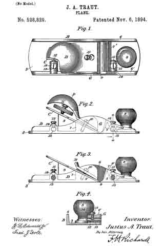
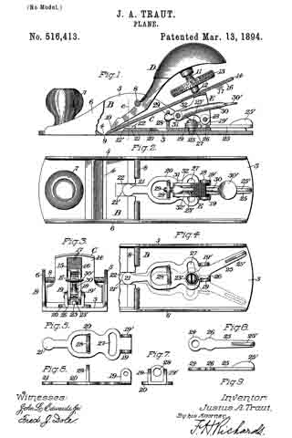
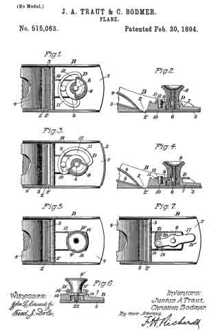
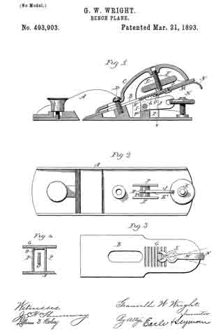
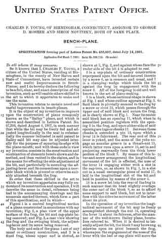
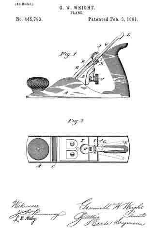
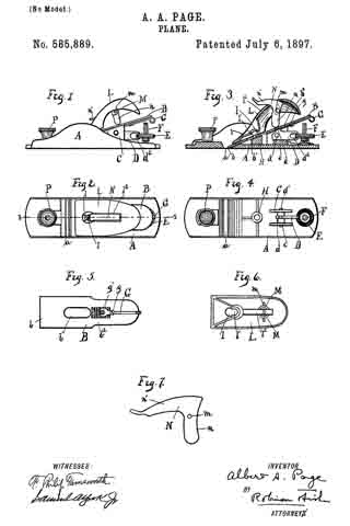
Figure 1 represents a side elevation of a plane embodying my invention; Fig. 2, a top view of the same; Fig. 3, a vertical longitudinal section on the line 3 3 of Fig. 2; Fig. A, a top view of the frame; Fig. 5, a bottom view of the plane iron or bit, Fig. 6, a corresponding view of the clamping-cap; Fig. 7, a detail of the clamping-lever.

In all the figures similar letters of reference represent like parts.

This invention relates to hand-planes; and it consists in a novel construction of parts, which when assembled produce a simple device easily regulated or adjusted.

The invention refers more particularly to an improved method of locking the plane iron or bit between the frog and the clamping-cap by means of a lever pivoted in said clamping-cap to swing vertically beyond its dead-center, as set forth and described, together with other improvements, hereinafter.

Referring to the drawings for the more particular description, A represents the stock or frame, and a the throat thereof.

B is the plane iron or bit, with b its cutting edge, the bit having a longitudinal slot b’, extending central therein, and on the under side adjacent to said slot b’ and extending lengthwise therefrom a series of teeth b2.

Mounted on the frame A is a frog C, which consists of two parallel vertical plates with diagonal upper edges, the plates being united by a block c, slotted vertically a short distance downward from its top. In the slot of the block c is pivoted by means of the pin d’ an adjusting-lever D, having on its upper side a number of teeth d, which extend slightly above the level of the frog C. The free end of said lever has a horizontal slot d2, of sufficient width to receive the edge of the adjusting-nut E, threaded to run on the vertical screw F, rigidly mounted near the end of the frame A. The edge of this nut E being knurled, it may be easily screwed up and down, and with the movement of the nut the engagement of the slot d2 of the lever D raises and lowers the free end thereof, which swings the teeth d forward or back. As the bit B is adapted to rest on the frog C, the teeth d of the adjusting-lever D engage with the teeth b2 on the under side of the bit, and the movement of the teeth produced by the adjusting-nut E on screw F is communicated to the bit, the edge of which is then forced deeper into or withdrawn from the throat a of the frame A.

Pivoted by a screw g to the under side of the bit B adjacent to the teeth b2 is a forked lever G, the fork g’ of the lever lying across the teeth b2 and the other end projecting beyond the end of the bit. This lever G is capable of swinging in a horizontal plane, and when the bit is fitted on the frog C the fork g’ is adapted to embrace the teeth d on the adjusting-lever D. When the fork g’ is thus engaged with the teeth d, which are secure against any transverse movement, the swinging of the lever G will tend to force the upper end of the bit to one side or the other, and as the bit is practically pivoted by the screw I, described hereinafter, the swinging will give a side adjustment or equalizing movement to square the cutting edge b.

Between the throat a and the frog C on the frame A is mounted the cylindrical block H, centrally bored and having a diagonal upper end corresponding to the edge of the frog C. The central bore is internally threaded for a screw I, over which the slot b’ of the bit is adapted to fit.

A clamping-cap L, the rear end of which is rounded, as shown, Figs. 1 and 3, has in its forward part a slot l, corresponding to the diameter of the head of the screw I and extending rearwardly from the slot l, a secondary slot l’ corresponding to the diameter of the shank of the screw I. A rectangular slot l2 extends centrally in the cap L, and on either side near its rear end are depending ears M. Pivoted between the ears M, by the pin m at its elbow, is a substantially right-angled lever N. One arm n of this lever is rounded to bear on the upper side of the bit B, as hereinafter described, and the other arm n’ is formed to correspond with the upper side of the clamping-cap L, as shown in Figs. 1, 3, and 7, the extreme end being flattened and widened to act as a thumb-piece, Fig. 2.

When the clamping-cap is placed over the bit B, the slot l being fitted over the screw I and the cap forced forward so that the screw is engaged in the slot l’, the right-angled lever H is used as a clamp to hold the parts together and rigidly secure them in place.

Upon the forward movement of the arm n’ the other arm n bites against the bit B, and the tendency is to force the clamping-cap L forward into closer engagement with screw I, Fig. 3.

The slight elasticity in the cast metal allows the clamping-cap to be raised as the arm n of the clamp passes the perpendicular, so that when in the position shown in Fig. 1 the parts are securely locked. The screw I may be raised or lowered to secure the right adjustment of the clamping-cap and clamp. The forward position of the clamp when the parts of the plane are locked and its conformity with the surface of the clam ping-cap makes a smooth handle and prevents the hand of the operator from being caught on the clamp when the plane is in use.

A finger-knob P is shown in the forward part of the frame beyond the throat, which may also serve as an adjusting-screw for a sliding throat-piece, as is often the case.

Having now described my invention, what I claim, and desire to secure by Letters Patent, is —

In a plane, the combination with the frame; of the bit; a support on the frame for the bit; a locking device mounted on the frame, a clamping-cap above the bit, forming the main handle portion of the plane, and having its forward end adapted to engage with said locking device to lock the forward end of the bit, while its rear end is provided with a longitudinal slot; a substantially right-angled clamp pivoted in said clamping-cap, with one arm adapted to swing forward in said longitudinal slot, and the other arm to bear on the bit and lock; the rear of the same, when the forwardly-swinging arm has assumed a position in alinement with the main portion of said clamping-cap; and means on said clamp for disengaging it from its locked position, substantially as described.

In witness whereof I have hereunto set my hand, at New Haven, in the county of New Haven, State of Connecticut, this 11th day of May, 1896.

ALBERT A. PAGE.

Witnesses:
WILLIAM T. COOKE,
CHARLES L. BALDWIN.

No. 556,114 – Core-Box Plane (Justus A. Traut) (1896)

[paiddownloads id=”525″]556114


UNITED STATES PATENT OFFICE.

_________________

JUSTUS A. TRAUT, OF NEW BRITAIN, CONNECTICUT.

CORE-BOX PLANE.

_________________

SPECIFICATION forming part of Letters Patent No. 556,114, dated March 10, 1896.
Application filed September 18, 1895. Serial No. 562,829. (No model.)

_________________

To all whom it may concern:

Be it known that I, JUSTUS A. TRAUT, a citizen of the United States, residing at New Britain, in the county of Hartford and State of Connecticut, have invented certain new and useful Improvements in Core-Box Planes, of which the following is a specification.

This invention relates to planes adapted for planing concaved surfaces of different areas, and more particularly designated as a “core-box” plane; and the object of the invention is to provide a plane having supplemental side extension-plates, whereby each or both sides of the stock can be extended to different widths and whereby the plane is rendered serviceable for finishing and planing core-boxes of a wide range of sizes, and also for use in connection with other concaved surfaces.

A further object of the invention is to provide a fastening means whereby the supplemental side extension-plates can be reversed and interchanged, or whereby they can all be secured to one side of the stock, and which fastening means is simple and easily and quickly manipulated.

In the accompanying drawings, forming part of this specification, Figure 1 is a top view of a core-box plane constructed in accordance with this invention. Fig. 2 is an interior side view of one side of the plane, the other side thereof being removed and showing the juncture of the stock in section. Fig. 3 is a transverse sectional view in line a a, Fig. 1, looking toward the right hand thereof. Fig. 4 is an end view of the plane and shows same in position for planing one-half of a the core-box of comparatively-small size, and also shows the supplemental plates removed. Fig. 5 is a view similar to Fig. 4, illustrating the plane in use upon one-half of a core-box of larger size and having a supplemental side plate in position on each side of the stock; and Fig. 6 shows the plane in use on one-half of a core-box of comparatively-large size with the supplemental side plates in position on one side of the stock.

Similar characters of reference designate like parts in all the figures of the drawings.

The plane consists, in the preferred form thereof herein shown and described, of a suitable stock or relatively-thin plate 10, preferably constructed to form two diverging side plates 11 and 12, preferably extending at right angles to each other and joined at their inner edges. Adjacent to the juncture of the side plates, and preferably substantially midway of the length thereof, the stock is provided with a mouth or mortise 13, which is preferably shown forming an acute angle, and likewise preferably has its vertex at the point of juncture of the side plates. Adjacent to the mouth 13 on the interior of the side plates and adjacent to the juncture thereof the stock has the usual inclined bed 14 for the plane-iron, formed either integrally therewith or removably secured thereon in any suitable way as desired.

The plane-iron 15, which is shown herein having an acute-angled cutting-edge, is removably and adjustably seated on the bed 14; and secured thereto by the usual fastening and clamping means, which is shown consisting of the clamping plate or wedge 16 and the thumb-screw 17. The plane-iron 15, when in its normal operative position, has its cutting-edge projecting at the desired angle below the mouth of the stock, whereby each side plate of the stock will have one-half of the cutting-edge of the plane-iron extending therein.

Adjacent to the juncture of the diverging side plates 11 and 12 on the interior of the stock a suitable toat or handle 13 is secured in any suitable way and is shown herein clamped by means of a screw 20 to a bed 19, preferably formed integral with the side plates. Adjacent to the forward end of the stock, and likewise on the interior thereof and adjacent to the juncture of the side plates, a suitable knob or hand-rest 21 is likewise secured by means of a screw 22 and bed 23 in substantially a similar way to that of securing the toat 18.

The above-described plane is commonly known as the “core-box” plane and forms no part of my present invention, except in so far as the plane constitutes a basis for the same.

Heretofore in practice when necessary to plane or finish core-boxes of different sizes it has been the usual case to provide a plane sufficiently large to plane the largest size of core-box desired to be constructed, which plane, when used in connection with core-boxes having comparatively-small diameters, is extremely clumsy to use, and when desirable to obviate this disadvantage it has been the usual practice to construct core-box planes of different sizes for work on different sizes of core-boxes, which is not only expensive but a great disadvantage when it is desired to make a number of different sizes of such boxes. In order, therefore, to obviate these disadvantages I have provided, in connection with a core-box plane of any suitable and desired construction, a suitable attachment in the nature of a guide or rest and which guide or rest is adjustable and attachable to either or both sides of the stock, as desired, and in the preferred form thereof herein shown and described preferably consists of a supplemental extension plate or plates adapted to be secured to the stock with one of its edges in parallelism with the free edge of one of the side plates forming the stock by means of a suitable fastening device. In the construction shown two of these supplemental extension-plates are provided and designated in a general way by 25 and 35. These plates may be constructed of any desired thickness and width, but are preferably constructed of about the same width as the side plates forming the stock and of sufficient thickness to permit the outer side face thereof to be in alignment with the outer side face of the adjoining side plate of the stock when the supplemental plates are in position on the stock. These plates are likewise constructed of any suitable material, but preferably of the same material as the stock, which is usually of metal, and each plate is adapted to rest on the free edge of one of the respective stock-plates 11 and 12, with one of its edges in parallelism therewith, or on the free edge of a supplemental side plate 25 or 35. As a means for securing these supplemental extension side plates in position, the side plates 11 and 12 of the stock on the interior thereof are provided with any desired number of socketed brackets 26, preferably formed integral with such side plates, and in the construction shown each side plate of the stock is provided with two of these brackets 26, one near each end thereof. These brackets are provided with clamping devices projecting through the walls and intersecting the sockets thereof at right angles thereto, and in the form shown these clamping devices are in the nature of set-screws 27, working in threaded apertures in the walls of the brackets. Removably secured in each of these socketed brackets is a bolt or bar 23, having a part thereof projecting therefrom in a plane parallel with the plane of inclination of its adjacent stock side plate.

Each supplemental extension side plate has secured thereto by any suitable means, such as by rivets, or integrally formed therewith, if desired, suitable fastening means for the bolts 28, which fastening means is preferably shown herein consisting of brackets 36. These brackets 36 are in the nature of double-socketed brackets, and are provided with bolt openings or sockets 37 adapted to receive the bolts 28, and each extension-plate preferably has the same number of brackets 36 as each stock side plate. The brackets are so disposed, relatively to each supplemental side plate, that the two sockets 37 of each bracket are in alignment with each other and with the socket of the companion bracket 26 on the stock side plates when said supplemental extension-plates are in position relatively to the side plates of the stock, and each bracket has a socket 37 adjacent to each longitudinal edge of the plate and in parallelism with the side face thereof, whereby the plates are interchangeable and reversible. These brackets are provided with clamping devices 33, one adjacent to each socket thereof, substantially similar to the clamping devices of the stock side plates and secured therein in substantially the same way, whereby either edge of a supplemental plate can rest on the free edge of the stock side plate and be secured in such position by the clamping device 38 and bolt or stud 28.

In the use of this improved core-box plane when it is desired to plane or finish a core-box of comparatively-small size the supplemental side extension-plates 25 and 35 are removed and the plane used in the ordinary way. (See Fig. 4.) When, however, a core-box of larger size is to be planed, the supplemental side plates are secured in position, one to each side of the stock, by means of the bolts 28 and clamping devices 27 and adjacent clamping devices 38, (see Fig. 5, for instance,) whereby a concaved surface of comparatively-large area can be planed, the supplemental side entension-plates 25 and 35 forming a rest or guiding means for each side of the plane. When, however, a core-box of very large size is to be planed, one of the supplemental plates, as 25, together with its bolts 28, is removed from one side of the stock and the bolts slipped into the upper sockets 37 of the brackets 36 adjacent to the upper edge of the other side-plate 35, and the side plate 25 then secured in position by means of the clamping devices 38 adjacent to such upper sockets of the plate 35, whereby the supplemental side extension-plates of the plane form a rest or guiding means when the same is used to plane or finish the core-box concavity in a manner similar to that shown. in Fig. 6. Any number of these supplemental plates may be provided with each stock, whereby many different sizes of core-boxes can be finished or planed with one plane. By means of this improved construction of supplemental extension-plates the same are interchangeable with each other, whereby they can be used on either side of the stock and also reversible relatively to the stock-plates — that is to say, either longitudinal edge of each extension-plate can be secured in position contiguous to the longitudinal edges of the stock-plates — whereby one or both sides of the stock can be built up of any desired width in accordance with the number of plates used and the requirements of the plane. Moreover, if it is desired to increase the width of the sides of the plane, when one or more extension-plates are secured on the stock, without attaching an extra plate, the bolts can be made of such length that the supplemental plates can be adjusted relatively to the side plates of the stock or to their adjoining supplemental plates to leave a space between their adjoining edges, whereby the necessity of attaching an extra plate for a slight increase of width is obviated.

By means of my improved plane it will be obvious that when a small core-box is to be finished the plane can be used with the stock simply formed by the two side plates, which side plates, in the construction shown are comparatively light and of very much less width than in the ordinary construction of stock side plates, whereby in the use of the same upon comparatively-small core-boxes the plane is light and easy to handle.

Having thus described my invention, what I claim is —

l. In a plane of the class specified, the combination of a stock constructed of two diverging plates; each of said plates having a pair of socketed brackets; a plurality of removable, interchangeable, and reversible extension-plates, each of said extension-plates having a pair of double-socketed brackets fixed thereto, the two sockets of each bracket being in alignment with each other and with a socketed bracket of one of the stock-plates, and each bracket of an extension-plate having a socket adjacent to each of its edges, whereby the extension-plates are interchangeable with each other and reversible relatively to the stock-plates, and whereby either longitudinal edge of an extension-plate can be secured in position contiguous to a stock-plate; bars or bolts removable with and independently of said extension-plates for securing said plates in position relatively to each other and to one side of the stock, to thereby increase the width of that side of said stock independently of the other side thereof, or to secure one or more of said plates to, and thereby increase the width of, each side of said stock; and fastening devices for securing said bars or bolts in position.

2. In a plane of the class specified, the combination of a stock constructed of two diverging side plates disposed at right angles to each other, and having a mouth at the juncture of said plates; a plane-iron in position adjacent to said mouth, and having its cutting-edge adapted to extend therethrough; each of said stock-plates having a pair of single-socketed brackets; a pair of removable, interchangeable, and reversible extension-plates, each of said extension-plates having a pair of double-socketed brackets fixed thereto, the two sockets of each bracket being in alignment with each other and with a socketed bracket of one of the stock-plates, and each bracket of an extension-plate having a socket adjacent to each of its edges, whereby the plates are interchangeable with each other and reversible relatively to the stock-plates, and whereby either longitudinal edge of an extension-plate can be secured in position contiguous to a stock-plate; bars or bolts removable with and independently of said extension-plates for securing said plates in position relatively to each other and to one side of the stock, to thereby increase the width of that side of said stock independently of the other side thereof, or to secure one or more of said plates to, and thereby increase the width of, each side of said stock; and fastening devices for securing said bars or bolts in position.

JUSTUS A. TRAUT.

Witnesses:
F. N. STANLEY,
H. S. WALTER.

No. 555,228 – Spokeshave And Rabbet-Plane (Justus A. Traut) (1896)

[paiddownloads id=”524″]555228


UNITED STATES PATENT OFFICE.

_________________

JUSTUS A. TRAUT, OF NEW BRITAIN, CONNECTICUT.

SPOKESHAVE AND RABBET-PLANE.

_________________

SPECIFICATION forming part of Letters Patent No. 555,228, dated February 25, 1896.
Application filed May 31, 1895. Serial No. 551,085. (No model.)

_________________

To all whom it may concern:

Be it known that I, JUSTUS A. TRAUT, a citizen of the United States, residing at New Britain, in the county of Hartford and State of Connecticut, have invented certain new and useful Improvements in Spokeshaves and Rabbet-Planes, of which the following is a specification.

This invention relates to planes, but more particularly to interchangeable spokeshaves and rabbet-planes, and the object of the invention is to provide in one device a tool commonly known as a “spokeshave” adapted to work upon forms of curved or irregular shape, and a plane commonly known as a “rabbet-plane” adapted to shave or plane rabbets in work of irregular or curved shape, and especially for working within a curved rim upon the side of a disk or plate.

A further object of the invention is to provide an improved device in connection with the interchangeable spokeshave and rabbet-plane for regulating or gaging the depth of the cut or shave to be made when the device is used as a rabbet-plane.

A further object of the invention is to also provide an implement or tool, simple and durable in construction, and which will not get out of order in the use thereof, and which is adapted, by means of its particular construction, to work with great accuracy upon many classes of material other than spokes, although the tool is ordinarily termed a “spokeshave.”

In the accompanying drawings, forming a part of this specification, Figure 1 is a view of the interchangeable tool when used as a spokeshave, showing the open side or chamber of the stock and also showing a part thereof in section. Fig. 2 is a view of the device at right angles to the view shown in Fig. 1 and having one of the handles thereof removed. Fig. 3 is a transverse section of the stock in line a a, Fig. 1, looking toward the left-hand end thereof. Fig. 4 is a view of the interchangeable tool when used as a rabbet-plane and showing it in working position on the rim of a piece of work and also showing the gage in adjusted position to regulate the depth of the shave or cut. Fig. 5 is a detached view of the cutting-knife or bit. Fig. 6 is an end view thereof. Fig, 7 is a view of the gaging device detached from the tool. Fig. 8 is an end view thereof; and Fig. 9 is a partly-sectional view taken in line b b, Fig. 3, for more clearly illustrating the recess 13.

Similar characters of reference indicate corresponding parts in the different figures.

In the preferred form thereof herein shown and described the tool or implement consists of a stock, (designated in a general way by 50,) and is preferably made of metal and of approximately cylindrical shape, whereby it is more especially adapted for work on curved or irregular surfaces.

The stock 50 is cut out or recessed to form a suitable chamber 10 and a concaved seat 11, adapted to contain and support the bit hereinafter described. Extending from end to end of the stock is a suitable slot 12, forming the mouth thereof, and which slot communicates with the interior chambered part of the stock, the lower wall of said slot forming an extension of the concaved seat 11. The interior end walls a and b of the stock are likewise recessed or cut out, as at 13, adjacent to the lower portion of the concaved seat and the mouth of the stock (see Fig. 3) to prevent the clogging of the chips between the knife and the stock.

Seated within the chamber of the stock is a bit (designated generally as 15) of any desired shape and construction suitable for the purpose for which it is to be used, and, as shown in the preferred form thereof, the bit consists of a concave-convex plate, having a shank 16 adapted to fit between the interior end walls a and b of the stock, and a blade 17 projecting beyond the sides of said shank (see Fig. 5) and adapted to work in the slotted ends of the walls and in the mouth of the stock, and extends from end to end or slightly beyond the outer end walls of the stock. (See Fig. 2.)

The convex portion 18 of the shank of the bit is seated in the concaved seat of the chamber, and is adjustably clamped therein by means of a suitable clamping or holding concavo-convex plate 19 and locking devices, preferably binding-screws 20, which project through the elongated slots 21 in the bit and extend into the screw-threaded recesses in the concaved wall of the stock. (See Fig. 1.) By tightening or loosening the binding-screws 20, extending through the elongated slots of the bit, the cutting-edge of the bit can be adjusted in the mouth of the stock to any desired position to adapt it for the work to be done. The outer wall of the approximately cylindrical stock adjacent to the mouth thereof is beveled or flattened to form the sole 22 of the stock.

The stock is provided with suitable handles 30 and 31, removably secured to the stock in any suitable way, and, as shown, the end walls of the stock are provided with suitable screw-threaded apertures into which threaded studs 23, attached to the ends of the handles, are adapted to be screwed, so that when it is desired to use the tool as a rabbet-plane or on work that requires only the use of one of the handles the opposite handle to the one to be used can be quickly and easily removed and the device used either as a spoheshave with one handle or as a rabbet-plane. (See Figs. 2 and 4.)

The particular construction of the stock and the bit, as hereinbefore set forth, in which the ends of the bit project to or slightly beyond the outer end walls of the stock, which end walls form plane bearing-faces, adapts the tool to be used as a rabbet-plane on the removal of one of the handles.

In order to regulate the depth of shave or cut of the bit when the tool is used as a rabbet-plane, a suitable gage or gaging device (designated generally as 35) of a construction adapted for the purpose to which it is to be used is provided and adjustably secured to the stock of the plane.

The gaging device, in the preferred form thereof herein shown, comprises two segmental arms 38, adapted to partially encircle the cylindrical stock and the cutting-edge of the bit, and preferably extends beyond the sole of the stock, (see Fig. 2,) each segmental arm 36, together with suitable means for adjustably securing the same to the stock — such, for instance, substantially as hereinafter set forth-constituting an independent gage for use adjacent to each end of the stock. These segmental arms 36 are preferably integrally united at their inner ends to a sliding bar or member 37, adapted to work in a groove or recess 38 in the outer wall of the cylindrical stock, by means of an elongated slot 39, through which a binding-screw 40 projects into a screw-threaded aperture in the stock. This elongated slot 39 may be of any desired length to permit the gage to be adjusted to any desired position on the stock. For instance, the slot may be extended the entire length of the sliding bar 37, if desired, to permit the tool to shave a recess in a piece of work. of a depth practically the length of the stock.

This improved device for regulating the depth of cut or shave, when the tool is used as a rabbet-plane, not only constitutes a gage but also constitutes a means for protecting the corners of the cutter when the device is used as a spokeshave; but it is obvious that, although the tool is ordinarily designated in the art as a “spokeshave,” the spoke class of work forms but a small percentage of the work upon which the tool may be used. Hence, While the gage acts to regulate the depth of cut, as above stated, when the tool, with one of its handles removed, is used as a rabbet-plane, it is also useful and necessary in connection with the device when used for other purposes than as a rabbet-plane. For instance, if desired to use both handles with the tool, and a groove or recess is to be formed in the straight edge of a board or other material, the gage might be set, as indicated at Fig. 4; or when a certain width of shave is necessary the gage can be adjusted to regulate that width, while at the same time using both handles; or when that portion of the cutter between the ends thereof is used on fine work the gaging device can be adjusted to permit one of its arms to run along the side of the board or other material and thereby act as a guide to prevent the slipping off of the tool.

From the above it will be obvious that the tool can be used as a spokeshave, as a rabbet-plane, or as a tool for many other classes of work, and when the tool is used as an ordinary spokeshave for use on spokes the gage is usually set by means of its elongated slot 39 and binding-screw 40 into the position shown in Fig. 2, and, if desired, both handles attached to the stock. When the tool is to be used for other classes of work, where it is preferably desired to use both handles, the gage is adjusted to the desired position to act as a gage or guide in accordance with the work to be done, whether that portion of the cutter adjacent to one of the outer ends or that portion of the cutter intermediate of its ends is to be used. When, however, the tool is to be used as a rabbet-plane to shave or cut a rabbet of a depth — as, for instance, shown in the work in Fig.4 — one or the other of the handles, 30 or 31, of the tool is removed according to the position of the work to be operated upon, the gage set to the position desired, and the tool is then ready for use.

By having the bit seated in the interior of the stock not only a better appearance is presented but a more rigid and firm seat is formed for the bit, and the same can be more evenly adjusted with relation to the work to be operated upon, while the chamber also forms a means for conducting the chips or shavings of the work that get between the knife edge and the mouth of the stock away from the knife edge and thereby prevents clogging thereof.

Having thus described my invention, I claim —

1. A tool of the class specified, consisting of an appronimately-cylindrical stock, whereby it is adapted to work on curved or irregular surfaces, having its end wall forming a plane bearing-face; a bit joined thereto, and having part of its cutting-blade extending to the plane of such face, whereby it is adapted to cut at the end of said stock.

2. A tool of the class specified, consisting of a chambered stock having its end wall forming a plane bearing-face, and having a mouth; a bit secured in said chamber, and having a part of its cutting-blade extending to the plane of such face, whereby it is adapted to out at the end of said stock.

3. A tool of the class specified, consisting of a chambered, approximately-cylindrical stock having its end walls forming plane bearing-faces, and having a mouth; a bit clamped in the chamber of said stock, and having its cutting-edge adjacent to said month, and having a part of its cutting-blade extending to the planes of such faces, whereby it is adapted to cut at the ends of said stock.

4. ln a tool of the class described, the combination with a chambered, approximately-cylindrical stock, the end walls thereof forming plane bearing-faces, and having a mouth extending from end to end of said stock and substantially adjacent to the plane bearing-faces thereof; of a bit adjustably clamped in the chamber of said stock, and having its cutting-blade of substantially the same length as the mouth of said stock.

5. In a tool of the class described, the combination with a chambered, approximately-cylindrical stock, the end walls thereof forming plane bearing-faces, and having a mouth extending from end to end thereof and substantially adjacent to such plane faces; of a bit adjustably clamped in the chamber of said stock, and having its cutting-blade of substantially the same length as the mouth of said stock; and a gage adjustably secured to said stock.

6. A tool of the class specified, consisting of an approximately-cylindrical stock, whereby it is adapted to work on curved or irregular surfaces, and having its end wall forming a plane bearing-face; a bit joined to the stock, and having a part of its cutting-blade extending to the plane of such face, whereby it is adapted to cut at the end of said stock; and a gage joined to said stock.

7. A tool of the class specified, consisting of a stock having both of its end walls forming plane bearing-faces; a bit joined to the stock, and having a part of its cutting-blade adjacent to each end thereof extending to the planes of such faces, whereby it is adapted to cut at either end of said stock.

8. In a tool of the class specified, the combination of an approximately-cylindrical stock, whereby it is adapted for work on curved or irregular surfaces, the end walls thereof forming plane bearing-faces; a bit adjustably clamped to the stock, and having its cutting-blade extending to the planes of such faces, whereby it is adapted to cut the ends of said stock; and handles removably secured to the ends of said stock, whereby the tool can be used as a spokeshave or as a rabbet-plane.

9. In a tool of the class specified, the combination of an approximately-cylindrical stock, whereby it is adapted for work on curved or irregular surfaces, the end walls of said stock forming plane bearing-faces; a bit adjustably clamped to the stock, and having its cutting-blade extending to the planes of such faces, whereby it is adapted to cut at the ends of said stock; a gage adjustably secured to said stock; and handles removably secured to the ends of said stock, whereby the tool can be used as a spokeshave or as a rabbet-plane.

10. In a tool of the class specified, the combination with a chambered, approximately-cylindrical stock, the end walls of which form plane bearing-faces, and having a mouth extending from end to end thereof; of a bit adjustably clamped in the chamber of said stock, and having its cutting-blade extending substantially adjacent to the planes of such faces;
and removable handles provided with screw-threaded studs adapted to enter screw-threaded apertures in the ends of the stock, whereby the tool can be used as a spokeshave or as a rabbet-plane.

11. In a tool of the class specified, the combination with a chambered, approximately-cylindrical stock, the end walls of which form plane bearing-faces, and having a mouth extending from end to end thereof, and also having a longitudinal recess in its exterior face; of a bit adjustably clamped in the chamber of said stock, and having its blade extending substantially adjacent to the planes of such faces; handles removably secured to the ends of said stock, whereby the tool can be used as a spoke-shave or as a rabbet-plane; and a gage adjustably secured to said stock, and adapted to slide in said longitudinal recess, and regulate the depth of the shave of the tool.

12. In a tool of the class specified, the combination with a chambered, approximately-cylindrical stock, the end walls thereof forming plane bearing-faces, and having a mouth extending from end to end thereof; of a bit adjustably clamped in the chamber of said stock, and having its blade extending substantially adjacent to the planes of such faces; handles removably secured to the ends of said stock, whereby the tool can be used as a spokeshave or as a rabbet-plane; and a gaging device consisting of projecting arms and a sliding bar secured thereto, and adjustably secured to and adapted to slide on said stock to regulate the depth of the shave of the tool.

13. ln a tool of the class specified, the combination with a chambered, approximately-cylindrical stock, the end walls thereof forming plane bearing-faces, and having a mouth extending from end to end thereof; of a bit adjustably clamped in the chamber of the stock, and having its blade extending substantially adjacent to the planes of such faces; handles removably secured to the ends of said stock, whereby the tool can be used as a spoke-shave or as a rabbet-plane; and a gaging device comprising segmental arms, and a sliding bar secured thereto having an elongated slot therein; and means for adjustably securing said gaging device by means of its elongated slot to the stock to permit the same to be adjusted to regulate the depth of the shave of the tool.

14. In a tool of the class specified, the combination with a chambered, approximately-cylindrical stock, the end walls of which form plane bearing-faces, and having a concaved seat therein, and a mouth extending from end to end of said stock, and also having a longitudinal recess on its exterior face; of a concavo-convex bit adapted to be adjustably clamped onto the concaved seat in the chamber of said stock, the blade of said bit extending substantially adjacent to the planes of such faces; handles removably secured to the ends of said stock, whereby the tool can be used as a spokeshave or as a rabbet-plane; a sliding bar adapted to slide in said exterior recess of the stock, and having an elongated slot therein; means for adjustably securing said bar in said recess, and segmental arms secured to said bar, and adapted to partially encircle said cylindrical stock, and adapted to regulate the depth of the shave of the tool.

15. In a tool of the class specified, the combination with a chambered, approximately-cylindrical stock, the end walls thereof forming plane bearing-faces, and having a mouth extending from end to end thereof, of a bit adjustably clamped in the chamber of said stock, and having its blade extending substantially adjacent to the planes of such faces; handles removably secured to the ends of said stock, whereby the tool can be used as a spoke-shave or as a rabbet-plane; and means adjustably secured to said stock for regulating the depth of the shave of the tool.

16. In a tool of the class specified, the combination with a chambered, approximately-cylindrical stock, the end walls of which form plane bearing-faces, and having a mouth extending from end to end thereof, and also having a flattened sole adjacent to said mouth; of a bit adjustably clamped in the chamber of said stock, the shank thereof engaging the interior end walls of the stock, and the blade thereof extending substantially adjacent to the planes of such faces, and handles removably secured to the ends of said stock, whereby the tool can be used as a spokeshave or as a rabbet-plane.

17. In a tool of the class specified, the combination of a stock; the end wall thereof forming a plane bearing-face; a bit joined to the stock, and having a part of its cutting-blade extending to the plane of such face, whereby it is adapted to cut at the end of said stock; a gage secured in position to regulate the depth of the cut of the tool; and a handle removably secured to the end of said stock, whereby the tool can be used as a spokeshave or as a rabbet-plane.

18. In a tool of the class specified, the combination of an approximately-cylindrical stock, whereby it is adapted for work on curved or irregular surfaces, the end walls thereof forming plane bearing-faces; a bit clamped to the stock, and having a part of its cutting-blade extending to the planes of such faces, whereby it is adapted to cut at the ends of said stock; and a gage consisting of a segmental arm having a bar secured thereto having an elongated slot; and means for securing said gage by means of its elongated slot to the stock, whereby it can be adjusted relatively to said stock.

19. In a tool of the class described, the combination with a chambered , approximately-cylindrical stock, the end walls thereof forming plane bearing-faces; and having a concaved seat therein and a mouth extending from end to end of said stock, and substantially adjacent to the plane bearing-faces thereof; of a concave-convex bit adjustably clamped in the chamber of said stock and onto said concaved seat, and having its cutting-blade of substantially the same length as the mouth of said stock ; and a clamping device for adjustably clamping said bit onto the concaved seat of the chamber of the stock.

20. In a tool of the class specified, the combination of a stock, the end wall thereof forming a plane bearing-face; a bit joined to the stock, and having a part of its cutting-blade extending to the plane of such face, whereby it is adapted to cut at the end of such stock; and a handle removably secured to the end of said stock, whereby the tool can be used as a spokeshave or as a rabbet-plane.

JUSTUS A. TRAUT.

Witnesses:
H. S. WALTER,
ROBT. N. PECK.

No. 553,879 – Scraping-Tool (Justus A. Traut) (1896)

[paiddownloads id=”522″]553879


UNITED STATES PATENT OFFICE.

_________________

JUSTUS A. TRAUT, OF NEW BRITAIN , CONNECTICUT.

SCRAPING-TOOL.

_________________

SPECIFICATION forming part of Letters Patent No. 553,879, dated February 4, 1896.
Application filed August 9, 1895. Serial No. 558,774. (No model.)

_________________

To all whom it may concern:

Be it known that I, JUSTUS A. TRAUT, a citizen of the United States, residing at New Britain, in the county of Hartford and State of Connecticut, have invented certain new and useful Improvements in Scraping-Tools, of which the following is a specification.

This invention relates to scraping-tools, adapted to be used for scraping or smoothing wooden surfaces — such, for instance, as surfaces of hard-wood or inlaid floors — and for other analogous purposes.

The object of my present invention is to furnish a simple, durable, and effective scraping-tool for the purpose above specified, and by means of which the scraping or smoothing of wooden surfaces may be executed with greater accuracy than is possible with the ordinary scraping-blade alone when used by hand, as heretofore common, and whereby the operation of scraping may be facilitated and rendered less tiresome to the workman.

In the operation of scraping wooden surfaces, as heretofore practiced, by means of a metal scraper-blade held in the hand, considerable difficulty has been experienced in holding the blade against the wooden surface with a uniform pressure from end to end of said blade, and to hold the blade at the required angle to secure good results and uniformity in work.

One of the chief objects of my present invention is to produce a scraping-tool that the ordinary workman may successfully manipulate and readily use in the operation of scraping or smoothing wooden surfaces, and to so construct and organize the parts of the scraping-tool that the scraper-blade may be adjusted and held at any desired angle relative to the plane of the surface being operated upon, and may be maintained at this angle during the entire operation without the exercise of skill upon the part of the workman, and whereby considerable power may be applied without material fatigue to the workman.

In the preferred form thereof herein shown and described my improved scraping-tool comprises a scraper-blade holder or frame embodying a clamp for holding a scraper-blade of said frame, a scraper-blade removably carried on said frame, a handle-bar or cross-bar preferably removably secured to the scraper-blade holder and having its ends projected beyond opposite ends of said holder, and a runner or tilting device preferably adjustably secured to the scraper-blade holder at an inclination to the scraper-blade holder and adapted for adjusting the blade to any desired angle relatively to any surface it is desired to operate upon.

In the drawings accompanying and forming part of this specification, Figure 1 is a plan view of a scraping-tool embodying my present invention. Fig. 2 is a front view of said scraper-tool as seen from the left hand in Fig. 4. Fig. 3 is a rear view of said scraper-tool as seen from the right hand in Fig. 4. Figs. 4 and 5 are end views, respectively, of the scraper-tool as seen from the right hand in Fig. 3 and showing, respectively, two different positions of the holder and scraper-blade relatively to a surface upon which the tool is supported. Fig. 6 is a rear view, similar to Fig. 3, of the scraper-blade holder and handle-bar with the adjusting-support, scraper-blade, and clamp-screws removed. Figs. 7 and 3 are side and edge views, respectively, of the scraper-blade detached.

Similar characters represent like parts in all the figures of the drawings.

The scraper-blade holder (designated in a general way by B) will usually consist of a rigid metal bearing-plate 2, having a plane inner face, which forms a bearing for the scraper-blade, and having a recess 3 in the outer face thereof, which forms a seat for the handle-bar H, which is seated in said recess, and is removably secured in place by means of a screw 4, which extends through the bearing-plate 2, as shown most clearly in Fig. 6 of the drawings.

The scraper-blade holder embodies a blade-clamp, which, in the preferred form thereof herein shown, comprises two depending clamp-arms 6 and 7, which are preferably formed integrally with the bearing-plate 2, one near each side edge of said plate, as shown most clearly in Figs. 1 to 6, inclusive, of the drawings. These depending arms overlap the plate 2 near the upper edge thereof, and have their inner bearing-faces slightly remote from, and in parallelism with, the adjacent bearing-face of the plate 2, as will be understood by reference to Figs. 4 and 5 of the drawings, the connecting portions 6’ and 7’, between the upper edge of the guiding-plate 2 and arms 6 and 7, forming abutments against which the upper edge of the scraper-blade S may abut for holding said scraper-blade against accidental vertical movement when in place between the depending clamp-arms and the bearing-face of the plate 2.

If desired, the clamp-arms 6 and 7 may be made resilient, and impinge the scraper-blade sufficiently to hold the same in place in the holder without the employment of clamp-screws; but for the purpose of positively holding the scraper-blade S in the holder B, I have shown the clamp-arms 6 and 7, provided with set-screws 8 and 9, respectively, which extend through screw-threaded holes in said clamp-arms, as illustrated in Figs. 4 and 5 in dotted line, and bear at their inner ends against the face of the scraper-blade S.

I do not limit myself to the particular construction of holder illustrated in the drawings, as the construction thereof may be modified within the scope and limits of my invention.

The scraper-blade S, which will usually be a flat sheet-metal plate, will preferably be slightly oblong in form, and will have the scraping edge beveled, as shown at 10, said blade being slightly greater in width transversely of its scraping edge than the distance between the abutments 6′ and 7′ and the lower edge of the bearing-plate 2 of the holder B, so that the scraping edge of the blade will project slightly beyond the lower edge of said holder.

As a convenient means for supporting the holder H and the blade S in the proper working position relatively to the surface (designated by the horizontal line C, Figs. 4 and 5) to be operated upon, and with the scraper-blade at the desired inclination or angle relatively to said surface, I have provided a support or runner, (designated in a general way by R,) which will preferably be adjustably secured to the scraper-blade holder B, so as to be capable of adjustment transversely of the plane of the scraping edge of the scraper-blade. This support or runner R, which may be referred to herein as the “adjusting-support,” is herein shown consisting of a rod or bar 12, carrying a roller 13 at the lower end thereof, adapted for resting upon the surface being scraped. This roller is shown carried between arms 14 and 14’ at the lower end of the bar 12, as shown most clearly in Figs. 1, 3, 4, and 5 of the drawings.

As a convenient means for adjustably securing the adjusting-support to the holder H at the proper inclination relatively to said holder and the blade carried thereby, I have shown the holder with a boss or bearing 15, formed at the upper edge thereof, approximately midway between the two clamp-arms 6 and 7, as will be understood by reference to Figs. 1 to 6, inclusive, of the drawings. This boss has a recess 16 formed therethrough, the axis of which intersects the plane of the bearing-face of the plate 2 of the holder, which recess is adapted to receive and permit a longitudinal sliding movement of the bar 12 of the adjusting-support. The degree of inclination of the recess 16 relatively to the plane of the scraper-blade carried in the holder will, of course, depend largely upon the requirements of the trade, the angle being herein shown as approximately one of thirty degrees, which I have found most convenient for general use.

As a means for adjustably securing the adjusting-support R in the bearing 15, and as a means for holding the same against rotation, I have shown the bar 12 of said support having one flat portion 18, and have shown the recess 16 of a cross-sectional shape corresponding to the cross-sectional shape of said bar, the bar being held in adjustable position in the bearing preferably by means of a set-screw 19, which extends through the boss or bearing 15 and bears at its inner end against the flat side of the bar 12 of said adjusting-support.

It will be obvious that the means for adjustably securing the adjusting-support R to the holder and the particular construction of said means and support may be variously modided without departure from my invention.

The handle-bar H is herein shown extended beyond the side of the holder B and provided with handles or knobs 20 and 20′ at opposite ends thereof, which may be grasped by the workman when manipulating a scraper-tool. This handle is made removable, so as to enable the workman to detach the same from the scraper-blade holder when it is desired to use the tool for scraping corners, &c.

When it is desired to change the inclination of the scraper-blade S relatively to a surface, as C, it is simply necessary to loosen the set-screw 19, which clamps the bar 12 of the adjusting-support R, and slide said bar upward or downward longitudinally in the bearing 15, and secure the same in adjusted position by said set-screw 19, which will increase or decrease the angle of the scraper blade and holder relatively to said surface, as will readily be understood by comparison of Figs. at and 5 of the drawings.

Having thus described my invention, I claim —

1. A scraping-tool comprehending a scraper-blade holder and a runner adjustably connected together at their upper ends for adjustment, one relatively to the other, in an intersecting plane, and diverging from their points of connection toward their opposite, lower ends; and a scraper-blade removably carried by the holder with its scraping edge extending below the lower end of the holder.

2. A scraping-tool comprehending a scraper-blade holder and a runner adjustably connected together at their upper ends for adjustment, one relatively to the other, in an intersecting plane, and diverging from their points of connection toward their opposite, lower ends; a scraper-blade removably carried by the holder with its scraping edge extending below the lower end of the holder; and a handle-bar secured to the holder with its longitudinal axis in a plane substantially parallel to the plane of the scraping edge of the scraper-blade.

3. In a scraping-tool, the combination with a scraper-blade holder having a scraper-blade supporting-face, substantially as described, and having an inclined transverse bearing at the upper end thereof; and an adjusting-support having a member adjustably carried in said bearing at an inclination to the plane of the supporting-face of said holder, substantially as described.

4. The combination with a scraper-blade holder having a scraper-blade clamp, and also having an inclined fixed bearing at the upper end thereof; of a scraper removably secured to said holder; and an adjusting-support having a bar shiftably carried in the bearing on the scraper-blade holder at a fixed inclination to the plane of the scraper-blade, and also having its lower end remote from, and in alignment with, the scraping edge of the scraper-blade, whereby the scraper-blade may be supported on the surface at an inclination to said surface, and whereby the degree of said inclination may be changed.

5. In a scraping-tool, the combination of a scraper-blade holder having a scraper-blade supporting-face, substantially as described, and also having a fixed bearing at the upper end thereof, which is inclined to the plane of the supporting-face; a supporting-bar adjustably carried in the bearing on said holders with its longitudinal axis intersecting, and at an inclination to, the plane of the supporting-face and scraper-blade holder; and a set-screw extending through one side of said bearing, and engaging the supporting-bar for holding said bar in adjusted position relatively to the holder, substantially as described.

6. In a scraping-tool, the combination of a scraper-blade holder having a scraper-blade supporting-face, substantially as described, and also having a non-circular supporting-bar receiving bearing at the upper edge thereof, the axis of which is transversely disposed and inclined relatively, to the scraper-blade holder; and a cross-sectional, non-circular supporting-bar shiftably carried in said bearing with its axis at an inclination to the plane of the supporting-face of the scraper-blade holder, and having a roller at the lower end thereof.

7. In a scraping-tool, the combination of a scraper-blade holder having a scraper-blade supporting-face, substantially as described, and also having an inclined transverse bearing at the upper edge thereof; a supporting-bar shiftably supported in said bearing at an inclination to the plane of the supporting-face of said holder; means for clamping the supporting-bar in adjusted position in said bearing; a roller carried at the lower end of said supporting-bar remote from the lower edge of the holder; a scraper-blade removably supported upon the supporting-face of the holder; a clamp carried by the holder and engaging the scraper-blade; and a handle-bar removably carried on a scraper-blade holder with its longitudinal axis in parallelism with the scraping edge of the scraper-blade.

8. A scraping-tool, comprising a scraper-blade holder and an adjusting-support adjustably secured together at their upper ends at a fixed inclination relatively to one another, and with their lower edges in alignment with, and remote from, each other; a scraper-blade removably carried by the scraper-blade holder; means for adjustably clamping the scraper-blade upon said holder; and a handle-bar removably secured to the scraper-blade-holder with its longitudinal axis in parallelism with the scraping edge of the scraper-blade.

JUSTUS A. TRAUT.

Witnesses:
CHAS. B. STANLEY,
W. J. WORAM.

No. 553,322 – Miter Or Bevel Plane (Justus A. Traut And Edmund A. Schade) (1896)

[paiddownloads id=”521″]553322


UNITED STATES PATENT OFFICE.

_________________

JUSTUS A. TRAUT AND EDMUND A. SCHADE, OF NEW BRITAIN, CONNECTICUT,
ASSIGNORS TO THE STANLEY RULE AND LEVEL COMPANY, OF SAME PLACE.

MITER OR BEVEL PLANE.

_________________

SPECIFICATION forming part of Letters Patent No. 553,322, dated January 21, 1896.
Application filed October 1, 1895. Serial No. 564,327. (No model.)

_________________

To all whom it may concern:

Be it known that we, JUSTUS A. TRAUT and EDMUND A. SCHADE, citizens of the (United States, residing at New Britain, in the county of Hartford and State of Connecticut, have invented certain new and useful Improvements in Miter or Bevel Planes, of which the following is a specification.

This invention relates to planes, more particularly of that class designated as “miter” or “bevel” planes; and the object of the invention is to provide an improved plane of this class more especially adapted for work on moldings and similar materials, whereby the same can be properly planed to permit the same to be joined with a miter or bevel joint, as desired.

The further object of the invention is to provide adjustable means in connection with and preferably embodied in the adjusting or gaging means whereby said adjustable means can be adjusted and held in engagement with the stock of the plane at whatever angle the gaging or adjusting means maybe positioned, to thereby constitute at all times a support for the material, whether the gaging means be adjusted in position adjacent to the plane-stock or not, and also to provide means in connection with such adjustable means whereby when the same is in engagement with the stock of the plane the projecting plane-iron will not strike the same, on the movement of the plane in either direction.

In the accompanying drawings, forming a part of this specification, Figure 1 is a top view of my improved miter or bevel plane, and showing a piece of work in position to have one of its ends cut at an angle of forty-five degrees, whereby, in connection with a similar molding it will form a miter-joint. Fig. 2 is a front view of the miter or bevel plane, showing the plane proper drawn away from the work. Fig. 3 is also a top view, parts thereof being broken away, and shows the gaging or adjusting means disposed at an angle of about eighty degrees relatively to the race or guideway of the plane, and also shows, in dotted lines, the adjustable means in connection with the gaging device for supporting the material in its position adjacent to the stock of the plane, and Fig. 4 is a transverse partly-sectional view, in line a a, Fig. 1, looking toward the right hand in said figure.

Similar characters designate like parts in all the figures of the drawings.

Our improved miter or bevel plane, in the preferred form thereof herein shown and described, comprises a suitable supporting means or base (designated in a general way by A) for supporting a suitable plane (designated in a general way by B) adapted to be moved to and fro thereon, a suitable adjustable gaging or adjusting means (designated in a general way by C) for supporting the work at any desired angular position relatively to the plane B, and adjustable means (designated in a general way by D) preferably embodied in the gaging or adjusting means for supporting the work in position adjacent to the plane, whether the gaging means be adjusted to a position adjacent to the plane or not, and which embodies means for preventing the plane-iron from striking said adjustable means.

The supporting means or base A may be of any desired and suitable construction adapted to support the devices above mentioned, and is provided with a race or way 10, constructed in any suitable way, in which the stock 11 of the plane B is adapted to move to and fro. Adapted to slide in this race 10 is a plane B, constructed in any suitable way to accomplish the desired object. In the form shown, however, it comprises a right-angled stock 11, one member b of which slides in the race or way 10, while the other member c thereof, which is at right angles to the supporting means A, is provided with the plane-mouth 15, hereinafter described. The members b and c may be secured together in any suitable way and reinforced by suitable ribs, as desired. Secured to this stock 11, preferably adjacent to the juncture of the members b and c thereof and in any suitable manner, but preferably by means of a bracket 12, formed integral with said stock, is a handle 13 for operating the plane. The member c of the stock is provided with a mouth 15, preferably formed at an angle relatively to the longitudinal axis of said member c. Adjacent to this mouth 15 the stock 11 in the interior thereof is provided with a suitable bracket 16 for supporting the plane-iron 14 and its adjusting and clamping mechanism, which adjusting and clamping mechanism may be, if desired, of the usual form, and hence no further description thereof is deemed neccessary. This plane-iron supporting-bracket 16, however, is also disposed at an angle relatively to the stock member c and in parallelism with the mouth 15 of the plane, and is provided with an inclined or beveled seat 16′ for the plane-iron, whereby said plane-iron 14 when in its working position will have its knife-edge projecting through said mouth 15 at an angle to the member c of the stock, whereby one part of the work will be operated upon before the other part thereof and the breaking or tearing of the fibers of the wood prevented when the plane-iron leaves the material. By means of this particular construction of plane-iron bracket the plane-iron can be made of the usual form and thickness, as in the ordinary planes, and whereby the necessity of making the plane-iron somewhat thicker at one than at the other side thereof in order to obtain an angular cut, as has heretofore been necessary, is obviated, and whereby also the sharpening of the knife-
edge of the iron is facilitated.

The gaging or adjusting means C for holding the material in proper angular position to be planed consists, in the preferred form thereof herein shown and described, of a suitable bracket 20, pivoted to the base A, preferably at the forward end thereof adjacent to the race 10, and which bracket is adapted to swing in an arc of a circle, and by the means hereinafter described support the material at any desired angle relatively to the race or member c of the plane-stock 11. This bracket 20 of the form shown is constructed of an arm 21 and a vertical plate 22, preferably integrally connected at their inner ends and diverging from each other, and through the juncture of the same the pivot screw or bolt 23 projects to pivotally secure the bracket for swinging movement relatively to the base A. This bracket-plate 22 is preferably provided with a curved inner end 24, whereby the bracket-plate 22 can be swung into any desired position adjacent to the plane-stock without the end thereof striking against the stock member c when the same is at the forward end of its race.

Preferably integral with and connecting the plate 22 and arm 21, adjacent to the outer ends thereof, is a preferably-curved member or arm 25, having an arc-shaped slot 26 therein. This arm 25 preferably extends beyond the point of juncture with the member or arm 21, and is provided at its outer end with a sleeve 27, carrying a locking device held therein by any suitable means. ln the preferable form thereof the locking device consists of a vertically-sliding bolt 28, provided with a recess (not shown) on its side face, which a pin or screw (likewise not shown) extending through the wall of the sleeve at right angles to said bolt 28 intersects, whereby the locking-bolt is permitted to have a sliding movement and is prevented from bein g drawn out. This locking-bolt 28 is provided with a suitable actuating-handle or finger-piece 20 for manipulating the same.

The base A is provided with apertures 30, disposed in an arc of a circle similar to the arc of the slotted member 25, and in position to be engaged by the lower end of the locking-bolt 28,whereby on the swinging of the bracket 20 the same can be located in any desired position by pushing the locking-bolt 28, which may be a spring-operated bolt, if desired, into any one of these apertures 30.

Any number of apertures may be provided, whereby the bracket can be located at any desired angle relatively to the race or plane stock.

In order to firmly secure the gaging or adjusting means in its adjusted position and prevent the movement thereof when the plane is in use, the bracket is provided with a supplemental fastening means in the nature of a suitable clamping device 31, and which in the form shown comprises a clamping-bolt 32, having a threaded end and an enlarged head 33, and provided with a suitable actuating-handle or sliding lever 34. The threaded end of this clamping-bolt projects through the arc-shaped slot 26 of the arm 25 and enters suitable threaded apertures 35 in the base, which apertures are likewise disposed in an arc of a circle in alignment with the locking-bolt openings 30. Any desired number of these threaded apertures may be provided. Intermediate of the upper face of the arm 25 and the under face of the enlarged head 33 a suitable washer 36 is disposed, whereby on the turning of the clamping-bolt said bracket will be clamped in the position in which the locking-bolt 28 positioned the same.

The adjustable means for holding the work in position to be operated on relatively to the plane-stop member c in the preferred form shown consists of a suitable fence or gage plate 40, adjustably secured to the bracket-plate 22 for sliding movement to and from the in movable plane. The means herein shown for securing this fence or gage plate 40 to the bracket-plate 22 comprises a suitable slot 41 in the bracket-plate 22, through which a screw-threaded stud preferably integrally secured to the fence 40 is adapted to project. A thumb-nut 43 is adapted to screw onto the end of this threaded stud to clamp the adjustable fence in any desired position, a suitable washer 44 being disposed between the inner face of the thumb-nut and bracket-plate 22.

When the bracket 20 is in the position shown — as, for instance, in Fig. 1 — the adjustable fence 40 is adjusted to permit a part of its inner end, as hereinafter described, to engage the stock member c of the plane and be clamped in such position, whereby the material can be placed in position against such fence to permit the same to be operated on by the plane. When it is desired to change the angle of the bracket 20, the same is adjusted to any desired position — for instance, as shown in Fig. 3 — in which the bracket is shown in its adjusted position at an angle of eighty degrees relatively to the race; but in order to form a proper support to hold the material in position to be planed it is necessary that the fence 40 be adjusted to have a part of its inner end engage the stock member c, the same as shown in Fig. 1. Hence, by releasing the clamping device 43 and moving the fence 40 into the position shown in dotted lines (see Fig. 3) and reclamping the fastening device the fence 40 will have a part of its inner end in engagement with the stock and in proper position to support the material. By means of this improved adjustable fence or gage plate 40 the said fence can be adjusted to permit a part of its inner end to properly engage with the stock at whatever angle the bracket 20 may be adjusted.

If, however, the entire inner end of the fence engaged the stock member c, the plane-iron in its to-and-fro movements would strike against the edge of such fence and hack the knife-edge thereof. In order, therefore, to prevent this serious disadvantage and at the same time permit the fence 40 to be adjusted into such position relatively to the stock member that it will properly support the work in position to be operated on by the plane, in whatever position the bracket 20 may be adjusted, I provide the inner end of the fence with a projection or projecting portion 44′, adapted to engage the stock member c of said plane at a point beyond the knife-edge of the plane-iron, and which in this instance is shown disposed above the upper edge of the plane-iron, whereby this projecting portion 44′ alone engages the stock of the plane when the adjustable fence is in position to support the work, and the knife-edge in the to-and-fro movements of the plane is permitted to pass by the adjacent recessed portion of the inner end of the fence, and the injury of the same thereby obviated.

It is obvious that it is advantageous to thus cause the fence to bear against the face of the plane-stock rather than, for instance, against a fixed part of the frame, as it is possible that, owing to wear, the plane may not always occupy exactly the same position relative to any lined point on the frame.

By means of this improved miter or bevel plane the work can be held at all times in proper position adjacent to the plane to be operated upon from any angle to which the bracket constituting a part of the gaging device is adjusted, and the liability of injuring the knife-edge of the plane also prevented.

Having thus described my invention, I claim —

1. In a plane of the class described, the combination with a support; of a plane movable thereon; a bracket pivoted to said support for adjustment in an angular direction relatively to said movable plane; a fence adjustable relatively to said bracket and having a projection thereon adapted to engage a portion of the movable plane, whereby the knife-edge of said plane is permitted to pass free from contact with said fence, substantially as described.

2. An adjustable gage for a plane of the class described, consisting of a bracket adapted to be pivoted adjacent to the stock of a movable plane for adjustment in an angular direction relatively to said plane, and carrying an adjustable plate or fence movable with said bracket and adjustable relatively thereto, to and from the movable plane, and having a projection thereon adapted to engage a portion of the movable plane from any position to which said bracket may be adjusted, substantially as described.

3. In a plane of the class described, the combination with a support; of a plane movable thereon; a bracket pivoted to said support for adjustment in an angular direction relatively to said movable plane and embodying a supporting plate; a fence, having a projection thereon, and secured to said supporting-plate for adjustment in parallelism therewith and movable with said bracket, whereby the projection is adapted to engage a portion of the movable plane, to permit the knife-edge of said plane to pass free from contact with said fence, substantially as described.

4. In a plane of the class described, the combination with a support havinga race or way-and also having apertures disposed in an arc of a circle; of a plane movable in said race; gaging means pivoted to said support for adjustment in an angular direction relatively to said movable plane, and comprising a bracket having a projecting arm and a vertical plate connected adjacent to their inner ends, and an arm connecting said vertical plate and projecting arm adjacent to their outer ends, and having an arc-shaped slot therein, an adj ustable locking device secured to said slotted arm, an adjustable clamping device movable in said slotted arm, said locking and clamping devices being adapted to engage apertures in the support, a fence secured to said bracket-plate and adjustable relatively thereto, and having a projection on its inner end adapted to engage the stock of the movable plane from any position to which the bracket may be adjusted, and a clamping device for securing said adjustable fence in its adjusted position, substantially as described.

5. In a plane of the class described, the combination with a support; of a plane movable thereon, and comprising a right-angled stock having a mouth therein disposed at an angle to the longitudinal axis of the plane; a plane-iron bracket secured to said stock, and also disposed at an angle to the longitudinal axis of the plane and in parallelism with the mouth of said plane; a plane-iron seated on said bracket and adapted to project through said mouth, whereby the knife-edge thereof will likewise be at an angle to the longitudinal axis of the plane; a bracket pivoted to said support for adjustment in an angular direction relatively to said movable plane; a fence adjustably connected to said bracket, and having a projection on its inner end adapted to engage a portion of the stock of the plane to permit the knife-edge thereof to pass free from contact with said fence, substantially as described.

6. In a plane of the class described, the combination with a support; of a plane movable thereon; a bracket pivoted to said support for adjustment in an angular direction relatively to said movable plane; a fence secured to said bracket for adjustment to and from the movable plane, and having a projection at its upper, inner end adapted to engage the plane-stock when said fence is adjusted into position relatively to said stock, whereby the knife-edge of the plane is permitted to pass below said projection and free from contact with the inner edge of the adjustable fence, substantially as described.

7. An adjustable gage for a plane of the class described, consisting of a bracket adapted to be pivoted adjacent to the stock of a movable plane, for adjustment in an angular direction relatively to said plane, and carrying an adjustable fence or plate movable with said bracket and adjustable relatively thereto, to and from the movable plane, and having a projection thereon adapted to engage a portion of the movable plane from any position to which said bracket may be adjusted; and means for clamping said bracket in its adjusted position, substantially as described.

8. An adjustable gage for a plane of the class described, consisting of a bracket adapted to be pivoted adjacent to the stock of a movable plane, for adjustment in an angular direction relatively to said plane; an adjustable fence or plate movable with said bracket and adjustable relatively thereto, to and from the movable plane, and having a projection thereon adapted to engage a portion of the movable plane from any position to which said bracket may be adjusted; means for adjustably clamping said fence to said bracket; and means for clamping said bracket in its adjusted position, substantially as described.

JUSTUS A. TRAUT.
EDMUND A. SCHADE.

Witnesses:
H. S. WALTER,
F. N. STANLEY.

No. 545,732 – Plane (Edmund A. Schade) (1895)

[paiddownloads id=”516″]545732


UNITED STATES PATENT OFFICE.

_________________

EDMUND A. SCHADE, OF NEW BRITAIN, CONNECTICUT.

PLANE.

_________________

SPECIFICATION forming part of Letters Patent No. 545,732, dated September 3, 1895.
Application filed June 5, 1895. Serial No. 551,754. (No model.)

_________________

To all whom it may concern:

Be it known that I, EDMUND A. SCHADE, a citizen of the United States, residing at New Britain, in the county of Hartford and State of Connecticut, have invented certain new and useful Improvements in Planes, of which the following is a specification.

This invention relates to planes, and especially to that class of tools commonly known as “smoothing-planes,” and it has for its object to provide an improved supporting and adjusting device for the plane-knife or plane-iron, whereby the same can be quickly and accurately adjusted with relation to the work to be done, and also to provide an improved clamping device for said plane knife or iron, whereby the same will be firmly held against vibration in the use of the plane.

In the drawings accompanying and forming part of this specification, Figure 1 is a vertical longitudinal section of a plane embodying my improvements, parts of said figure being shown in full lines. Fig. 2 is a plan view of a portion of the plane, illustrating certain features of the construction, a part thereof being shown in section. Fig. 3 is a transverse section taken in line a a, Fig. 1, looking toward the right hand; and Fig. 4 is a top view of the improved clamping device detached, a part thereof being broken away.

Similar characters designate like parts in all the figures of the drawings.

This improved plane, in the preferred form thereof herein shown, consists of a suitable stock or body, designated generally as 100, adapted for co-operating with those elements in which my invention particularly resides. This stock 100 is shown as provided with a suitable handle 55 at one end thereof and with the usual actuating-knob 60 at the opposite end thereof. The stock has formed in its sole the usual transverse mouth 10, the forward wall of which is designated 11 and the rearward wall as 12.

In the rear of the mouth 10 the stock is provided with a plane-iron carrier seat or support 13 of a construction suitable for the purpose herein set forth. This carrier seat or support 13 is shown as having its upper face 14 thereof preferably on a plane parallel with the sole of the stock and thereby forms a horizontal carrier-support for the plane-iron carrier-bracket and is preferably integrally connected with said stcck and extends transversely entirely across the stock, being united with the mouth of the plane by means of an inclined portion 15. This carrier seat or support 13 is somewhat thicker in cross-section than the sole of the stock to adapt it to receive the locking devices of the plane-iron or knife-carrier hereinafter described. Instead of the seat or support 13 extending entirely across the stock, the knife-carrier seat or support may, if desired, consist of a pair of longitudinal shoulders on a plane parallel with the sole of the stock and extending inwardly a short distance from the sides of the plane.

In this case, however, an intermediate horizontal support must be provided to receive the locking devices of the knife-carrier, hereinafter described. When the seat or support 13 is constructed of a solid member extending entirely across the stock, as is the preferable construction, said carrier support or seat has a recess 16 therein forming two parallel longitudinal guideways 17, Fig. 3. A knife or plane-iron carrier or bracket 20 is adjustably supported on the carrier seat or support by means of binding-screws 21, hereinafter described, and is adapted to slide in the guideways 17, and has a recess 18 in its under side to engage the guideways 17 of the carrier support or seat. This carrier-bracket is shown as having a vertically-inclined side 22 relative to the sole of the stock, adapted to receive the plane iron or knife 23, and is provided at its under side with a horizontal bearing-face parallel with the face 14 of the support 13, and is adapted to slide on said carrier support or seat. The carrier is extended below its horizontal face 14 to form a support 24 for the lower end of the knife, and is preferably V-shaped, to permit the under edge thereof to be inclined parallel with the inclined portion 15, connecting the mouth of the stock and the carrier seat or support. A suitable adjusting device for the plane-iron carrier-bracket, designated in a general way by A, is provided for adjusting said carrier-bracket and thereby the knife relative to the mouth of the stock, and is shown comprising suitable bracket-arm 26, preferably integrally connected to the stock of the plane, and in the upper end of which a threaded spindle 27, provided with a suitable thumb-nut 23, is journaled, the screw end thereof working in a suitable screw-threaded recess in the rear side of the carrier. By turning said thumb-nut the carrier-bracket will be adjusted to the desired position by sliding upon its horizontal support or seat toward or from the mouth of the stock.

In order to adjustably secure or clamp the carrier-bracket upon its seat or support 13, binding-screws 21 are preferably used and are passed through elongated slots 31 in that portion of the carrier which has its upper face in a plane parallel with the lower or seat-engaging face of the carrier-support, in order that the carrier may be moved relatively to its seat or support without effecting the positioning of the binding-screws, and to permit this the carrier is shown as having recesses 23 countersnnk therein and communicating with the inclined face 22 of said carrier. Washers 30 are disposed between the heads of the binding-screws and the horizontal upper face of the carrier-bracket, and said carrier-bracket, by means of the elongated slots 31, can be adjusted in longitudinal direction of the stock by means of the adjusting device A, hereinbefore described. By this particular construction and organization of the plane-iron or knife-supporting members of the plane iron or knife a perfect adjustment of the plane is obtained, and, moreover, a perfectly rigid support for the plane-iron or knife-carrier-bracket is provided. Any suitable means for vertically adjusting the plane-iron may be used, but is shown as comprising a lever 35, pivoted at 36 to the carrier, and having its upper end in engagement with the cap-plate 23′ for actuating the same toward and from the plane-mouth, and thereby moving the plane-iron in the same direction. This lever has the usual forked tailpiece 37 engaged by a peripheral groove in an adjusting-nut 38, which works longitudinally upon a screw or threaded post 39, fixed to the carrier.

As a means for clamping the plane-knife 23 and its usual cap-plate 23′ in position, I have provided an improved clamping device, designated in a general way by B, and which comprises a main clamping-lever having a supplemental clamping-lever connected therewith, and thereby forming a double clamping-lever, which, in the preferred form thereof, is shown consisting of a main clamping-lever 40, working on a fulcrum-screw 41, disposed on the carrier-bracket and having pivoted to its upper end the usual actuating cam-lever 42, having its cam-face 43 in operative engagement with the upper face of the cap-plate.

Pivotally connected to the main clamping-lever 40, at any suitable place thereon, and projecting beyond the lower clamping end of said lever, is a supplemental clamping-lever 45 of any suitable construction adapted for the purpose herein set forth and of comparative flexibility relative to the main clamping-lever. The main clamping-lever 40 has recesses 46, and is provided with laterally-projecting pins or studs 47, upon which the supplemental clamping-lever is adapted to swing by means of suitable ears or lugs 48, having apertures therein adapted to engage said pins or studs. As a means for adjusting this supplemental lever, the upper end thereof is provided with a suitable adjusting device, herein shown as a set-screw 49, adapted to work on the upper surface of the main clamping-lever. This supplemental clamping-lever also has an elongated aperture 51 to permit the fulcrum-stud 41 to be adjusted into position. By means of this improved clamping device, one lever of which is adapted to engage the cap-plate at a point beyond the clamping end of the other lever, the knife or plane-iron is firmly held at different points near its working end, and vibration thereof in the use of the plane is substantially eliminated.

Having thus described my invention, what I claim is —

1. In a plane, the combination with a stock, and with a plane-iron supported thereon; of a clamping device for the plane-iron comprising two clamps, one of said clamps clamping the plane-iron at a point in advance of the clamping-point of the other clamp, substantially as described.

2. In a plane, the combination with a stock, and with a plane-iron supported thereon; of a clamping device for the plane-iron comprising two clamps, one of said clamps clamping the plane-iron at a point in advance of the clamping-point of the other clamp; and means for separately operating the clamps, substantially as described.

3. In a plane, the combination with a stock; of a carrier-bracket supported thereon; a plane-iron adjustably supported on said bracket; a cap-plate adapted to rest on said plane-iron; and clamping means for said plane-iron comprising a main clamping-lever fulcrumed on the carrier-bracket and a supplemental clamping-lever pivotally adjustable on said clamping-lever and adapted to clamp the cap-plate at a point beyond the clamping-point of the main-lever, substantially as described.

4. In a plane, the combination with a stock; of a plane-iron adjustably supported on said stock; and clamping means for said plane-iron comprising a main clamping-lever fulcrumed on the stock, and a supplemental clamping-lever pivotally adjustable on said main clamping-lever, and adapted to clamp the plane-iron at a point beyond the clamping-point of the main-lever, substantially as described.

5. In a plane, the combination with a stock; of a plane-iron adjustably supported on said stock; a cap-plate adapted to rest on said plane-iron; and clamping means for said plane-iron comprising a double-lever fulcrumed to the stock, one of said levers clamping the cap-plate at a point beyond the clamping-point of the other lever, substantially as described.

6. In a plane, the combination with a stock; of a plane-iron adjustably supported on said stock; a cap-plate adapted to rest on said plane-iron; and clamping means for said plane-iron comprising a main clamping-lever fulcrumed on the stock; and a supplemental clamping-lever pivotally adjustable on said main clamping-lever and adapted to clamp the cap-plate at a point beyond the clamping-point of the main-lever, substantially as described.

7. In a plane, the combination with a stock; of a plane-iron adjustably supported on said stock; a cap-plate adapted to rest on said plane-iron; and clamping means for said plane-iron comprising a double-lever, the main clamping lever thereof being fulcrumed to the stock and the supplemental clamping-lever being pivotally adjustable on said main-lever; and means for adjusting said double-lever, whereby the adjustable action of the combined levers extends to the clamping ends of both the main and supplemental clamping-levers, substantially as described.

8. In a plane, the combination with a stock; of a plane-iron adjustably supported on said stock; a cap-plate adapted to rest on said plane-iron; a main clamping-lever fulcrumed on said stock; means for adjusting said lever; a supplemental clamping-lever pivotally adjustable on said main-lever and adapted to clamp the cap-plate at a point beyond the clamping-point of the main clamping-lever; and means for adjusting said supplemental-lever relative to the main-lever and independently thereof, substantially as described.

9. In a plane, the combination with the stock having a transverse mouth; of a horizontal carrier-support disposed thereon; and a carrier-bracket having a bearing-face substantially parallel to the horizontal face of the support, and adapted to slide on said support, and also having a vertically-inclined side adapted to support a plane-iron, said inclined side extending below the bearing-face of the horizontal support to support the plane-iron adjacent to the mouth of the stock; a plane-iron adjustably supported on said bracket; means for longitudinally actuating said carrier-bracket relatively to its support; means for adjusting the plane-iron on its inclined support; a cap-plate resting on the plane-iron; and a clamping device for said plane-iron comprising a main clamping-lever fulcrumed to the carrier-bracket; an adjusting device for said main clamping-lever; a supplemental clamping-lever pivotally adjustable on said main-lever, and adapted to clamp the cap-plate at a point beyond the clamping-point of the main-lever; and means for adjusting said supplemental-lever independently of the main-lever, substantially as described.

10. In a plane-iron, the combination with a stock; of a plane-iron adjustably supported on said stock; a cap-plate adapted to rest on said plane-iron; a main clamping-lever fulcrumed on said stock and adapted to clamp said cap-plate and plane-iron; an adjusting device for said main-lever; a supplemental clamping-lever pivoted on the main-lever at a point below the fulcrum-point of said main-lever, and adapted to clamp the cap-plate and plane-iron at a point beyond the clamping-point of the main clamping-lever; and an adjusting device for said supplemental-lever, whereby said supplemental clamping-lever is adjustable independently of the main clamping-lever, substantially as described.

EDMUND A. SCHADE.

Witnesses:
H. S. WALTER,
CHAS. B. STANLEY.

No. 540,283 – Plane (Justus A. Traut And Christian Bodmer) (1895)

[paiddownloads id=”515″]540283


UNITED STATES PATENT OFFICE.

_________________

JUSTUS A. TRAUT AND CHRISTIAN BODMER,
OF NEW BRITAIN, CONNECTICUT.

PLANE.

_________________

SPECIFICATION forming part of Letters Patent No. 540,283, dated June 4, 1895.
Application filed January 12, 1895. Serial No. 534,629. (No model.)

_________________

To all whom it may concern:

Be it known that we, JUSTUS A. TRAUT and CHRISTIAN BODMER, citizens of the United States, residing at New Britain, in the county of Hartford and State of Connecticut, have invented certain new and useful Improvements in Planes, of which the following is a specification.

This invention relates to planes, and has for its object to furnish an improved tool of this class having, in connection with the plane-iron or knife, a combined knife-actuator and knife-edge cap adapted for maintaining, when properly clamped in place, a perfect bearing between the end of the knife and said cap; and it also has for its object to furnish such a knife-controlling member, in which the knife-edge cap, as a whole, will be capable of a clamping movement independently of and relatively to the knife-actuator or main portion of such knife controlling member.

In the drawings accompanying and forming a part of this specification, Figure 1 is a side elevation, partially in section, of a portion of an ordinary smooth-plane furnished with our present improvement. Fig. 2 is a plan view of a portion of the knife-controlling member of the plane iron or knife embodying one form of our present improvement. Fig. 3 is an edge view of the cap shown in Fig. 2. Fig. 4: is a view similar to Fig. 2 and illustrating a modification of the cap shown therein. Fig. 5 is an edge view of the cap shown in Fig. 4. Figs. 6 and 8 are plan views similar to Figs. 2 and 4 for illustrating other modifications of the cap; and Figs. 7 and 9 are edge views of the forms of the cap shown in Figs. 6 and 8, respectively.

Similar characters designate like parts in all of the figures.

Our present improvement comprises a knife-controlling member for a plane-iron or knife, and having, in combination, a substantially-rigid knife-actuator, and a substantially-rigid knife-edge-cap or clamp formed integral with each other, and movable bodily, the one relatively to the other. It also comprises, in combination with said knife-actuator and the knife-edge cap, a resilient connection or spring-joint intermediate of said main portions of the knife-controlling member, and, in order to obtain a more perfect resilient relation between the knife-actuator and the knife-edge cap, the knife-engaging face of the cap, which is adjacent to said resilient connection, projects beyond the plane of the knife-engaging face of the knife-actuator, so that the knife-edge cap will have a full bearing upon the knife at both ends of said cap, and independent ofthe knife-actuator, and an oscillatory, yielding movement, transversely of the plane of the knife-controlling member, about the fulcrum or axis formed by the rear knife-engaging bearing-face or fulcrum-edge of the knife-edge cap.

We have shown, in Fig. 1, the principal portion of the body of the ordinary smooth-plane, of the class usually made of iron, and having the parts common to such planes, viz: a plane-iron or knife, a cap for the knife, a clamp for the cap, means in connection with the cap and adapted for adjusting the knife, a handle or knob at the front or left-hand end of the plane-body, and a handle (not shown), at the rearward or right-hand end of the plane-body.

In the drawings, the plane-body is designated in a general way by B, the plane-iron or knife by K, the knife-controlling member or cap by C, and the usual, forward handle, or knob, by H. This knife-controlling member or cap is shown affixed to the knife or plane-iron by means of the usual clamping screw 2; and a knife-actuating lever 3, which will be supported upon the frame or body of the plane in some usual or well known manner, is shown engaging in a mortise or slot, formed at the point 4 in the knife-controlling member, for the purpose of adjusting the knife and its controlling member together, upward or downward under the cap-engaging clamp L.

According to our present improvements, the knife-controlling member, which, as before stated, is designated in a general way by C, comprises two principal portions separated, at about the point 5, by a connection which will permit movement of one of the members, such as the knife-actuator 6, relatively to the other member, or knife-edge cap 7, in a direction transversely of the plane of said knife-controlling- member considered as a whole. This connecting member is shown herein, in the preferred form thereof, as a spring-joint, formed by a connecting portion or portions 8, of relatively-small cross-sectional area, transversely of the knife-controlling member, as compared with such area of said member at other points in the length thereof. This connection, which, in the forms of the device herein shown, constitutes a yielding or spring-joint, connects the knife-actuating portion 6 of said knife-controlling member with the knife-edge cap 7 thereof, in such a manner that these main portions are each movable, as a whole, relatively to the other, in a direction substantially transverse to the plane of said knife-controlling member, that is to say, each of said main portions has a slight, oscillatory movement, relatively to the other, about an axis intermediate of said main parts. In the manufacture of articles of this class, it has been found, that a perfect organization of the parts of a plane, — such as will bring the edge of the cap into exact parallelism with the cutting-edge of the bit- — is exceedingly difficult, owing to the liability of each member of the organization having a very slight error, when formed by the ordinary methods of manipulation. The clamping-edge of the cap, for instance, even if ground with precision, after tempering, and especially, if unevenly tempered, might not be an exact straight line in the direction of the plane of the bit, but have a slight bend in the same; and this is the frequent case in actual practice. Hence, it will be evident, that if provision is made for a slight torsional, or twisting movement of the cap, relatively to the actuator, a perfect and even bearing of the forward edge of the cap, upon the knife, will be assured.

It will be remembered that, in planes of this class, as ordinarily constructed, the cap generally employed, and which, in some of its features, is substantially similar to the knife-controlling member described herein, is required to be accurately adjusted relatively to the extreme or cutting edge 10, of the knife of the plane, so as to properly turn the shaving in the throat of the plane, as said shaving is stripped, by the knife-edge, from the body of the piece being planed. This adjustment is effected, in practice, by means of the set clamp-screw 2, the point of which is engaged in the knife-controlling member, and the shank of which travels in the usual, central, longitudinal slot in the plane-iron or knife.

When this clamp-screw is loosened, the cap may be adjusted longitudinally on the knife, with its forward end more nearly adjacent to, or more remote from, the cutting edge of the knife, and is then re-affixed to the knife by tightening said clamp-screw. The cap being properly adjusted, relatively to the knife, and the knife being also properly adjusted, with its cutting edge in the desired position relatively to the sole of the plane, this latter adjustment being effected by means of the lever 3, or other adjusting device, commonly employed for this purpose, the clamp L is then brought into locking engagement with the outer face of the cap-portion 7, of the knife-controlling member, and secured in that position, so as to hold the said clamp rigidly upon such knife-edge cap of the knife-controlling member, and thereby obtain a similar, rigid engagement between the bearing-faces 7′ and 7”, at the forward and rearward ends of the knife-edge cap, and the upper face of the plane-iron or knife, as shown in Fig. 1. The clamping force, exerted by the clamp L upon the arched knife-edge cap 7, readily springs or bends the relatively-small connecting portion, or spring joint 8, of the knife-controlling member C, thereby bringing both the forward edge 7′, of the clamp-portion or knife-edge cap of said knife-controlling member, and the rearward fulcrum edge 7”, thereof, into full bearing engagement with the plane-knife or plane-iron, so as to hold said knife and the knife-edge cap in full and proper bearing contact, the one upon the other, at all points in the transverse bearing-faces of the same, and this, notwithstanding any irregularity in the form of the actuator portion 6, of the knife-controlling member, or in the manner of fastening this actuator portion to the knife itself.

In all of the forms of our improvement, that are herein shown and described, the same general organization of parts is maintained, viz.: a knife-actuator and a knife-edge cap connected transverse to the plane of the knife-controlling member in which they are embodied, and a preferably resilient joint, intermediate of these main portions of the knife-controlling member, and forming said connection therebetween. In each case, the connecting-member, between the shaft and the actuator, is of relatively-great inherent mobility, or resilience, transversely of the knife-controlling member, as compared with the mobility, or resilience, of such cap or actuator; so that each transverse portion of the two main parts of the knife-controlling member will be of relatively-great inherent rigidity, as compared with the member which connects them.

In Fig. 2, the connection portion of the combined knife-actuator and knife-edge-clamp is shown consisting of the two edge-bars 8–8, tying together the two main portions, and at the ends of the elongated, transverse slot or opening 12. In this case these connecting bars constitute a relatively yielding portion, or spring-joint, entirely independent of the main portions of the knife-actuating member, except at the extreme lateral edges thereof; and, for the purpose of allowing this joint to operate more freely, the knife-actuator 6 will usually be slightly elevated at 6’, rearward of said joint, as shown in Fig. 3, by contrast with the dotted lines illustrating the position of the knife relatively to its controlling member, so as to isolate the relatively-narrow bearing-face 7”, of the knife-edge clamp from the body of said clamp, and from the knife-actuator, whereby a fulcrum-edge is obtained intermediate of the knife-edge cap and the knife-actuator, about which the knife-edge cap, or clamp, has a limited, oscillatory movement, relatively to the knife-actuator and independently thereof.

The other modifications of the knife-controlling member, herein shown and described, are similarly illustrated, as to their relation to the knife, in Figs. 5, 7 and 9, respectively, in all of which views, the fulcrum-edge of the rear bearing-face 7”, of the knife-edge cap is independent of the under side of the knife-actuator, and projects beyond the plane thereof.

In Fig. 4, the connection portion of the knife-controlling member is shown as a single connecting-bar, formed substantially intermediate of the lateral edges of said knife-controlling member, by recessing said edges, intermediate of the knife-edge clamp and the knife-actuator, for considerable distances inward from said edges, and in line with each other, as shown at 12, in said figure. By this organization of the knife-edge clamp and the knife-actuator with the connecting-joint 8, the two main portions of said knife-controlling member are rendered torsionally movable, relatively to each other, as well as oscillatory, relatively to each other about the connecting joint transversely of the plane of such member.

In Figs. 6 and 8 the relatively-reduced connecting portion or joint between the knife-edge clamping-cap and the knife-actuator is obtained by transversely channeling or grooving the knife-controlling member transversely thereof and intermediate of its two main portions. In Fig. 6 this channel is formed in the upper side of said knife-controlling member, while in Fig. 8 the channel is shown as being in the under side thereof.

It will be evident from the foregoing that, by organizing the knife-edge cap and the knife-actuator, so that said cap will be capable of independent, though limited, oscillatory movement in a direction substantially transverse to the plane of the knife-controlling member, said cap will be capable of exerting its clamping action upon the knife-edge entirely independently of any clamping action exerted by the knife-actuator, and that, as the clamping force of said cap is all exerted upon two relatively-narrow bearing-faces, running transversely of the knife-edge cap, an augmented clamping effect will result when the clamp L, is forced into locked engagement with said cap; also that the entire clamping force of this clamp L will be confined to the cap 7, and will be transmitted to the bearing-faces 7′ and 7” , thereof, owing to the isolation of the latter bearing-face from the under side of the knife-actuator. A perfect clamping action thus results from the organization of the several parts of the knife-controlling member in which the two main portions thereof are joined by a connection relatively more yielding, transversely of the plane of said member, than either of said portions is in a direction transversely of itself.

Having thus described our invention, we claim —

1. A knife-controlling member for a plane-iron, consisting of a relatively-independent knife – edge cap; a relatively-independent knife-actuator; and a connecting-member between, and connecting said cap and actuator, and of a relatively-great inherent mobility between, and at its points of connection to, said knife-cap and knife-actuator and transversely of the knife-controlling member, as compared with that of said cap or actuator.

2. A knife-controlling member, for a plane-iron, consisting of a relatively-independent knife-edge cap; a relatively-independent knife-edge actuator; a connecting- member between and connecting said cap and actuator, and of relatively-great inherent resilience between, and at its points of connection to, said knife-cap and knife-actuator, and transversely of the knife-controlling member, as compared with that of said cap or actuator.

3. A knife-controlling member for a plane-knife or iron, and consisting of a combined knife-edge cap and a knife-actuator formed integral with each other, and having a transverse connecting-member of relatively-small cross-sectional area, as compared with any corresponding transverse portion of the cap or actuator, substantially as described.

4. A knife-controlling member for a plane-knife or iron, and consisting of a combined knife-actuator and a knife-edge cap formed integral with said knife-actuator and having a relatively-narrow rear transverse knife-engaging bearing-face in advance of the plane of the knife-engaging face of the knife-actuator, and a transverse connecting member integral with said cap and actuator and of relatively-small cross-sectional area, as compared with any corresponding transverse portion of the cap or actuator, substantially as described.

5. A knife-controlling member for a plane-iron, and consisting of a knife-edge cap; a knife-actuator; and a connecting-member between and connecting said cap and actuator, and of relatively-great inherent torsional mobility, transversely of the knife-controlling member, as compared with that of said cap or actuator.

6. A knife-controlling member for a plane-iron, consisting of a relatively-independent knife-actuator; a relatively-independent knife-edge cap formed integral with said knife-actuator, and having a rear transverse knife-engaging bearing-face in advance of the plane of the knife-engaging face of the knife-actuator; and a connecting-member between, and connecting said cap and actuator, and of relatively-great inherent mobility, between, and at its points of connection to, said knife-cap and knife-actuator, and transversely of the knife-controlling member, as compared with that of said cap or actuator, substantially as described.

JUSTUS A. TRAUT.
CHRISTIAN BODMER.

Witnesses:
FRANCIS H. RICHARDS,
FRED. J. DOLE.

No. 536,746 – Plane (Justus A. Traut) (1895)

[paiddownloads id=”513″]536746


UNITED STATES PATENT OFFICE.

_________________

JUSTUS A. TRAUT, OF NEW BRITAIN, CONNECTICUT.

PLANE.

_________________

SPECIFICATION forming part of Letters Patent No. 536,746, dated April 2, 1895.
Application filed January 12, 1895. Serial No. 584,626. (No model.)

_________________

To all whom it may concern:

Be it known that I, JUSTUS A. TRAUT, a citizen of the United States, residing at New Britain, in the county of Hartford and State of Connecticut, have invented certain new and useful Improvements in Planes, of which the following is a specification.

This invention relates to planes, and especially to that class of tools, commonly known as smooth-planes; and it has for its object to provide an improved plane, adapted for supporting the plane-knife adjacent to the cutting end thereof, and to do this by means which are adapted for adjusting the position of the plane-knife or iron, relatively to the forward wall of the plane-mouth.

In the drawings, accompanying and forming part of this specification, Figure 1 is a vertical, longitudinal section of a smooth-plane embodying my present invention. Fig. 2 is a plan view of a portion of the plane, for illustrating certain features of construction of the same. Fig. 3 is a transverse section, taken in line a–a, Fig. 1, looking in the direction of the arrow, and Fig. 4 is a detail, sectional, plan view of an adjusting device for adjusting the position of the knife carrier, relatively to its seat in the plane.

Similar characters designate like parts in all the figures.

My present improvements comprise, in combination with a plane having a transverse mouth, a knife-carrier seat in the rear of, and inclined toward said mouth, a knife carrier supported by said seat, and having a knife-engaging face inclined toward the mouth of the plane at a relatively-greater inclination to the face or sole of the plane, than that of the knife-carrier-engaging face of the knife-carrier seat, the knife-carrier being adapted for movement along said face of its seat, means for securing the knife-carrier against movement relatively to the seat, and a knife adapted to be secured to said knife-engaging face of the carrier, so that, when the carrier is moved relatively to the forward wall of the plane-mouth, the knife itself will also be correspondingly actuated, and the area of the chip-space increased or decreased, in accordance with such movement.

My invention also comprises, in combination with the aforesaid knife-carrier and its support, means for adjusting the carrier upon, and relatively to the support, and holding the carrier in its adjusted position.

The plane-body, which is designated in a general way by B, is, or may be, in its principal features, of any ordinary or desired construction, adapted for co-operating with those elements in which my invention particularly resides, and this plane-body is shown herein, as provided with the usual handle H, at the rearward end thereof, and with the knob or actuating-handle H’, at the forward end of the same. The plane-body has formed in the face or sole thereof, the usual transverse mouth 2, the forward wall of which is designated by 2’; and, rearward of the plane-mouth, the plane-body is shown as having a knife-carrier seat or support inclined toward said mouth, and having its inclined face at a comparatively slight inclination, relatively to the face of the plane. This knife-carrier seat, which is designated herein by S, may be in the form of a solid member, extending transversely entirely across the body of the plane, or it may comprise a pair of similarly-inclined, longitudinal shoulders, extending but a short way from each of the sides of the plane, and inwardly toward the longitudinal center of the same. In the latter case, however, an intermediate, and preferably similarly-inclined member must also be provided, for a purpose which will hereinafter appear. The inclined face of this seat S, is shown herein as relatively adjacent, at its forward end, to the face or sole of the plane, and this inclined face is adapted to receive a knife carrier or bracket, designated in a general way by C, which carrier is organized to support the knife, and to be engaged and held by the seat S, to thereby prevent movement of the carrier relatively to such seat. This seat S, is much thicker at all points than the base 3, of the plane, or at least, is of a considerably greater thickness at a point a short distance in the rear of the rear wall 2” of the plane-mouth, which wall is herein shown, as formed by the forward edge of said seat. The relatively-greater thickness of this knife-carrier seat S, or of a portion of said seat, is necessary for the purpose of forming therein threaded holes, or bores 4–4, with which may engage holding means, preferably in the form of binding-screws 5–5, for securing the carrier C, to said seat.

It will be evident that, if the upper or carrier-engaging face of the seat S were in a plane parallel with the face, or sole 3′ of the frame, the forward end of the bracket would, as in the present practice, lie so far above the sole 3′, that the forward end and cutting-edge of the knife would be insufliciently supported. As the carrier-engaging face of the seat is forwardly and downwardly inclined, toward the plane-mouth, and as the forward end of the carrier-engaging face of this seat is relatively adjacent to the plane-sole or face 3’, the carrier or bracket C, will be supported with its forward end in close proximity to the extreme forward and under edge of said knife-carrier seat S, and also in close proximity to the cutting-edge of the knife or plane-iron itself, which plane-iron is designated herein by K. By this organization of the parts, it will be evident that the carrier or bracket C, will be adjustable in an oblique direction toward, and from the face or sole 3′ of the plane, and also toward and from the forward wall 2′ of the plane-mouth, so that, when the knife is drawn backward on the knife-engaging face of the carrier, and the carrier is moved downwardly on the inclined face of the seat S, to close the plane-mouth, in performing the most accurate work with the plane, the knife, or plane-iron, is supported close to its cutting-edge, as is necessary for such work. By this peculiar construction and organization of the knife-supporting members of the plane, the most perfect adjustment of the plane-knife for depth of cut, and in longitudinal direction for regulating the area of the chip-space, is obtainable, and, moreover, the most perfect possible support for the plane-knife, that is, a rigid support, most nearly adjacent to the cutting-edge of such knife, also results.

As before stated, the inclination of the carrier-supporting surface of the member S, is such that the body of said support is of considerable thickness, so that an ample thickness of metal is obtained at the line a–a, in which to form the holes 4–4, for the binding-screws 5–5; and this support is also sufficiently thick to permit the employment of screws of relatively-large bore and length, so that the carrier may be rigidly held thereby to the body of the plane.

The means for holding the plane-knife, or plane-iron K, upon the carrier, or bracket C, and for adjusting the knife, may be of any ordinary or suitable construction.

In the present case, the plane-knife is shown as resting upon the inclined, upper face of the carrier, the usual cap 8, being affixed to said knife.

A lever 9, is shown as pivoted at 9’, to the carrier C, and has its upper end in engagement with the cap, for actuating the same toward, and from the plane-mouth, and thereby moving the plane-iron in the same direction. This lever has the usual, forked tail-piece, engaged by a peripheral groove in an adjusting-nut 10, which works longitudinally upon the screw or threaded-post 12, fixed to the carrier.

The plane-knife and cap are shown as clamped in position, against the knife-supporting face of the carrier, by means of the usual clamp-lever 13, working against the fulcrum-screw 14, set into the carrier C, said clamp-lever being controlled in its clamping or releasing position, by means of the actuating cam-lever 15, pivoted at the rear end of said clamp-lever, and having its cam-face in operative engagement with the upper face of the cap 8, all of these holding devices being of ordinary construction, and well known in the art. The carrier C, is normally maintained in engagement with the upper face of the seat S, by means of the binding-screws 5–5, hereinbefore referred to, and these screws are preferably passed through a portion of the carrier, which has its upper face in a plane parallel with the lower or seat-engaging face of the carrier, in order that the carrier maybe moved relatively to seat, without affecting the positioning of these binding-screws. In order to obtain this result, the carrier is shown as having recesses, such as 17–17, countersunk therein, and formed with the end walls thereof parallel with the under side of the carrier.

The binding-screws 5–5, which preferably have washers 5′–5’, between the heads thereof and the end walls of said recesses, are also shown as passed through openings in the relatively-thin walls 13, formed by these recesses 17–17, and which openings are somewhat elongated longitudinally of the plane-body.

It will be evident that when the carrier is moved along the seat S, relatively thereto, these slots 19–19, will permit the screws to maintain their same relation to the seat S, and hold the carrier securely upon said seat. These binding-screws may be loosened, if desired, to permit this adjustment of the carrier, but this adjustment is preferably effected by means of a suitable adjusting device, such as is shown in Figs. 1 and 4 of the drawings. This adjusting device, which is designated in a general way by A, and which is shown as a cam-faced lever 20, is pivoted at its forward end, for movement in a plane coinciding with the plane of the bearing-face of the knife-carrier C, by means of a pin 21, engaging in a socket or recess 21’, in the seat S. Said lever is also shown as formed with a cam-groove 22, disposed substantially transversely of the lever and engaging the depending-lug or stud 23, on the under side of the carrier C. It will be evident that, upon the actuation of this lever 20, the carrier, engaging the cam-groove thereof, by its stud 23, will be actuated longitudinally of the plane, and the area of the chip-space correspondingly increased or decreased, by the advance of the forward edge of said carrier toward the front wall 2′ of the plane-mouth, or its recession therefrom.

After this adjustment of the carrier, the binding-screws 5–5, if loosened prior to the adjustment, will be re-tightened, and the plane-iron set in place and made ready for use. When the adjusting device for this carrier is of a sufficiently powerful character, this preliminary loosening of the binding-screws will be found unnecessary, the binding-screws having been previously so set as to hold the carrier firmly in place without entirely preventing movement of the same, the frictional engagement between said binding-screws and the carrier, and the carrier-engaging face of the seat S, being sufficient to maintain an adjustable, clamping connection between said carrier and its seat with the binding-screws.

Having thus described my invention, I claim —

1. In a plane, in combination, a plane-body having a substantially-transverse mouth, and having also a continuous-plane knife-carrier seat adjacent to, and rearward of, said mouth, and inclined vertically relatively to the plane-sole; a V-shaped knife-carrier having two independent and relatively-diverging continuous-plane bearing-faces, one of which is, throughout the length thereof, in engagement with the plane-knife, and the other of which is movably-supported substantially throughout the length thereof upon the inclined knife-carrier-seat of the plane-body; a plane-knife adjustably carried upon the upper face of said carrier, and means in connection with, and adapted for, adjusting said carrier longitudinally of, and at an inclination to the plane-sole, substantially as described, and for the purpose set forth.

2. In a plane, in combination, a plane-body having a substantially-transverse mouth, and having also a continuous-plane knife carrier-seat adjacent to and rearward of said mouth, and inclined vertically relatively to the plane-sole; a V-shaped knife-carrier adjusting-lever supported for movement in the plane of the carrier-seat and in operative engagement with, and adapted for, adjusting the knife-carrier longitudinally of said seat, and at an inclination to the plane-sole; and a knife adjustably carried upon the knife-carrier, substantially as described.

3. In a plane, the combination with a plane-body having a substantially transverse mouth, and having also an inclined knife-carrier seat adjacent to, and in the rear of said mouth and sloping toward the mouth; of a knife-carrier mounted upon said inclined seat, having a depending stud, and having also a longitudinally-slotted seat-engaging wall formed with substantially-parallel upper and lower faces; holding means, engaging the walls of said slots, and secured to the seat, and adapted to maintain the carrier in engagement with the seat, and to permit movement of said carrier upon, and relatively to the seat; an adjusting lever pivotally secured to the plane, and having a cam-groove the walls of which engage said stud upon the carrier, and adapted thereby to actuate said carrier toward, and from the plane-mouth, and a plane-knife adjustably supported upon said carrier, substantially as described.

4. In a plane, in combination, a plane-body having a substantially transverse month, and having also a continuous-plane-knife-carrier seat adjacent to and rearward of said mouth, and inclined vertically relatively to the plane-sole; a V-shaped knife-carrier having two independent and relatively-diverging continuous-plane bearing-faces one of which is, throughout the length thereof, in engagement with the plane-knife, and the other of which is movably-supported, substantially throughout the length thereof upon the inclined knife-carrier-seat of the plane-body; a plane-knife adjustably-carried upon the upper face of said carrier, and a cam-faced carrier-adjusting-lever carried below and in operative engagement with the knife-carrier, and adapted, for movement transversely of said carrier, in a plane coinciding with the plane of the knife-carrier-seat, substantially as described, and for the purpose set forth.

JUSTUS A. TRAUT.

Witnesses:
FRANCIS H. RICHARDS,
FRED. J. DOLE.

No. 533,329 – Rabbet-Plane (Justus A. Traut) (1895)

[paiddownloads id=”512″]533329


UNITED STATES PATENT OFFICE.

_________________

JUSTUS A. TRAUT, OF NEW BRITAIN, CONNECTICUT.

RABBET-PLANE.

_________________

SPECIFICATION forming part of Letters Patent No. 533,329, dated January 29, 1895.
Application filed October 8, 1894. Serial No. 525,202. (No model.)

_________________

To all whom it may concern:

Be it known that I, JUSTUS A. TRAUT, a citizen of the United States, residing at New Britain, in the county of Hartford and State of Connecticut, have invented certain new and useful Improvements in Rabbet-Planes, of which the following is a specification.

This invention relates to rabbet-planes, and it has for its principal object to furnish an improved plane of this general class, which may he readily converted from an ordinary rabbet-plane to a “bull-nose” plane without decreasing or adding to the number of parts of the tool.

Another object of the invention is to furnish an improved clamping-device for this kind of planes, by means of which the plane-iron or cutter may be securely and positively held substantially upon its longitudinal axis.

In the drawings accompanying and forming a part of this specification, Figure 1 is a side elevation of a rabbet-plane embodying my present invention. Fig. 2 is a front elevation of the same. Fig. 3 is a side elevation of a portion of the forward end or toe of the plane, looking toward the side opposite that shown in Fig. 1, and showing a reversible, auxiliary duplex runner in position to form an ordinary side-rabbet-plane. Fig. 4 is a view similar to Fig. 3, but showing the reversible member in position to form a “bull-nose” side-rabbet-plane. Fig. 5 is a transverse section taken in line x–x, Fig. 1, looking in the direction of the arrow and illustrating one use of the plane.

Similar characters designate like parts in all of the views.

In rabbet-planes as heretofore constructed it has been the practice to provide one form of plane for working in continuous open grooves, or cuts, and a separate, or “bull-nose,” plane for working in grooves or cuts closed at one or both ends thereof.

It is the main object of the present invention to combine the ordinary rabbet-plane and the “bull-nose” plane so that the two may be readily and quickly converted from one to the other, without decreasing or adding to the number of parts thereof, while at the same time maintaining the strength and solidity of the ordinary forms of plane of these types now in use. I attain this end by the provision of an auxiliary reversible member, or duplex runner removably secured to the forward end of the plane, in such a manner as to be fixedly held against movement laterally and longitudinally of the stock when in position thereon, and so that, when in either of its positions, one of the runners will have its sole in alignment with the sole of the stock, and will also have a vertical stop-face adjacent to the cutting edge of the plane-iron or cutter and adapted to close the chip-space or throat of the plane.

My invention also contemplates the provision of a clamp, adapted to be held positively in position substantially upon its longitudinal axis, so that the end thrust upon the cutter, when the plane is in use, will not loosen the clamp, but will be taken up by a fixed portion of the stock.

In the preferred embodiment of my invention, herein shown and described, P designates the stock of the plane, and is shown herein as comprising a body-portion 2, and a runner 3, of reduced cross-section, having the usual beveled face 4 sloping toward the outer side of said runner to form the usual narrow sole 5. This stock is shown herein as of substantially rectangular outline, and as provided at the upper rear end thereof with a handle 6, which may be of any desired construction. This handle is shown as formed separately from the stock and as secured thereto by a screw fastening but it is obvious that it might be integral with the stock. An oblique channel is shown, at 7, as extending from the upper, inner corner of the plane to the lower, outer corner thereof, and is adapted for maintaining the cutter or bit in position. The walls of this channel are shown as parallel with each other, and as intersecting the outer face of the plane in a line perpendicular with the sole thereof, so as to form an inner stop-wall for the outer side of the cutter-iron, and thereby maintain the cutting-edge of said iron perpendicular to the plane of the sole of the stock.

The plane-iron or bit is designated in a general way by B, and is shown as having parallel, longitudinal edges, and as adapted to lit snugly within the guides, 8 and 9, which form the upper and lower walls of the channel 7. This bit or cutter is also shown as beveled at its forward end to form a cutting edge 10, which, when the cutter is in position, will be substantially perpendicular to the sole of the stock, and is represented as beveled also adjacent to its lower, longitudinal edge, to conform with the outline of the beveled runner 3, and prevent interference with the work, which might result from the projection of a portion of the cutter beyond the inner, beveled edge of the runner.

The stock is shown herein as having formed upon its inner side a channel or guide-way 12, perpendicular to its sole but inclined to the sides of said stock at the same angle as is the channel 7, and adapted to position a clamping-device for locking the cutter against the walls of said channel 7, the two guide-ways or channels being shown as intersecting each other.

The clamping-device for securing the cutter is shown as comprising a locking-member or bridge-piece 13, having a body portion, non-contiguous to the stock, and two transverse terminal members or clamping faces, 13′ and 13”, the latter of which is disposed obliquely of the body-portion, so that when in position it will engage the inner face of the bit substantially upon the longitudinal axis thereof. This bridge-clamp is shown as provided with a central aperture or opening adapted for the reception of a clamping thumb-screw 14, the outer screw-threaded end of which engages a correspondingly-threaded aperture or tap, passing through the body portion of the plane, at a point substantially centrally-disposed relatively to the side-walls of the guide-way 12.

A washer 15 may be provided, if desired, between the head of the clamp-screw and the face of the bridge-piece.

It will be seen that, when the cutter is in position and the bridge-clamp is adjusted between the walls of the channel 12, if the body-portion of the clamp is forced or sprung inwardly toward the inner wall of the stock by the clamp-screw, all the pressure exerted will be transmitted to the two locking-faces 13′ and 13”, and that the cutter will be securely engaged and maintained in position, as the side edges of the clamp 13 engage against the walls of the guideway and fill the same so that there can be no movement of the clamp until the screw is released.

Pressure upon the cutter during the operation of the plane is transmitted to the clamp in such a way as to be received against the vertical stop-walls of the guide-way 12, and hence the clamp can not work loose.

At the forward end of the outer side of the stock, a channel or guide-way, shown at 16 as disposed substantially perpendicularly to the sole of the plane, is formed, and said channel is provided with a rearwardly-extending re-
cess or countersunk portion 16′, the transverse wall of which is described by a curve which is shown as approximately a semi-circle, but it will be understood that this recess or countersink might be of a different conformation, if desired. The forward end of the stock is shown herein as undercut to thepoint where the channel 7, or cutter-way, intersects the outer face of the plane to the sole of the runner thereof, but for only a portion of this distance.

An auxiliary reversible, member, designated in a general way by R’, and having reversible runners separately adapted to be brought into alignment with the main runner to form therewith a continuous sole, is shown herein as adapted to be seated within said channel or guide-way, and to be maintained against longitudinal movement, relatively to the stock, by the vertical stop walls, 17 and 18, thereof. This auxiliary runner is shown as of partially rectangular outline —
that is to say, it is formed with parallel front and rear walls, and with transverse parallel soles perpendicular to said front and rear walls. Said duplex runner is shown herein as having at each of its upper and lower ends a runner and a sole, designated, respectively, by 19, 19’, 20 and 20′. Each of said, runners is beveled to correspond with the beveled edge of the runner of the stock, one of said beveled faces being shown in Fig. 1. One end of this auxiliary runner is shown herein as of considerable length, and as having a toe-portion or nose, 20”, extending slightly beyond the forward end of the stock in the manner common to side-rabbet-planes as ordinarily constructed. The other end of said duplex runner is shown as having a very short runner formed by undercutting this end of the auxiliary member for a considerable distance, so that when said auxiliary member is secured to the stock in the position shown in Fig. 4, the construction willbe that of a “bull-nose” plane, the toe-portion or nose of which extends under the forward end of the stock and is but slightly in advance of the cutting edge of the bit. In order that said auxiliary runner may be properly positioned, without unnecessary adjustment thereof, I have shown the same as provided herein with an aperture or opening, extending through the same transversely thereof, at a point centrally located with respect to both the vertical, parallel outer walls and the horizontal, parallel outer walls thereof, and as secured to the stock, within the guide-way 16, by a locking device, which is shown herein as a screw 21, passing through the central opening in said stock and into a correspondingly-threaded opening therein, which latter opening is so placed as to be at the same perpendicular distance from the main sole (extended), as is the opening in the auxiliary, duplex runner from the soles 19′ and 20′. It will, be seen, therefore, that, when the auxiliary stock is secured in position by the screw 21, in either of its positions the sole of the corresponding runner will be in exact alignment with the sole of the runner upon the stock. The parallel, vertical walls of the duplex runner are so disposed as to engage snugly against the corresponding, forward and rearward stop-walls of the guide-way 16, so that longitudinal movement of the auxiliary runner, relatively to the stock, is positively prevented.

It will be understood that the laterally-extending recess 16′ is merely to form a seat for the nose 20″, and may be of any desired outline so long as it is of sufficient area to inclose the same; and also, that the outer faces of the stock and the duplex runner, when the parts are assembled form a continuous, plane surface, which presents no obstruction to the surface against which it may be held when the plane is in use, the head of the screw 21 being flush with or sunken below the outer face of the auxiliary runner, and the point of the clamping screw also being flush with the outer face of the stock.

By means of the reversible, auxiliary member just described it will be evident that, by simply removing the screw 21 and reversing the position of said auxiliary member, the plane may be quickly changed from an ordinary rabbet-plane to a “bull-nose” rabbet-plane and vice versa, without changing any of the parts thereof, so that the plane may be readily and quickly adapted for use for smoothing the sides of grooves or cuts which are continuous from end to end of the material being operated upon, or which extend but part-way along the material and are closed at their ends, which latter require a plane having a very short nose extending but slightly in advance of the cutter. It will also be noticed that the rearward, vertical wall of the auxiliary runner closes the throat of the plane and forms the forward wall of said throat in both of its positions.

A perfect convertible-plane is formed by the combination with the main stock of an auxiliary runner of the character described, whereby the plane may be adapted for use either as an ordinary rabbet-plane or as a “bull-nose” rabbet-plane, by the removal and re-setting of a single screw and the member secured thereby.

Having thus described my invention, I claim —

1. In a rabbet-plane, the combination with the stock and its runner, of an auxiliary member adapted to be secured to said stock and to close the throat of the plane and having oppositely-disposed runners separately adapted to be brought into alignment with the main runner upon the stock and form with said runner a continuous sole, substantially as described.

2. In a rabbet-plane, the combination with the stock and its runner, and with the cutter secured to said stock, of an auxiliary member adapted to be secured to the stock and to close the throat of the plane and formed with oppositely-disposed runners having respectively projecting and undercut portions forming auxiliary runners adapted to be separately brought into alignment with the main runner upon the stock and to form therewith a continuous sole, whereby said plane is adapted for use either as an ordinary rabbet-plane or as a “bull-nose” rabbet-plane, substantially as described.

3. In a rabbet-plane, the combination with the stock and its runner, and with the cutter secured to said stock, of a vertically-disposed channel or guide-way at the forward end of said stock, a reversible auxiliary member adapted to be seated in said guide-way and having oppositely-disposed long and short runners separately adapted to be brought adjacent to and to close the throat of the plane, and securing means in position and adapted for securing said auxiliary member in said guideway with the sole of either of its runners in alignment with the main sole of the stock, and thereby adapting the plane for use either as an ordinary rabbet-plane or as a “bull-nose” rabbet-plane, substantially as described.

4. In a rabbet-plane, the combination with a stock having a throat open at its forward side, and with a runner carried by said stock, of a reversible duplex auxiliary runner secured to the stock and adapted in either of its positions to close the throat of the plane and to form with the main runner a continuous runner and sole, and stops carried by said stock and adapted to prevent longitudinal movement of said auxiliary runner relatively to the stock, substantially as described.

5. In a rabbet-plane, the combination with a stock having an obliquely-disposed channel, a cutter mounted therein, and a vertically-disposed guide-way intersecting said channel, of a bridge clamp seated in said guide-way and held therein against movement longitudinally of the stock and having remotely-disposed locking-faces one of which is adapted to engage the rear wall of said guide-way and the other of which is adapted to engage the cutter substantially upon the axial line thereof, and a clamping-screw passed through said clamp and into the stock and adapted to bind said clamp to the cutter, substantially as described.

JUSTUS A. TRAUT.

Witnesses:
FRED. J. DOLE,
FREDERICK A. BOLAND.

No. 528,829 – Plane (Justus A. Traut) (1894)

[paiddownloads id=”510″]528829


UNITED STATES PATENT OFFICE.

_________________

JUSTUS A. TRAUT, OF NEW BRITAIN, CONNECTICUT.

PLANE.

_________________

SPECIFICATION forming part of Letters Patent No. 528,829, dated November 6, 1894.
Application filed April 24, 1894. Serial No. 508,812. (No model.)

_________________

To all whom it may concern:

Be it known that I, JUSTUS A. TRAUT, a citizen of the United States, residing at New Britain, in the county of Hartford and State of Connecticut, have invented certain new and useful Improvements in Planes, of which the following is a specification.

This invention relates to planes; the object of my present invention being to furnish a plane of peculiar construction and organization having a detachable part, by the removal or replacement of which, the plane may be quickly and practically adapted for use either as a rabbet-plane or as a smooth-plane.

In the drawings accompanying and forming a part of this specification, Figure 1 is a plan view of a convertible plane embodying my invention, a portion thereof being broken away, the parts being assembled to adapt the plane for use as a smooth-plane. Fig. 2 is a side elevation of the same. Fig. 3 is a side elevation of a portion of the plane with the side-plate or guard-plate removed, the plane in this condition being adapted for use as a rabbet-plane. Fig. 4 is a vertical cross-section of the plane taken in dotted line a–a, Fig. 2, looking in the direction of the arrow in said figure.

Similar characters designate like parts in all of the figures.

In the drawings I have shown my invention applied to a plane, which in general construction and organization is similar to the ordinary metallic smooth-plane. The main body or rabbet-plane body, of the plane is designated in a general way by B, and consists of the usual base or sole, 3, divided transversely by the mouth 4, forming the front and rear portions 5 and 5′, and the side-walls 6 and 6’, the one 6′ of which is herein shown as divided vertically by the mouth 4, the base or sole 3 being preferably reinforced each side of the mouth 4 by the transverse ribs 7 and 7’. The main body is usually provided at the forward end thereof (shown in Figs. 1, 2 and 3 as the right hand end) with a knob or handle, 3.

The plane-iron or cutter C which may be supported in any usual manner from below, as shown in Figs. 2 and 3, and the clamp-lever D, are, or may be, of any usual construction and organization. The cutter C is shown in the drawings as having its cutting edge in the mouth of the main body and as supported upon a longitudinal rib, 9, having an inclined face coinciding with the inclined face of the reinforced portion 7 of the base, the upper face thereof being engaged by the cutting-edge, while the forward end of the clamp-lever is held in place longitudinally by a screw, 10, extending through the forward end of said lever, through an elongated slot formed in the cutter, and entering the reinforced portion 7’ of the base.

As a means for operating the clamp-lever to clamp the cutter, a screw, 11, is provided which has a screw-threaded bearing at its upper end in the rear end of the clamp-lever, and bears at its lower end upon the rear end of the cutter, said screw usually being provided, in practice, with a wheel or disk for operating the same. It is desired to state in this connection, that these elements just described, i. e. — the cutter and its clamping devices, constitute no part of my present invention, and may be of any usual construction and organization.

As a means for rendering the plane convertible, to adapt the same to be used either as a rabbet-plane or as a smooth-plane, I have provided a guard-plate or suplementary body, G, adapted to be detachably-secured to one side of the main-body so as to cover the open side of the plane and the open end of the mouth 4, and so that the lower edge of said plate will be flush with the bottom edge of said body to guard the cutter, as most clearly shown in Figs. 2 and 3. This plate or body constitutes a guard for the open end of the mouth 4, and when secured in place, as illustrated in Figs. 1 and 2, adapts the plane for use as a smooth-plane.

As a convenient means for detachably-securing the supplementary body or guard-plate to the side of the main-body, said plate is herein shown provided at opposite ends with laterally-projecting pins,12, adapted for entering holes, 13, drilled in bosses, 14, formed upon the base 3 of the main-body, as clearly shown in Figs. 1, 2 and 3, said plate being held against lateral displacement by means of set-screws, 15, extending through the bosses 14 and impinging the retaining-pins 12 of the guard-plate. These binding-screws are herein shown as having conical ends which enter recesses formed in the peripheries of the retaining-pins of the guard-plate, and have bearings in screw-threaded transverse or vertical openings formed in the bosses 14. The retaining-pins are herein shown as separate pieces fixed to the guard-plate after the manner of rivets, but it will be obvious that said pins might constitute an integral part of said guard-plate.

The above-described construction and organization constitute an improved tool adapted for use both as a rabbet-plane and a smooth-plane, the usual open-sided mouth being provided for rabbeting when the guard-plate or supplementary plane-body is removed, and the solid, unyielding structure necessary to smooth-planing being formed when said plate or body is fastened in position upon the main-body of the plane. When set in position upon said main-body of the plane, it will be seen that the suplementary body forms the main sole-piece of the plane-body for that side of the plane adjacent to the open-sided mouth; that, by means of its peculiar connection to and organization with the main-body of the plane, said plane is braced in longitudinal direction to prevent yielding thereof, which would tend to impair or destroy the efficiency of the tool for smooth-planing; and that said plate or supplementary body, when in such set position, forms the means for rendering the body of the plane a practically unitary structure, having all the characteristics necessary to perfect operation of a smooth-plane. It will also be evident that the change from a rabbet-plane to a smooth-plane, or vice versa, may be easily and quickly effected, and that, in removing the guard-plate, the holding-devices therefor will be maintained in position upon the stock.

Having thus described my invention, I claim —

1. In a plane, the combination with a main-body having a transverse mouth open at one side of said body, of a plane-cutter extending longitudinally of said body and having a transverse cutter-edge, means for securing said cutter to the plane-body in position for use and with its cutting-edge in the mouth of the main-body, and a supplementary plane-body adapted and provided with means for connection to the open-mouth side of the main-body in fixed relation thereto and having its sole in the plane of the sole of the main-body, whereby the mouth of the main body is closed on one side thereof and the edge of the cutter is guarded, thereby converting the plane into and adapting the same for use as a smooth-plane, substantially as described.

2. In a combined rabbet-and-smooth-plane, the combination of a plane-body having a transverse mouth open at one side of said body, of a plane-cutter extending longitudinally of said body and having a transverse cutting-edge, means for securing said cutter to the plane body in position for use and with its cutting-edge in the mouth of the main-body, a guard-plate covering the open end of said mouth and having its sole in the plane of the sole of the main-body, parallel lateral pins or projections fixedly carried by said guard-plate, parallel recesses in the plane-body inclosing said pins and adapted thereby to maintain a solid connection between the forward and rearward portions of the plane-body and to prevent misalignment of the soles of the plane-body and the guard-plate, and clamping-screws engaging said pins or projections for detachably securing the guard-plate to the plane-body, substantially as described.

3. In a combined rabbet and smooth-plane, the combination of a plane-body having a transverse mouth open at one side of said body, a plane-cutter extending longitudinally of said body and having a transverse cutting-edge, means for securing said cutter to the plane-body in position for use and with its cutting edge in the mouth of the main-body, a guard-plate covering the open end of said mouth and having its sole in the plane of the sole of the plane-body, parallel lateral pins or projections peripherally recessed and fixedly carried by said guard-plate, bosses formed upon said plane-body and having parallel recesses inclosing said pins and adapted thereby to maintain a solid connection between the forward and rearward portions of the plane-body and to prevent misalignment of the soles of the plane-body and the guard-plate, and clamping-screws extending through said bosses and into the recesses thereof and having conical ends for engaging said peripheral recesses in said pins and for detachably securing the guard-plate to the plane-body, substantially as described.

JUSTUS A. TRAUT.

Witnesses:
FRED. J. DOLE,
FREDERICK A. BOLAND.

No. 516,413 – Plane (Justus A. Traut) (1894)

[paiddownloads id=”504″]516413


UNITED STATES PATENT OFFICE.

_________________

JUSTUS A. TRAUT, OF NEW BRITAIN, CONNECTICUT.

PLANE.

_________________

SPECIFICATION forming part of Letters Patent No. 516,413, dated March 13, 1894.
Application filed September 1, 1893. Serial No. 484,544. (No model.)

_________________

To all whom it may concern:

Be it known that I, JUSTUS A. TRAUT, a citizen of the United States, residing at New Britain, in the county of Hartford and State of Connecticut, have invented certain new and useful Improvements in Planes, of which the following is a specification.

This invention relates to that class of planes in which the plane-iron is adjustable for the purpose of bringing the same accurately into position for use, by means of adjusting-devices connected with the knife-holding apparatus.

The object of my present invention is to provide means, in a plane of the class specified, for adjusting the knife laterally thereof to bring the cutting-edge in parallelism with the face of the plane; and to make this adjustment by means of devices operating in connection with, but separately from (in point of time) the means for adjusting the plane-iron longitudinally thereof.

In the drawings accompanying and forming a part of this specification, Figure 1 is a side elevation, partially in section, of a plane embodying my present improvements. Fig. 2 is a plan view of the plane, with the cutter, or knife, and its clamp removed, and showing the knife holding and adjusting-apparatus in place. Fig. 3 is an end elevation of the plane, as seen from the right-hand in Figs. 1 and 2, the cutter or knife being in place, but the clamp-lever removed. Fig. 4 is a plan view of a portion of the plane illustrating the mode of operation of the swing-frame and the actuating lever therefor which regulates the lateral movement of the knife, the knife, knife-support and clamp being removed. Fig. 5 is a plan view of the swing-frame, in the preferred form thereof. Fig. 6 is a side elevation of the swing-frame, as seen from below in Fig. 5. Fig. 7 is an end elevation of the swing-frame, as seen from the right-hand in 5 and 6. Fig. 8 is a plan view of the swing-frame-adjusting lever, in a position corresponding to the same in Figs. 1 and 2; and Fig. 9 is a side view of said lever, in a position corresponding to that shown in Fig. 1.

Similar characters designate like parts in all the figures.

For illustrating the construction and mode of operation of my present improvements and the preferred manner of applying the same, I have shown the invention applied to an ordinary iron smoothing-plane. The body of the plane is designated in a general way by B, and consists of the usual base or face, 3, divided transversely by the mouth, 4, and having the side-walls, 5 and 6; it is usually provided at the forward end thereof (at the left-hand in Figs. 1, 2 and 4,) with a knob or handle, 7, and rearwardly of the plane-mouth with a transverse pin, 3, which serves as a bearing for the clamp-lever, D. The “plane-iron” or cutter, C, shown in section in Fig. 1 and in rear elevation in Fig. 3, is set in an inclined position as indicated in the drawings, and with its edge at 9, Fig. 1, extending slightly through the mouth of the plane. The cutter or knife C being supported from below in substantially the position shown in Fig. 1, the clamp-lever D is placed thereon, underneath and in engagement with the aforesaid transverse pin or bearing 8, and with its point, 10, resting on said knife near the lower end thereof, in the usual manner. The clamp-lever is or may be operated, for the purpose of clamping and unclarnping the plane-knife or cutter C, by means of the screw, 11, carried by said clamp, and bearing at its outward end, 12, against the upper side of the plane-knife, said screw being usually operated, in practice, by means of a wheel or disk, 13, fixed thereon.

The rearward and upper end, 14, of the cutter is shown having formed in its under side a channel whose edges at 15 and 16, form guides for controlling the lateral movement of the cutter, the channel having in the top thereof a series of teeth, 17, for engaging with the corresponding notches of the main lever, E, of the adjusting-apparatus. Said main-lever is shown carried by a pivot, 18, fixed in the ears, 19 and 19′, on the rearward end of a swing-frame, 20, which lies on the upper side of the face or bottom-plate 3 of the plane, and which is provided with means for the lateral adjustment thereof. Said swing-frame has at its forward end a bearing-arm, 21, which engages in a slot, 22, formed in the plane-body; said frame is held in place longitudinally of the plane by means of the screw-stud, 23, under the head of which is journaled the forward end, 24, of the lateral-adjustment lever, 25, this lever also having a bearing, 26, in working engagement between said ears 19 and 19′ of the swing-frame, and being provided at its extreme rearward end with a suitable termination, or thumb-piece, as 25′, whereby the same may be conveniently operated. The aforesaid screw-stud 23 passes down through the slot, 27 of the swing-frame, so as to control the position of said frame when this is swung laterally, as indicated by the two positions thereof shown by solid lines and dotted lines, respectively, in Fig.4. About midway of its length, the swing-frame 20, in the preferred form thereof herein shown, has a bearing, 28, for receiving the forward end, 29, of the longitudinal-adjustment lever, 30, this lever being pivoted on a stud, 31, between the forward ends of the said arms, 32 and 32′, of the aforesaid main lever E, and having its projecting rearward end properly shaped, or furnished with a thumb-piece, as 30′, whereby the same may be actuated for operating the main lever to slide the cutter forward or backward, as the case may require. It will be observed that the forward bearing 21 of the swing-frame is on the line e (Fig. 1) about midway between the clamp-lever bearing 8 and the point 10, where the knife is clamped between the end of the clamp-lever and the bottom-plate of the plane-body. The parts here described are organized, as set forth, so that when power is applied to the rearward end of the plane-knife for swinging the same laterally, said knife will naturally turn or swing upon an axis substantially coincident with said swing-frame bearing 21. Said lateral movement of the knife C is effected through the described main lever E, which engages at the upper side thereof between the said edges 15 and 16 of the channel in the knife. By this means, when the swing-frame 20 is moved laterally by means of said actuating-lever 25, the main-lever E, being mounted on said arm, is carried sidewise, being swung about the aforesaid axis 21 in substantial coincidence with the movement of the knife itself.

For adjusting the knife longitudinally thereof, the secondary lever 30 is raised or lowered, as the case may require, thereby swinging the main lever E on its pivot 18, and forcibly sliding the plane-knife under the rounded end 12 of the clamp-lever screw 11. And by operating the lever 25, the main-lever, also designated as the knife-actuator, is moved laterally to carry the knife side-wise as required. The swing-frame, by means of the combinations and construction hereinbefore described, is closely held in place on the upper surface of the base-plate 3, the forward end of the frame-actuating lever 25 serving as a washer between the head 23′ of said screw-stud and the swing-frame; the forward end 21′ of the swing-frame comes close to the under side of the knife C, so that said frame-bearing 21 is prevented from rising out of the bearing-slot 22.

Having thus described my invention, I claim —

1. In a plane, the combination with a plane-body, and with the knife and means for clamping the same in place, of a knife-supporting actuator-lever engaging the knife longitudinally and laterally thereof, an actuator-lever-carrying frame supported for movement laterally of the knife, and means for moving said actuator-lever on the frame independently of the movement of the frame, substantially as described.

2. In a plane of the class specified, the combination with the knife having the transverse notches and the longitudinal guide-edges, and with means for clamping the same in place, of a knife-supporting actuator-lever engaging said notches and between said guide-edges, a swinging actuator-lever-carrying frame supported for movement laterally of the knife, the screw-stud holding the frame in place, and a lever journaled on said stud and engaging the frame to move this independently of the movement of the actuator-lever, substantially as described.

3. In a plane, the combination with a plane-body, and with the knife and means for clamping the same in place, of a knife-supporting actuator-lever engaging the knife longitudinally and laterally thereof, a swinging actuator-lever-carrying frame supported for movement laterally of the knife, means for moving said frame laterally of the knife, and a lever fulcrumed. in the swing-frame and engaging the actuator-lever for operating this independently of the frame, substantially as described.

4. In a plane, a knife-supporting-and-adjusting device consisting of a laterally-movable frame having the ears 19 and 19′ and the fulcrum-bearing 28, combined with a main lever, substantially as described, pivotally supported between said ears and provided with a lever fulcrumed in said fulcrum-bearing, and means for holding in place and actuating said frame, substantially as described.

5. In a plane, the combination with the body having the frame-bearing slot 22 and the stud 23, of the frame 20 engaging at one end in said bearing-slot and having a transverse slot through which said stud extends, a lever on said stud and engaging the frame for moving the same laterally of the plane-body, and a knife-supporting-and-adjusting device carried on said frame and consisting of a lever pivoted thereto and furnished with means for operating the same, substantially as described and for the purpose specified.

6. In a plane, the combination with the plane-body and with the knife and means for clamping the same, of a longitudinally movable combined knife-support and actuator in engagement with the knife, an actuator-carrier supported for movement laterally of the knife, means for simultaneously moving the actuator-carrier and knife-supporting actuator laterally of the knife and means for moving said actuator independently of the movement of the actuator-carrier, substantially as described.

7. The combination in a plane, of a plane-body, a knife and means for clamping the same, a combined knife-support and actuator carried by a frame supported for lateral movement by the plane-body, means for independently operating the knife-support to shift the knife longitudinally, and means for adjusting the frame laterally of the knife, substantially as described.

JUSTUS A. TRAUT

Witnesses:
F. N. STANLEY,
CHAS. B. STANLEY.

No. 515,659 – Stop And Chamfer Plane (Alfred A. Curry) (1894)

[paiddownloads id=”503″]515659


UNITED STATES PATENT OFFICE.

_________________

ALFRED A. CURRY, OF BRIDGEPORT, CONNECTICUT.

STOP AND CHAMFER PLANE.

_________________

SPECIFICATION forming part of Letters Patent No. 515,659, dated February 27, 1894.
Application filed February 4, 1893. Serial No. 461,006. (No model.)

_________________

To all whom it may concern:

Be it known that I, ALFRED A. CURRY, a subject of the Queen of Great Britain, residing at Bridgeport, in the county of Fairfield and State of Connecticut, have invented certain new and useful Improvements in Stop and Chamfer Planes; and l do hereby declare the following to be a full, clear, and exact description of the invention, such as will enable others skilled in the art to which it appertains to make and use the same.

My invention has for its object to produce a chamfering and molding plane that will out a stop without change of position of the cutter by the same movement that the chamfer or molding is cut, thereby doing away with the necessity of using a chisel or other tool to out stops at the end of the molding or chamfer, or with the use of a tool held in a vertical position to scrape the surface of the molding or chamfer after it has been roughened out by a routing tool. It will be seen therefore that my novel tool performs the functions both of a router and a finishing tool, in addition to cutting both stops.

In the accompanying drawings forming part of this specification Figure 1 is a perspective of my novel plane adjusted for use as a chamfer plane, the mouth piece being in section; Fig. 2 a section on the line y y in Fig. 3; Fig. 2a an inverted plan view of the forward end of my novel plane corresponding with Fig. 2; Fig. 3 a section on the line x x in Fig. 2. Figs. 4 and 7 are elevations of different forms of mouth pieces; Figs. 5 and 8 elevations illustrating cutters corresponding therewith; Fig. 6 a section on the line z z in Fig. 4 the cutter also being shown in edge view 5 Fig. 9 a section on the line m m in Fig. 7 the corresponding cutter also appearing in section; Fig. 10 a view of a molding and stop made by the cutter illustrated in Fig. 5; Fig. 11 a view of a molding and stop made by the cutter illustrated in Fig. 8, and Fig. 12 is a view of still another form of molding and stop, the latter being made by the same cutter which cuts the molding, as in the other forms.

A denotes the body of the plane as a whole, and 2 denotes the handle. These parts may be of any ordinary or preferred construction adapted to this class of work. In the plane illustrated in the drawings 3 denotes the side plates, 4 the front plate, and 5 the incline of the cutter box or blade holder, and 6 and 7 are the angle plates which engage the sides of the piece of wood to be chamfered. Angle plate 7 is not as long as angle plate 6 and terminates in a horizontal plate 8, said plate being formed integral with depending holders 9, which receive rods 10, said rods carrying at their inner ends a side gage 11 the inner face of which corresponds with the inner incline of plate 7 and the top corresponding with the under side of the horizontal plate. The adjustment of the side gage determines the depth of the cut made by the cutter in forming the chainfer or molding.

12 denotes set screws which engage rods 10 to lock the side gage in position after adjustment.

13 denotes the cutter or blade, the cutting edge of which is of course shaped to correspond with the shape of the chamfer or molding it is desired to produce, a straight edge of course producing a straight chamfer and an inwardly or outwardly curved edge producing a corresponding curve in the piece of wood that is operated upon. The cutter is held in position by the usual lever 14 which has its fulcrum on a transverse pin 15 and is provided at its upper end with a set screw 16 which is adapted to bear against the upper end of the cutter and when turned downward upon the cutter raises the upper end of the lever thereby forcing the lower end of the lever down upon the lower end of the cutter and clamping it in place.

It will be seen from Figs. 2 and 2a that the cutter or blade is not used in the ordinary way, that is with the beveled side down. In my improved plane the cutter is used with the face side down the bevel being upon the upper side so that in use I cut away the wood that is to be removed instead of scraping it away. In use the cutter or blade rests upon the incline there being no open space whatever back of or under the cutter.

17 denotes the mouth piece which I have shown as provided with side lips 18 to engage the side plates 3 of the cutter box with a lug 19 on the top through which a set screw 20 passes, said set screw engaging the top of the front plate to adjust the mouth piece, and with a slot 21 through which a set screw 22 passes which engages the front plate to lock the mouth piece in position after adjustment. The essential feature of the mouth piece is that it is provided with an operative face 23 which in all cases corresponds exactly with the curvature of the cutting edge. If the cutting edge is a convex curve, as in Fig. 5 producing a concave curve in the molding as in Fig. 10, the operative face of the mouth piece is extended outward from the vertical plane of the body thereof as clearly shown in Fig. 6. If the cutting edge is a concave curve as in Fig. 8 producing a convex curve in the molding as in Fig. 11, the operative face of the mouth piece extends inward from the vertical plane of the body thereof as clearly shown in Fig. 9.

By making the cutter box part of the body, i. e., stationary, and dispensing entirely with a front gage using a side gage in lieu thereof, I insure that the plane in use shall wear evenly from front to back. Where a front gage is used the wear is at the back of the plane which greatly shortens its life. The cutter when once adjusted does not require to be shifted in changing from one kind of work to another, the thickness of the shaving in all kinds of work being regulated by the adjustment of the mouth piece.

In use the operator selects the proper cutter to produce the molding or chamfer required, and having placed it in position with the face side down and the bevel up and locked it there, he adjusts the mouth piece to cut as thick a shaving as the quality or hardness of the wood will warrant. In case the molding is very small or the chamfer shal-
low it will be necessary to set the side gage inward. To cut a stop and a chamfer or molding the operator simply places the cutting edge at the point in the piece of wood to be operated upon where the stop is to commence and presses firmly downward and forward taking care to stop the tool before the end of the chamfer or molding is reached. He then repeats the operation from the other end, these two operations serving as a matter of fact to complete perfectly both stops and the chamfer or molding.

The side gage is to be used with a knife having either a straight cutting edge or an edge of any desired configuration. It is not necessary that the chamber should be perfectly symmetrical on each side of its center as it may be of a variety of forms and these may be secured by using a knife having a curved cutting edge and by adjusting the side gage more or less inwardly.

Having thus described my invention, I claim —

1. A chamfer plane comprising the body formed of the angle plates 6, 7, the inclined plate 5 with the side plates 3, 3, rigidly connected thereto the cross or front plate 4 connecting the side plates and constituting with them the box, the cutter arranged in said box and projecting under the front plate 4 and the vertically adjustable mouth piece carried by the said front plate 4, substantially as described.

2. In combination, the body comprising the angle plates 6, 7 with the incline 5 and the side plates 3, the cross or front plates 4 between the front ends of the side plates and constituting therewith the box of the plane, the knife arranged in the box, and the mouth plate secured adjustably to the front side of the box and having lips extending around the front corners of the box, substantially as described.

3. In combination in a chamfer plane, the angle plates 6 and 7 rigidly connected together forming a solid body portion, the knife adjustably carried by the said solid body part, one of said angle plates having a recess in its inner face, the adjustable side gage adapted to said recess to present a flush surface with the face of the recessed angle plate and movable transversely across the angular space, and the means for adjusting and holding said side gage, substantially as described.

4. In combination the angle plates 6 and 7, the knife having its front cutting edge extending to the front end of the angle plates, and the mouth plate also arranged at the front end of the angle plates above the cutting edge, said mouth plate consisting of a flat piece arranged vertically being adjustable vertically of the front end of the plane said angle plates constituting the gage frame and being free from projecting portions forward of the cutting edge, substantially as described.

5. A chamfer plane comprising the body formed of the angle plates, the side plates and the inclined plate rigidly connected thereto, the cross or front plate 4 constituting with them the box, the cutter arranged within said box projecting under the front plate and having a cutting edge adapted to form a rib or depression and the mouth piece carried by the front plate it and having a projection at its lower end extending substantially at right angles to the body of the mouth piece and conforming to the cutting edge, substantially as described.

In testimony whereof I affix my signature in presence of two witnesses.

ALFRED A. CURRY.

Witnesses:
A. M. WOOSTER,
P. M. REYNOLDS.

No. 515,063 – Plane (Justus A. Traut And Christian Bodmer) (1894)

[paiddownloads id=”502″]515063


UNITED STATES PATENT OFFICE.

_________________

JUSTUS A. TRAUT AND CHRISTIAN BODMER, OF NEW BRITAIN,
CONNECTICUT; SAID BODMER ASSIGNOR TO SAID TRAUT.

PLANE.

_________________

SPECIFICATION forming part of Letters Patent No. 515,063, dated February 20, 1894.
Application filed August 9, 1893. Serial No. 482,771. (No model.)

_________________

To all whom it may concern:

Be it known that we, JUSTUS A. TRAUT and CHRISTIAN BODMER, citizens of the United States, residing at New Britain, in the county of Hartford and State of Connecticut, have invented certain new and useful Improvements in Planes, of which the following is a specification.

This invention relates to adjustable-mouth planes, the object being to furnish means for adjusting the mouth-slide and for holding the same in place.

In the drawings accompanying and forming a part of this specification, Figure 1 is a plan view of a portion of a plane furnished with our present improvements. Fig. 2 is a sectional side view of the plane. Figs. 3 and 4 are views similar to Figs. 1 and 2, respectively, for illustrating the mode of operation of the improvement. Fig. 5 is a view-similar to Fig. 1, showing a modification of the improvement. Fig. 6 is a sectional side view of a portion of the same. Fig. 7 is a view similar to Fig. 1, showing another modiication.

Similar characters designate like parts in all the figures.

Referring to Figs. 1, 2, 3 and 4, the letter B designates the forward portion of an ordinary iron smoothing-plane of the class which are usually provided with a mouth-slide, also sometimes designated as an “adjustable front,” for regulating the width of the mouth 2, of the plane. The usual plane-iron or cutter is shown in place at 3, held under the forward end of the ordinary clamp, 4, in a well known manner.

The mouth-slide designated by 5, is shown provided with a stud, 6, preferably rigidly fixed therein as indicated in Figs. 2 and 4. Said stud 6 extends upward through the forward end, 7, of the plane-frame, and is provided on its threaded upper end with a clamping nut, 8, whereby to hold the mouth-slide in place.

According to our present improvements, the plane is furnished with a mouth-slide actuator, designated in a general way by D, and whose principal portion constitutes an adjustable block or thrust member, designated by 9, intermediate to some part of the mouth-slide and a suitable fixed stop-abutment, as, for instance, the pin 10, on the plane-frame. In the preferred form thereof shown in Figs. 1 to 4 inclusive, said actuator consists, essentially, of an eccentric disk 9; this is shown provided with a loop or outer bar, 11, bearing against the opposite side of the aforesaid abutment-pin 10, as clearly shown in said figures. By turning the actuator D toward the right-hand or left-hand, as for instance from the position shown in Figs. 1 and 2 to that shown in Figs. 3 and 4, the mouth-slide will be moved, in the present instance toward the right-hand for widening the open space, 2′ , between said slide and the cutter 3, as will be seen by comparison of said figures of the drawings. The actuator D, being set on the plane-frame underneath the clamp-nut 8, is thereby rigidly held in place when said nut is screwed down for holding the mouth-slide.

The actuator D is shown pivotally supported on the stud 6 of the month-slide 5, so that in connection with the actuator slot 12, and the abutment-pin 10, said actuator holds the mouth-slide positively against movement in either direction; said abutment-pin fitting closely but freely within said slot, and the forward and rearward sides of said pin constituting oppositely-disposed stop-abutments.

In Figs. 5 and 6 we have shown a modification of the invention, in which the actuator, here designated by D’, consists of an eccentric disk 9’, which fits on the clamp-screw 8’, and works between the forward and rearward abutrnents 14 and 15, of the plane-frame (see Fig. 6) so as to control the position of the mouth-slide in substantially the same manner as described in connection with Figs. 1 to 4 inclusive. Said disk 9′ is shown furnished with a knurled rim 16, whereby the operator may conveniently turn the actuator for adjusting the mouth-slide.

In Fig. 7 there is shown a further modification of the improvement, in which the actuator D” consists of a flat lever 17, fitted over the stud 6, (this being the same as the one shown in Figs. 1 to 4 inclusive) and having a pin or stud, 18, fitting in an eccentric groove, 19, between the forward and rearward abutments 20 and 21, formed on the plane-frame and corresponding to those shown in Figs. 5 and 6 and also (in reverse order) to the forward and rearward sides of the abutment-pin 10 shown in Figs.1, 2, 3 and 4. In Fig. 7, the clamp-nut is omitted for the purpose of more clearly illustrating the other features; but it is or may be the same as the one shown in Figs. 2 and 4. In Figs. 5 and 6, the clamp-screw 22 is shown formed integral with the head 8’, and in working engagement with the corresponding internal thread of the mouth-slide, as will be understood from Fig. 6.

Having thus described our invention, we claim —

1. In a plane, in combination, aplane frame having a stop-abutment upon the upper face thereof, a mouth-slide having a fixed stem, vertical thereto, an independently operable mouth-slide actuator supported upon the upper face of the plane-frame and engaging the stem and stop-abutment so as to rotate about said stem and against said abutment, and means for clamping said actuator against the plane-frame, substantially as described.

2. In a plane, in combination, the plane-frame having an abutment or stop upon the upper face thereof, a mouth-slide, a stern fixed at one end to the mouth-slide and having a clamp-nut adjustably secured to its opposite end, an independently operable eccentric loosely carried by the stem intermediate to the upper face of the frame and the clamp-nut and in engagement with the abutment, substantially as described and for the purpose set forth.

JUSTUS A. TRAUT.
CHRISTIAN BODMER.

Witnesses:
G. W. TRAUT,
H. C. HINE.

No. 512,084 – Bench-Plane (Granville W. Wright And Albert A. Page) (1894)

[paiddownloads id=”499″]512084


UNITED STATES PATENT OFFICE.

_________________

GRANVILLE W. WRIGHT AND ALBERT A. PAGE, OF NEW HAVEN, CONNECTICUT,
ASSIGNORS TO THE SARGENT & COMPANY, OF SAME PLACE.

BENCH-PLANE.

_________________

SPECIFICATION forming part of Letters Patent No. 512,084, dated January 2, 1894.
Application filed May 15, 1893. Serial No. 474,270. (No model.)

_________________

To all whom it may concern:

Be it known that we, GRANVILLE W. WRIGHT and ALBERT A. PAGE, of New Haven, in the county of New Haven and State of Connecticut, have invented a new Improvement in Bench-Planes; and we do hereby declare the following, when taken in connection with accompanying drawings and the letters of reference marked thereon, to be a full, clear, and exact description of the same, and which said drawings constitute part of this specification, and represent, in —

Figure 1, a view in side elevation of one form which a plane constructed in accordance with our invention may assume; Fig. 2, a plan view thereof; Fig. 3, a view thereof in central vertical longitudinal section on the line a–b of Fig. 2; Fig. 4, a view of the plane in transverse section on the line c–d of Fig. 3; Fig. 5, a view in transverse section through the stock of the plane on the line e–f of Fig. 1; Fig. 6, a detached view through the clamp of the plane on the line g–h of Fig. 2; Fig. 7, a detached plan view of the box or housing; Fig. 8, a similar view thereof in side elevation; Fig. 9, a detached reverse plan view of the secondary adjusting lever.

Our invention relates to an improvement in bench-planes, the object being to produce at a low cost for manufacture, a simple, light, durable and convenient article.

With these ends in view, our invention consists in a bench-plane having certain details of construction as will be hereinafter described and pointed out in the claims.

In carrying out our invention we form a stock A, from a single piece of heavy sheet-metal, which is struck into the required shape, the stock having the usual side flanges A’, and in addition thereto upturned end flanges A2 A2, into which the side flanges merge, as clearly shown by Figs. 1, 2 and 3 of the drawings. The stock thus formed will naturally have rounded side and end corners a, as shown in Figs. 4 and 5 of the drawings, that being an advantageous form, as such corners are less liable to mark or mar the article being planed than the sharp corners of planes having their stocks cast. The said stock is constructed with a transverse slot A3, located in the usual place, its rear wall of being beveled, as shown by Fig. 3 of the drawings.

Within the stock we locate a box or housing B, which we preferably strike up from a single piece of sheet-metal. This box may be said to be U-shaped in transverse section, and is arranged with its open side downward, as shown in Fig. 4 of the drawings, its edges being furnished with projecting lugs b b, by means of which it is secured to the stock A, the bottom of which is thereto provided with openings of suitable form to receive the said lugs. The box tapers gradually from its rear to its forward end, so as to form an inclined bed for the bit C, of the plane to rest upon. It also tapers laterally, growing wider from its rear to its forward end, so that it will form a wide bearing for the bit behind the cutting edge thereof. The vertical taper of the box is clearly shown by Fig. 8 of the drawings, while its lateral taper is seen in Fig. 7 of the same.

About midway the length of its inclined upper face or bed, the box is provided with a coupling-stud D, which stands at a right angle to the said bed. At its rear end the box is constructed with an elongated slot E, through which the teeth f of the primary adjusting-lever F, project, the said lever being hung upon a horizontal pin G, the ends of which are mounted in the sides of the box. Two thick washers G’ G’ located upon the said pin G, on opposite sides of the said lever F, prevent the same from lateral displacement on the pin. The outer end of the said lever is provided with an open longitudinal slot F’, which receives the knurled edge of an adjusting-nut H, mounted upon a threaded stud H’, secured in a vertical position to the rear end of the stock A. We do not, however, claim the said lever, nut or stud as new, for corresponding parts have been before employed for the same purpose in bench-planes. We have called the lever in question the primary adjusting lever because its function is to move the bit longitudinally to project its cutting edge from or withdraw it into the slot A3 for securing more or less depth of cut as required. The bit C is constructed upon its under face with a series of transverse grooves c, which are taken into by the teeth of the primary adjusting lever F, and which are located in the rear of its longitudinal slot C’, with which it is provided to adapt it to fit over the coupling-stud D, and be longitudinally adjusted. A secondary adjusting-lever I, projecting at its rear end slightly beyond the rear end of the bit, is pivotally attached to the lower face thereof by means of a screw I’, the forward end of the said lever being offset as at i, and then extended forward, whereby it is adapted to enter the open rear end of the box or housing B, with the side walls of which its forward edges engage to secure a purchase for the lateral adjustment of the bit, which it shifts to keep square with respect to the position of its cutting edge in the transverse slot A3 in the stock. The offsetting of this secondary lever in order to enable it to enter the rear end of the housing, will be proportional to the thickness of the metal from which the housing is formed.

We do not broadly claim a bit having a secondary adjusting lever secured to its lower face as described, except when its forward end is offset downward to adapt it to enter last the housing. We have called the lever described the secondary adjusting lever, because its function of laterally adjusting bit for squaring its edge in the slot in the the body of the stock seems secondary to the longitudinal adjustment of the bit.

The clamp J, of our improved plane, we prefer to strike from a single piece of sheet-metal in substantially the form which clamps of bench-planes ordinarily have, except as will be specified. Toward its forward end the clamp is constructed with an opening J’ , adapted in size to pass the head of the coupling-stud D, and with an open slot J2, leading forward from the said opening, and narrower than the same, the said slot being flanked on each side by horizontal flanges J3 J3, which form bearings for the head of the said stud. Under this construction the clamp is adjusted over the coupling-stud upon the bit, and then drawn rearward for locking it in place, and the more it is pushed rearward after it is in place, the tighter it will clamp the bit. This is an obviously advantageous construction, for when the plane is used, the tendency will be for the bit to be pushed rearward, and thus to only more firmly lock the clamp in place. In planes as ordinarily constructed, the operation of the clamp is just the reverse of this. The clamp is provided in its rear end with an internally threaded socket K, which receives an adjusting-screw L, which is staked, or otherwise secured into a sheet-metal hand-wheel M. The head L’ of the screw projects below the outer face of the wheel in position to be engaged with the upper face of the bit to the rear of the slot C’ therein, in the ordinary manner.

In our improved plane as herein described, the stock, the housing or box located therein to form a bed for the bit, the clamp, and the hand-wheel are struck from sheet-metal. We would have it understood, however, that we do not limit ourselves to using the said parts in combination, but we may use any one of them, or any combination of them. By constructing the said parts of sheet-metal, we secure lightness and rigidity, and an increase of room within a plane of given size. We are also enabled to give the plane pleasing lines, and to produce it at a comparatively low cost for manufacture, and obviously the sheet-metal enables it to be given at a comparatively small expense, a very high finish. Nor do we limit ourselves to the particular construction and arrangement of parts shown and described, for the devices represented for adjusting the bit both longitudinally and laterally, may be replaced by other devices.

We would therefore have it understood that we do not limit ourselves to the construction herein shown, but hold ourselves at liberty to make such variations therefrom as fairly fall within the spirit and scope of our invention. We are aware, however, that we are not the first to utilize sheet-metal in the construction of bench-planes, a plane having a wooden stock reinforced by a wrought metal covering being old.

Having fully described our invention, what we claim as new, and desire to secure by Letters Patent, is —

1. A bench-plane having its clamp struck out from a single piece of sheet-metal, and provided within its rear end with an internally threaded socket, which receives the adjusting screw carrying the hand-wheel, and constructed at its forward end with an opening, and with an open slot leading forward from the said opening and narrower than the same, the said slot being flanked on either side by flanges set inward from the face of the clamp, substantially as described.

2. A bench-plane having its clamp constructed with an opening to receive the coupling-stud of the plane, and with an open slot narrower than the said opening, extending forward therefrom and flanked on each side by horizontal flanges set down below the face of the clamp, substantially as described.

3. A bench-plane having a sheet-metal stock, having up-turned side and end flanges, a sheet-metal box or housing secured thereto with its open side downward, by means of lugs formed upon its lower edges, inclining and widening fromits rear to its forward end and forming an inclined bed for the bit, a bit and a wide bearing just back of the cutting edge thereof, a sheet-metal clamp, a clamping-screw carried thereby, and means for adjusting the bit longitudinally and laterally, substantially as described.

In testimony whereof we have signed this specification in the presence of two subscribing witnesses.

GRANVILLE W. WRIGHT.
ALBERT A. PAGE.

Witnesses:
ROBERT MACARTHUR, Jr.,
JOHN B. FREYSINGER, Jr.

No. 493,903 – Bench-Plane (Granville W. Wright) (1893)

[paiddownloads id=”489″]493903


UNITED STATES PATENT OFFICE.

_________________

GRANVILLE W. WRIGHT, OF NEW HAVEN, CONNECTICUT,
ASSIGNOR TO THE SARGENT & COMPANY, OF SAME PLACE.

BENCH-PLANE.

_________________

SPECIFICATION forming part of Letters Patent No. 493,903, dated March 21, 1893.
Application filed October 19, 1891. Serial No. 409,156. (No model.)

_________________

To all whom it may concern:

Be it known that I, GRANVILLE W. WRIGHT, of New Haven, in the county of New Haven and State of Connecticut, have invented a new Improvement in Bench-Planes; and I do hereby declare the following, when taken in connection with accompanying drawings and the letters of reference marked thereon, to be a full, clear, and exact description of the same, and which said drawings constitute part of this specification, and represent, in —

Figure 1, a longitudinal central section of the plane complete; Fig. 2, a top or plan view of the stock with the bit removed; Fig. 3, an under side or rear view of the bit; Fig. 4, a transverse section cutting on line x–x of Fig. 1 looking forward.

This invention relates to an improvement in that class of bench-planes in which the stock is made from metal, and in which the bit is made mechanically adjustable both as to depth of cut and as to transverse position, and particularly to those planes of this class in which the bit is single, that is without an adjustable cap upon its face. In the more general construction of planes of this character the transverse adjustment of the bit to vary its edge with relation to the face of the stock, is produced by a lever hung in the stock below the bit, the lever constructed with a projection which will extend up into a notch or slot in the bit, consequently the wear to which the bit may be subjected is considerably limited, as after a little wear, the point of engagement of the bit with the adjusting lever will have passed so far down from the lever as to prevent such engagement, consequently after a little wear the bit must be exchanged for a new bit with which the adjusting-lever may engage.

The object of my invention is to provide the lever a laterally adjusting arrangement, but so as to make the extent of wear to which the bit may be subjected unlimited so far as the adjusting device is concerned, and it consists in the construction hereinafter described and particularly recited in the claims.

A, represents the stock, of usual construction, B, the bit which is adapted to rest upon the bed below, in the usual manner, and upon its upper side is arranged a clamping lever C, which engages with a screw D, from the bed, through a slot in the bit, and between the bit and the lever above or in rear of the screw D, an adjusting-screw E, is arranged provided with a head F, by which it may be rotated. One end of the screw is threaded into a corresponding nut in the lever C, and the other end bears upon the upper side of the bit, so that by turning the screw, the bit will be clamped upon its bed, or released therefrom, accordingly as the screw is turned in one direction or the other, a common and well known device for securing the bit in place.

Upon the under side of the bit a toothed rack G, is formed, into which the teeth H, of a segment or lever H’ hung upon an axis I, below the bit work, the hub of the segment extending rearward, forms an arm J, by means of which the segment may be swung in a longitudinal plane for the adjustment of the bit to produce a greater or less extent of depth of cut. The segment is operated by means of an adjusting-screw K, in a well known manner. Upon the under side of the bit a lever is hung directly to the bit, upon a pivot L. As here represented the lever is of thin metal, and the pivot is screwed through a corresponding hole in the lever into the bit, so as to permit the lever to swing freely. One arm M, of the lever extends rearward, and terminates in a suitable handle N, the other arm O, extends downward below the pivot L, and as seen in Fig. 3. On the stock below the bit, a longitudinal recess is formed by two upwardly projecting ribs or long narrow posts P P, see Figs. 2 and 4. These ribs are parallel with each other and with the plane-stock with respect to the length thereof, and have their upper edges correspondingly inclined forward to form the rear support of the plane-bit which has bearing upon them. The distance between the two ribs corresponds to the width of the end of the arm O, of the laterally adjusting lever, so that when the bit is set in place, the lower end of the arm O, will stand in the recess between the two ribs P P so that these ribs will form a fulcrum, upon which the lever may swing to the right or left, and as the lever is so swung, as indicated in broken lines Fig. 3, the fulcrum end of the arm O, being held fast in the recess between the ribs P P, it follows that the pivot L, will be moved accordingly, and that the end of the bit will be turned to the right or left, and such turning of the bit changes the parallelism of the edge of the bit with relation to the plane of the face of the stock.

When lateral adjustment is required to bring the edge of the bit into the proper parallelism with the plane of the stock, the laterally adjusting lever is turned accordingly, as before described. It is to be observed that the two levers by which the squaring of the bit is effected and the depth of the cut is gaged, respectively, act entirely independently of each other so that the operation of one does not affect the operation of the other, the two levers having independent connection with the bit.

By hanging the lever directly to the bit instead of to the stock, it maintains always the same position with relation to the bit; as the bit wears away the lever simply extends farther downward into the recess within which its lower arm O, works, and so that the bit cannot get beyond the control of the lever because of the wearing away of the bit, as by grinding, &c. The construction is simple and very effective.

As herein shown, the axis or horizontal pin I, on which the segment or lever H’, is hung, is located between the said ribs or posts P P in a vertical slot P’, formed midway of the length of a web P2, which joins the said posts or ribs with which it is made integral.

From the foregoing it will be understood that I do not claim broadly a bench-plane having the bit laterally adjustable, but I am aware that planes have been constructed with a lateral adjusting lever hung to the under side of the bit, and so as to take its fulcrum on the stock, but in such case it has been necessary to make the lever adjustable on the bit, whereas by constructing the stock with a longitudinal recess within which the end of the lever may work as a fulcrum, the permanent hanging of the lever to the bit is made practicable. I do not therefore wish to be understood as broadly claiming hanging the lateral adjusting lever directly to the bit.

What I do claim as my invention, and desire to secure by Letters Patent, is —

1. In a bench-plane, the combination with a stock constructed at its rear end with a central longitudinal recess, of a bit, and an adjusting-lever pivotally attached to the outer end of the same, and extending rearward to be grasped for manual operation, and forward and downward to enter between and engage with the parallel side walls of the said recess at different points in the length thereof according to the position of the bit in the plane-stock, the said walls forming points of purchase for the operation of the lever in squaring the bit in the stock, substantially as set forth, and whereby the lever is always preserved in its right relation to the bit, although the same must constantly be moved forward in the stock as it becomes shorter through wear and grinding.

2. In a bench plane, the combination with a stock constructed at its rear end with two vertical ribs or posts extending parallel with each other and with the stock, and having their upper ends forwardly inclined correspondingly; of a bit having its rear support upon the said inclined upper ends of the said ribs or posts, an adjusting-lever mounted in the stock for vertical movement, and engaging directly with the bit which it adjusts vertically, and an adjusting lever pivotally secured to the rear end of the said bit, and extending rearward for manual operation and forward to enter between and engage with the said ribs or posts at different points in the length thereof according to the position of the bit in the stock, the said ribs forming points of purchase for the operation of the lever in squaring the bit in the stock, substantially as set forth, and whereby the said lever last mentioned is always preserved in its right relation to the bit, although the same must be constantly moved forward in the stock as it becomes shorter through wear, and grinding, whereby also the two levers act on the bit independently of each other.

3. In a bench-plane the combination with a stock constructed at its rear end with two vertical ribs or posts parallel with each other and with the length of the stock, having their upper ends forwardly inclined correspondingly, and joined by a vertically slotted web which is located between them; of a bit having its lower face provided with a longitudinal rack and having its rear support upon the said posts; an adjusting lever pivotally secured to the outer end of the said bit to the rear of the said rack, and extending rearward for manual operation, and forward to enter between and engage with the said posts or ribs at different points in the length thereof according to the position of the bit in the said stock, the said ribs forming points of purchase for the operation of the lever in squaring the bit in the stock; a lever pivoted in the vertical slot formed in the web between the ribs, and taking at its forward end into the rack formed in the lower face of the bit; and means for adjusting the said lever up and down, substantially as set forth, and whereby the adjusting lever pivoted to the bit is always preserved in its right relation thereto, although the same must constantly be moved forward in the stock as it becomes shorter through wear and grinding.

In testimony whereof I have signed this specification in the presence of two subscribing witnesses.

GRANVILLE W. WRIGHT.

Witnesses:
WILLIAM S. COOKE,
CHAS. L. BALDWIN.

No. 483,294 – Spokeshave (Edward D. White) (1892)

[paiddownloads id=”487″]483294


UNITED STATES PATENT OFFICE.

_________________

EDWARD D. WHITE, OF HARTFORD, CONNECTICUT.

SPOKESHAVE.

_________________

SPECIFICATION forming part of Letters Patent No. 483,294, dated September 27, 1892.
Application filed January 22, 1892. Serial No. 418,975. (No model.)

_________________

To all whom it may concern:

Be it known that I, EDWARD D. WHITE, of Hartford, in the county of Hartford and State of Connecticut, have invented certain new and useful Improvements in Spokeshaves, of which the following is a full, clear, and exact description, whereby any one skilled in the art can make and use the same.

The special object of my invention is to provide a tool belonging to the class of spoke-shaves that shall be particularly adapted to cutting leather, although it is equally adapted for other uses; and to this end it consists of the details of the several parts making up the spokeshave as a whole and in their combination, as more particularly hereinafter described, and pointed out in the claims.

Referring to the drawings, Figure 1 is a detail front view of a spolreshave embodying my invention. Fig. 2 is a detail view of the under side of the spokeshave. Fig. 3 is a detail view, in cross-section, through the spokeshave, illustrating the method of supporting and adjusting the throat-piece. Fig. 4 is a detail rear view of a portion of a spokeshave embodying my invention.

In the accompanying drawings, the letter a denotes the body part of the spokeshave, made usually of wood and provided at the opposite ends with handles a’, by means of which the tool is held in working.

The letter b denotes a throat-piece located on the under side of the body part of the shave and connected to it by means of screws c, that pass through the upturned arms b’ at opposite ends of the throat-piece. These arms are preferably located in sockets formed in the body part of the shave and are secured by means of these screws or bolts, that pass through holes in the upper ends of the arms, the hole being slightly larger in diameter than the supporting bolt or screw in order to allow the throat-piece to have a swinging movement on such supports. In order to provide for this adjusting movement of the throat-piece, the edge of which extends lengthwise of the blade and immediately in front thereof, the head d’ of a bolt d engages a socket d2, formed in the upper part of the throat-piece, the bolt having a threaded portion extending through the nut e, that is secured to the body part of this spokeshave. The upper end of this bolt is provided with a thumb-nut or suitable handle, by means of which the bolt may be rotated in such manner as to change the position of the front edge of the throat-piece, so as to regulate the width of the opening between the cutting-edge of the blade and the edge of the throat-piece. The blade f is removable and adjustable, and it is secured to the body part of the spokeshave by means of clamp devices, that are located at the opposite ends of the blade. These clamp devices g comprise a bed-piece g’, against which the back part of the blade rests, and which may be formed by the surface of the spokeshave when such part is of metal, but when of wood are preferably formed by pieces of metal located in a suitable socket, and a holding part g2, that is connected by means of a bolt g3 with a nut g4, that fits on the threaded upper end of the bolt that extends through the body of the shave. The ends f’ of the blade proper are beveled and are made irregular, preferably by serrating such edges or forming a number of teeth that are engaged by corresponding teeth formed in the beveled edge of the clamp-plate. These serrations or indentations have a double function, taken in connection with the bevel of the edge: first, to provide for the adjustment of the blade in the direction of the throat-piece, and, next, to enable the blade to be removed and renewed after grinding or replaced by a new blade. The indentations or serrations are made sufficiently close together to permit of any needed degree of forward adjustment of the blade to compensate for the wear of the cutting-edge.

The cutting-blade in my improved spoke-shave is both renewable and adjustable and is clamped by positive clamping means formed to prevent the blade from slipping when the spokeshave is in use, and the blade being of a single piece, without any projecting parts at right angles to the blade, which are needed in old forms of spokeshave, may be ground on any grindstone without regard to its width, and such a blade is therefore readily sharpened. Two or more blades may be provided, so that in case the spokeshave is being used at a distance from a shop where such repairs may be made a new and sharp one may be readily inserted in the place of one that by use has become broken or dulled.

A particular advantage of the adjustable throat-piece is that the spokeshave can be adjusted to out a shaving of any desired thickness, and the throat-piece may also be so adjusted as to project beyond the cutting-edge, and serves as a guard for it. When the throat has become clogged by shavings, it is readily cleared by simply enlarging the opening by a simple turn of the adjustable bolt.

I claim as my invention —

1. In a spokeshave, in combination with the body part, the adjustable throat-piece comprising a flat portion, the upturned arms, the fastening means whereby the throat-piece is loosely secured to the body part of the spokeshave, and the clamp-screw whereby the throat-piece is adjusted, the removable blade having the beveled and serrated ends, and the clamp devices having the corresponding beveled and serrated edges, all substantially as described.

2. In a spokeshave, in combination with the body part, an adjustable throat-piece comprising a flat portion, the upturned arms having sockets, the bolt or like part smaller in diameter than said sockets for loosely securing the throat-piece to the body portion of the spokeshave, the clamp-screw whereby the throat-piece is adjusted, the removable blade having the beveled and serrated ends, and the clamp devices having the corresponding beveled and serrated edges, all substantially as described.

3. In a spokeshave, in combination with the body part, the adjustable throat-piece comprising a flat portion, the upturned arms, the fastening means whereby the throat-piece is loosely secured to the body part of the spokeshave, the adjusting-screw having its lower end engaging a socket in the throat-piece and a threaded portion engaging the body of the spokeshave, whereby said adjusting-screw has a vertical movement, the removable blade having the beveled and serrated ends, and the clamp device having the corresponding beveled and serrated edges, all substantially as described.

4. In a spokeshave, in combination with the body part, the adjustable throat-piece comprising a flat portion, the upturned arms, the fastening means whereby the throat-piece is loosely secured to the body part of the spokeshave, the adjusting-screw having its lower end engaging a socket in the throat-piece and a threaded portion engaging a nut located on the body of the spokeshave, the nut, the means for turning the adjusting-screw, the removable blade having the beveled and serrated ends, and the clamp devices having the corresponding beveled and serrated edges, all substantially as described.

EDWARD D. WHITE.

Witnesses:
HARRY S. POWERS,
EDWARD J. PEARSON.

No. 473,087 – Plane-Iron (Edmund A. Schade) (1892)

[paiddownloads id=”486″]473087


UNITED STATES PATENT OFFICE.

_________________

EDMUND A. SCHADE, OF NEW BRITAIN, CONNECTICUT, ASSIGNOR TO
THE STANLEY RULE AND LEVEL COMPANY, OF SAME PLACE.

PLANE-IRON.

_________________

SPECIFICATION forming part of Letters Patent No. 473,087, dated April 19, 1892.
Application filed January 8, 1891. Serial No. 377,120. (No model.)

_________________

To all whom it may concern:

Beit known that I, EDMUND A. SCHADE, a citizen of the United States, residing at New Britain, in the county of Hartford and State of Connecticut, have invented certain new and useful Improvements in Plane-Irons, of which the following is a specification.

My invention relates to improvements in plane-irons; and the objects of my improvement are to facilitate the manufacture of the plane-iron, to improve its quality when made, and to make the plane-iron capable of being worn down farther than the old style of iron used in connection with certain planes.

In the accompanying drawings, Figure 1 is a side elevation of my plane-iron with cap-iron attached. Fig. 2 is a plan view of the under side of said plane-iron as laid upon the cap-iron, illustrating the manner of putting the two together; and Fig. 3 is a face view of the plane-iron in position upon the frog of the plane-stock and much worn, a portion of the plane-stock being shown in section.

The general form of the plane-iron B is the same as that in ordinary use, and the cap-iron C, with its large-headed holding-screw D, is also of ordinary construction. I provide the plane-iron B with a longitudinal slot 4, through which the body of the holding-screw D passes in holding the cap-iron upon the plane-iron and permitting the cap-iron to be adjusted up and down thereon. Instead of making the enlargement to let pass the head of the screw D, at the upper end of the plane-iron, as in the ordinary plane, I form said circular enlargement 5, at the end of the slot 4, which is nearest the cutting-edge 6. This enlargement comes so near the cutting-edge that when the screw is in the enlargement and the cap-iron and plane-iron have their edges parallel to each other, the cap-iron will project considerably over the cutting-edge. If the two parts should be held in this position when the head of the screw is being passed through the enlargement 5, in order to assemble the plane-iron and cap-iron, and then the cap-iron should be drawn upwardly to bring the screw into the slot the cap-iron would be liable to strike the cutting-edge and dull it. Instead of assembling the parts in this manner, the cap-iron and plane-iron should be held at right angles to each other and the screw-head passed through the enlargement 5, as shown in Fig. 2. The cap-iron may then be drawn upward to the upper part of the plane-iron to bring its screw into the slot and the cap-iron then turned around and secured in position, as shown in Fig. 1.

In Fig. 3 I have illustrated the plane-iron as nearly worn out by repeatedly grinding off its edge, and I have shown the same in connection with a plane-stock E, its frog F, and a laterally-adjusting lever G, having a roller 7, that projects and enters the slot 4; in the plane-iron for adjusting the same laterally. 8 designates the upper end of the lever that takes into the cap-iron for adjusting the plane-iron endwise, all as in ordinary planes; but in said figure the cap-iron is not shown, in order to better show the friction-roller 7 of the laterally-adjusting lever as it lies in the slot of the plane-iron. It will be seen that this friction-roller is still some distance from the upper end of the slot and that it may still properly engage the plane-iron until the latter is worn much shorter than shown, and so short as to wear into the circular enlargement 5 at the lower end of the slot. I have also shown in Fig. 3 in broken lines, as at 9, the contour of the circular enlargement, which is ordinarily at the upper end of the plane-iron, and it will readily be seen that with such an enlargement at the upper end of the plane-iron the laterally-adjusting lever would be inoperative.

By my improvement I adapt the plane-iron to be worn down closer than in the ordinary plane-iron and to operate in connection with the laterally-adjusting lever until the plane-iron is completely worn cut. By making the circular enlargement at the end of the slot, which is nearest the cutting-edge, I am enabled to make the plane-irons by pressing them out from sheet-steel and to harden and temper them to a point up to or beyond the lower edge of this circular enlargement with less liability of cracking the plane-irons at this point, so that fewer irons are lost in hardening and tempering, and they are less liable to become cracked or broken at said point after they are put into use. This is because there are no angular notches at the lower end of the slot from which a crack will start, and because the slot opens into the circular enlargement, so that it is less liable to strain in the expansion and contraction of the metal during the hardening and tempering process. Care is generally taken in hardening the ordinary plane-bit not to harden it quite up to the slot ; but by my improvement such care is not necessary.

I claim as my invention —

In a plane, the combination of a plane-iron having a longitudinal slot 4 with the circular enlargement at its lower end, said slot extending up near to the upper end of the bit without any enlargement at said upper end, and a laterally-adjustilig lever having a projecting part fitted to work in the upper end of said slot, substantially as described, and for the purpose specified.

EDMUND A. SCHADE.

Witnesses:
H. S. WALTER,
F. N. STANLEY.

No. 456,104 – Plane-Bit Fastening (Charles F. Young) (1891)

[paiddownloads id=”476″]456104


UNITED STATES PATENT OFFICE.

_________________

CHARLES F. YOUNG, OF BIRMINGHAM, CONNECTICUT, ASSIGNOR TO
GEORGE D. MOSHER AND SIMON NOVITZKY, BOTH OF SAME PLACE.

PLANE-BIT FASTENING.

_________________

SPECIFICATION forming part of Letters Patent No. 456,104, dated July 14, 1891.
Application filed March 7, 1891. Serial No. 384,109. (No model.)

_________________

To all whom it may concern:

Be it known that I, CHARLES F. YOUNG, a citizen of the United States, residing at Birmingham, in the county of New Haven and State of Connecticut, have invented certain new and useful Improvements in Plane-Bit Fastenings; and I do hereby declare the following to be a full, clear, and exact description of the invention, such as will enable others skilled in the art to which it appertains to make and use the same.

This invention relates to certain novel and useful improvements in planes, but more particularly does it appertain to means for holding and securing together the bit and the cap-plate in such manner that while they may be easily and readily loosened for purposes of adjustment or the grinding of the bit, and may be, if necessary, completely detached, the accidental separation of the bit, the cap, and the fastening will be obviated; and with these ends in view my invention consists in the construction and combination of elements hereinafter fully explained, and then recited in the claims.

In order that those skilled in the art to which my invention appertains may fully understand its construction and operation, I will describe the same in detail, reference being had to the accompanying drawings, which forma part of this specification and in which —

Figure 1 is a plan view of a plane-bit and cap-iron secured together in accordance with my invention ; Fig. 2, a reverse plan view; Fig. 3, a central longitudinal section; Fig. 4, details showing the fastening.

Like numerals denote the same parts in all the figures.

1 is the bit, having a central longitudinal slot 2, which latter at one and preferably at both extremities is enlarged, as shown at 3.
4 is the cap-iron, of any usual construction, having such openings therein as are demanded by the construction of the plane to which it is to be applied. Near its center the cap-iron has swiveled therein a headed stud 5, between which and one side of the cap-iron is arranged a washer 6. The upper end of this stud bears two semicircular cam-faces or inclines 7, and the head upon which these inclines are formed is provided with a drive-slot, as seen at 8, or with a wrench-hole or other means whereby it may be turned.

The fastening-stud, as will be readily understood, while rotative relative to the cap-iron, is permanently affixed to it and therefore cannot become separated and lost.

In assembling the parts of my improvement one of the enlarged openings in the bit is dropped over the larger head of the stud, and it may then be moved longitudinally along the cap-iron to any desired position, the neck portion of the stud being of less diameter than the width of the slot 2. In thus moving the bit care should be taken that the high points of the inclines or cam-surfaces lie within the slot. When the bit and cap-plate are in the position desired, they may be secured together by the partial rotation of the stud, which as it is turned causes the inclines to ride up on the edges of the slot, and thereby bind the bit to the cap-plate. As only a partial turn of the stud is required to effect the tightening or loosening of the parts, the simplicity of the device is at once apparent, and as the stud is permanently aflixed to the cap-plate it cannot be lost or mislaid, as is liable to occur with the ordinary binding-screw heretofore in common use.

I claim —

l. The combination, with the bit slotted longitudinally, of the cap-iron and the stud swiveled to the latter and provided with the cam-surfaces adapted to engage the surface ot the plane-bit, substantially as described.

2. The combination, with the plane-bit provided with a longitudinal slot having a large opening at its extremity, of the cap-iron, a double-headed stud swiveled in said cap-iron and provided as to one head with semicircular inclined surfaces, and with means, as a drive-slot, for turning said stud, substantially as described.

In testimony whereof I affix my signature in presence of two witnesses.

CHARLES F. YOUNG.

Witnesses:
ROBERT L. GILBERT,
ANDREW J. EWEN.

No. 455,957 – Bench-Plane (Charles F. Young) (1891)

[paiddownloads id=”475″]455957


UNITED STATES PATENT OFFICE.

_________________

CHARLES F. YOUNG, OF BIRMINGHAM, CONNECTICUT, ASSIGNOR TO
GEORGE D. MOSHER AND SIMON NOVITZKY, BOTH OF SAME PLACE.

BENCH-PLANE.

_________________

SPECIFICATION forming part of Letters Patent No. 455,957, dated July 14, 1891.
Application filed March 7, 1891. Serial No. 384,110. (No model.)

_________________

To all whom it may concern:

Be it known that 1, CHARLES F. YOUNG, a citizen of the United States, residing at Birmingham, in the county of New Haven and State of Connecticut, have invented certain new and useful Improvements in Bench-Planes; and I do hereby declare the following to be a full, clear, and exact description of the invention, such as will enable others skilled in the art to which it appertains to make and use the same.

This invention relates to certain novel and useful improvements in bench-planes.

It is the object of my invention to improve upon the construction of plane commonly known as the “Bailey” plane, and which is shown and described in Letters Patent No. 67,398, dated August 6, 1867, in such manner that while the bit may be freely fed and adjusted longitudinally in the seat in substantially the manner indicated in said patent to Bailey said bit may also be adjusted laterally for the purpose of squaring its edge with the plane-mouth; and with these ends in view my invention consists in the construction and combination of elements herein shown and described, and then recited in the claims, and in the means for effecting the side adjustment of the bit, and particularly in mounting the adjusting-lever and its connections upon a movable block which is pivoted or otherwise suitably attached beneath the frog.

In order that those skilled in the art to which my invention appertains may fully understand its construction and operation, I will describe the same in detail, reference being had to the accompanying drawings and the numerals marked thereon, which form a part of this specification, and in which —

Figure 1 is a central longitudinal section of a plane constructed in accordance with my invention; Fig. 2, a plan view of the upper surface of the frog, the bit and cap-plate being removed, and Fig. 3, a rear view showing the frog and the swinging block, the adjusting-lever and its screw being removed.

The body and sole of the plane 1 are of any usual or ordinary construction, and 2 is a fixed frog, whose upper end is slotted, as shown at 3, Fig. 2, and against whose face the under side of the bit 4 is adapted to rest.

5 is a cap-plate of ordinary construction superposed upon the bit and secured thereto by a screw 6, as is common and usual, and 7 is a clamping-wedge which binds the bit against the frog by engagement with the screw 8. All of the foregoing is old and well known in the art of plane-making.

9 is a block, whose sectional shape is shown at Fig. 1 and whose outline appears at Fig. 3. Said block is pivotally secured to the frog by a screw or rivet 10, which passes through the upper end of said block and enters the frog, as is clearly shown at Fig. 1. Near its center said block has an opening 11, which when in assembled position registers with the opening 3 in the frog, and upon either side of said opening are lugs or cheeks 12. Between these cheeks is extended a pin 13, upon which a lever 14 is fulcrumed. The rear end of this lever is yoked, and the arms of the yoke engage an annular groove in a thumb-nut 15, which latter runs upon a screw 16, set in and projecting rearwardly from the thick lower portion of the block 9. By means of this lever-and-screw arrangement the longitudinal movement of the bit is effected, the nose of the lever 14 engaging either with a slot in the cap-iron, or, as shown in Fig. 1, in a slot cut in a small rectangular piece of metal 17, laid in the longitudinal slot of the bit and held in position by means of the screw 6.

18 is a screw let into the rear ot the frog in such manner that its head slightly overlaps the outer end of the block 9, so as to afford some support to said block, but not to interfere with the sidewise movement of the latter about its pivot.

In the operation of my invention the longitudinal movement of the bit may be freely accomplished through the nut 15, operating the lever 14 about its fulcrum, after the manner of the well-known Bailey plane, heretofore referred to. When it is desired to laterally adjust the bit, the block 9 may be swung sidewise upon its pivot beneath the frog, whereupon the engagementof the nose of the lever with the bed or cap plate will move the latter, operating thereon after the manner of a lever of the second order. As the lever and screw 14 16 are secured to the block and move with it, their operation is in no way affected by the movement of the block.

In this invention I am able to dispense with the levers, which have heretofore been formed independently and in some way connected to the bit, while at the same time I secure a very simple adjusting device which is economical to manufacture and from its position beneath the frog is neither liable to be injured nor its adjustment changed accidentally — as, for instance, by a fall of the plane. The rear edges of the block 19, as shown at Fig. 3, project sufficiently to admit of the ready operation of the block by the thumb or finger applied thereto.

I claim —

1. In a bench-plane, the combination, with the frog and the bit secured thereon, of a block piveted beneath the frog and adapted to have a swinging movement relative thereto, an adjusting-lever fulcrumed in said block and having operative engagement with the bit, and adjusting devices carried by said block, whereby through the lever the longitudinal movement of the bit is effected, substantially as described.

2. The combination, with the bit and the frog, of the adjusting-lever 14 and means for operating it for the longitudinal movement of the bit, and a block fulcrumed beneath the frog and adapted to move sidewise upon said frog, whereby a lateral movement is imparted to the adjusting-lever, substantially as described.

3. In a bench-plane, the combination, with the bit and frog, of the block 9, pivoted to the frog, as at 10, the lever 14, having operative engagement with the bit, and the screw device 15 16, whereby said lever is moved about its fulcrum, said block and lever adapted to be move laterally for the side adjustment of the bit about the pivot 10, substantially as described.

In testimony whereof I affix my signature in presence of two witnesses.

CHARLES F. YOUNG.

Witnesses:
ROBERT L. GILBERT,
ANDREW J. EWEN.

No. 445,793 – Plane (Granville W. Wright) (1891)

[paiddownloads id=”472″]445793


UNITED STATES PATENT OFFICE.

_________________

GRANVILLE W. WRIGHT, OF NEW HAVEN, CONNECTICUT,
ASSIGNOR TO SARGENT & COMPANY, OF SAME PLACE.

PLANE.

_________________

SPECIFICATION forming part of Letters Patent No. 445,793, dated February 3, 1891.
Application filed October 6, 1890. Serial No. 367,226. (No model.)

_________________

To all whom it may concern:

Be it known that I, GRANVILLE W. WRIGHT, of New Haven, in the county of New Haven and State of Connecticut, have invented a new Improvement in Planes, (B;) and I do hereby declare the following, when taken in connection with accompanying drawings and the letters of reference marked thereon, to be a full, clear, and enact description of the same, and which said drawings constitute part of this specification, and represent, in —

Figure 1, a side view of the plane complete, a portion being broken away to illustrate the invention; Fig. 2, a top view of the same with the plane-iron removed.

This invention relates to an improvement in that class of planes in which the stock is made from metal, the stock being constructed with a seat upon which the plane-iron may rest, and provided with mechanism for clamping the iron upon the seat, and in which provision is made for adjusting the upper end of the plane-iron laterally in order to change the line of the cutting-edge of the plane-iron with relation to the face of the stock; and the invention particularly relates to the mechanism for making such lateral adjustment; and it consists in the construction, as hereinafter described and particularly recited in the claim.

A represents the stock, made from cast metal; B, the seat upon which the plane-iron rests; C, the throat through which the edge of the iron projects; D, the plane-iron; E, the clamp by which the plane-iron is secured, and F the adjusting-screw by which the plane-iron is adjusted up and down to decrease or increase the extent of cut. So far the plane is of common and well-known construction, and does not require particular description. The upper end of the seat B, on which the plane-iron rests, is recessed, and in the recess a lever G is arranged to lie directly behind the plane-iron, and swing transversely in a plane parallel with the plane-iron. On the seat is a stationary stud H, which forms the pivot for the lever G, the lever G being forked at its lower end to embrace the stud. Above the stud H in the bed a transverse slot I is formed. In the lever a stud J is fixed or made as a part of the lever, projecting from the face of the lever toward the plane-iron, the diameter or width of this stud corresponding to the width of the vertical slot in the plane-iron and so as to extend into that slot, as seen in Fig. 1. On the reverse side of the lever G is a like projection or stud K, which works in the transverse slot I, and so that as the lever swings to the right or left the said stud J will move with it, the stud J forming a guide or holder for the lever to retain it in place, the stud preferably having a head upon the under side of the slot I, as seen in Fig.1, so as to prevent accidental detachment of the lever from the stock. When the plane-iron is introduced, its slot passes over the stud J, and so that the stud J will stand within that slot, and when the plane-iron is secured in place if it be desired to adjust the line of the cutting-edge with relation to the face-plate the lever G is turned accordingly to the right or left, as the case may be, and as indicated in broken lines, Fig. 2, such movement of the lever throwing the upper end of the plane outward to the right or left, and correspondingly changing the angle of the edge of the plane-iron with relation to the face of the stock. Preferably the lever extends above the upper end of the plane-iron, so as to form a thumb-piece L, for the convenient adjustment of the handle; but this is not essential to the invention.

I do not wish to be understood as claiming, broadly, a plane having the lever arranged to swing transversely and in engagement directly or indirectly with the plane-iron, whereby the upper end of the plane-iron is transversely adjusted according to the swinging of said lever and the angle of the edge of the plane-iron thereby adjusted with relation to the face of the plane, as such, I am aware, is not new; but

What I do claim is —

In a plane in which the stock is constructed with a seat B, upon which the plane-iron D may rest and be secured, the seat provided with a stationary stud H, and constructed with a transverse slot I above said stud, combined with a lever G, hung upon said fixed stud and extending upward in a plane substantially parallel to the plane of the plane-iron, the said lever constructed with a stud J, corresponding to the slot of the plane-iron, and also with an stud K, extending into and so as to move in said transverse slot I, all substantially as and for the purpose described.

In testimony whereof I have signed this specification in the presence of two subscribing witnesses.

GRANVILLE W. WRIGHT.

Witnesses:
E. H. EGGLESTON,
W. S. COOKE.