No. 445,792 – Plane (Granville W. Wright) (1891)

[paiddownloads id=”471″]445792


UNITED STATES PATENT OFFICE.

_________________

GRANVILLE W. WRIGHT, OF NEW HAVEN, CONNECTICUT,
ASSIGNOR TO SARGENT & COMPANY, OF SAME PLACE.

PLANE.

_________________

SPECIFICATION forming part of Letters Patent No. 445,792, dated February 3, 1891.
Application filed October 6, 1890. Serial No. 367,225. (No model.)

_________________

To all whom it may concern:

Be it known that I, GRANVILLE W. WRIGHT, of New Haven, in the county of New Haven and State of Connecticut, have invented new Improvements in Planes; and I do hereby declare the following, when taken in connection with accompanying drawings and the letters of reference marked thereon, to be a full, clear, and exact description ot the same, and which said drawings constitute part of this specincation, and represent, in —

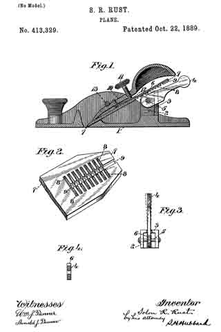
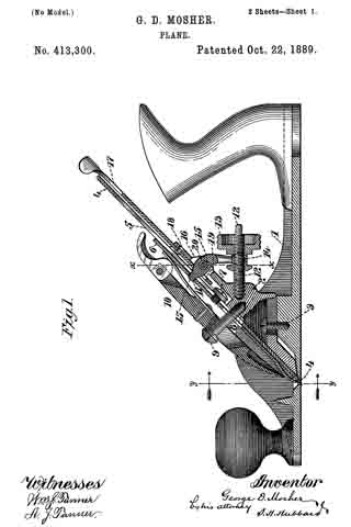
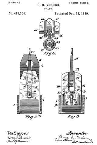
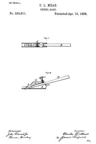
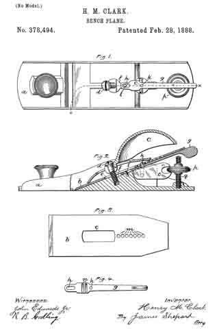
Figure 1, a side view with a portion of the plane-iron broken away to illustrate its connection with the adjusting-lever; Fig. 2, a top view with the plane-iron removed; Fig. 3, a face view of the plane-iron seat with the lever removed to show the transverse slot J and the slide therein.

This invention relates to an improvement in that class of planes in which the stock is made from metal, and in which provision is made for adjusting the upper end of the iron laterally, so as to change the angle of the iron with relation to the working-face of the stock, the invention relating particularly to the mechanism for producing such lateral adjustment; and it consists in the construction as hereinafter described, and particularly recited in the claim.

A represents the stock, which is made from cast-iron, and in which an inclined seat B is formed as a bed for the iron C, D representing the throat of the stock.

E represents the clamp by which the iron is held to its seat, all substantially as in the usual construction, and as here represented it is provided with an adjusting-screw F, by means of which the plane-iron may be raised or lowered to make the out less or more, as the case may be, also in the usual manner.

The particular mechanism as thus far described is too well known to require description.

The upper end of the seat B is recessed, and in the recess a lever G is hung upon a pivot H, and so as to swing in the plane of the seat B, on which the iron rests, this lever G lying directly back of the iron when in place, as seen in Fig. 1. Through the hub or body of this lever a segment-shaped slot I is formed eccentric to the pivot H, and as seen in Fig. Transversely across that portion of the bed in which the lever is hung is a slot J, (see Fig. 3,) in which a slide K is arranged, the said slide presenting a head L on the face adapted to stand in the vertical slot of the plane-iron, the width of the head being substantially the same as the width of the slot.

The said slide extends through the slot I of the lever G, and so that by turning the said lever G to the right or left the slide K will be moved transversely, according to the eccentricity of the slot I, and as indicated in broken lines, Fig. 2, and because the head L of the slide K stands in the slot of the plane-iron it necessarily follows that the upper end of the plane-iron is moved accordingly to the right or left, and such movement of the upper end of the plane-iron correspondingly turns the said iron to change its relation to the face of the plane, and so that the plane-iron may be adjusted to bring the line of its edge parallel with the face of the plane, or inclined thereto, as may be desired. The lever G preferably extends slightly above the upper edge of the plane-iron, so as to form a handle or thumb-piece, as M, by which it may be readily adjusted. When the plane-iron is secured to its seat and it is found necessary to change the line of the cutting-edge of the plane-iron with relation to the face of the plane, it is only necessary to turn the lever G to the right or left, as the adjustment may require, the clamp which secures the plane-iron to its seat being sufficient to hold it in place and yet permit such adjustment to be made, so that the adjustment may be made after the plane-iron has been firmly secured and without change of such securing devices.

From the foregoing it will be understood that I do not claim, broadly, a lever arranged in the stock back of the plane-iron as a means for adjusting the plane-iron transversely; but

What I do claim as my invention is —

In a plane substantially such as described, and in which the plane-iron is secured upon the seat in the stock, the stock constructed with a transverse slot above said seat and in rear of the plane-iron, a lever hung upon the stock in rear of the plane-iron and so as to swing in a plane parallel with the plane-iron and across said transverse slot, the lever constructed with a slot eccentric to the pivot on which it swings, and a, slide working in said transverse slot and extending through the said segmental slot of the lever into engagement with the plane-iron, substantially as and for the purpose described.

In testimony whereof I have signed this specification in the presence of two subscribing witnesses.

GRANVILLE W. WRIGHT.

Witnesses:
E. H. EGGLESTON,
W. S. COOKE.

No. 441,758 – Device For Setting The Edges Of Plane-Bits (Edrick Gowdy) (1890)

[paiddownloads id=”469″]441758


UNITED STATES PATENT OFFICE.

_________________

EDRICK GOWDY, OF ANSONIA, CONNECTICUT.

DEVICE FOR SETTING THE EDGES OF PLANE-BITS.

_________________

SPECIFICATION forming part of Letters Patent No. 441,758, dated December 2, 1890.
Application filed April 10, 1890. Serial No. 347,366. (No model.)

_________________

To all whom it may concern:

Be it known that I, EDRICK GOWDY, a citizen of the United States, residing at Ansonia, in the county of New Haven and State of Connecticut, have invented certain new and useful Improvements in Devices for Setting the Edges of Plane-Bits and other Tools; and I do hereby declare the following to be a f ull, clear, and exact description of the invention, such as will enable others skilled in the art to which it appertains to make and use the same.

My invention has for its object the production of a simple and inexpensive device which may be readily carried about in a tool-box, and which will act to turn forward slightly the edges of plane-bits and other tools. I have found in practice in planing all classes of wood, it being particularly true in the case of knotty close-grained woods, that by turning forward the edge of the bit of the plane I can secure very much better results in the way of a line smooth finish, avoid all danger of chipping out, and can retain the plane-bit sharp and in good condition for use much longer than when the edge is left to project downward in a line with the front of the blade in the usual manner; and in order that I may set the edges of plane-bits without inconvenience and at any time I have devised the simple and novel tool of which the following description, in connection with the accompanying drawings, is a specification, numbers being used to denote the several parts.

Figure 1 is a perspective of my novel tool, showing also a portion of a plane-bit at the angle at which it is passed over the turning-piece; Fig. 2, a longitudinal section of my novel tool, showing the turning-piece in elevation. Fig. 3 is an elevation on a greatly-enlarged scale of the lower end of a plane-bit, showing the edge turned forward as after it has been acted upon by my novel tool; and Fig. 4 is a section similar to Fig. 2, showing a slightly-different mode in which I have carried my invention into effect.

1 denotes a block, preferably made of wood, which is provided with a hole 3, bored into the block from either end near the top of the block and adapted to receive a round piece of metal 4, which I term a “turning-piece.” This turning-piece is preferably made of chilled steel, and is made slightly larger than the hole, so as to require to be driven therein and remain firmly wherever it is placed. It will be noticed that hole 3 is made near enough to the top of the block so that the upper portion of the hole is open. This permits the rounded surface of the turning-piece after it is driven in to project slightly above the surface of the block, as is clearly shown in the drawings. In practice I preferably drive a plug 2 into the hole after the turning-piece has been driven in and smooth it off level with the top and end of the block, so as to give a neat finish to the tool. For convenience in driving the turning-piece out, should it be required, I preferably provide a hole 5, which extends into hole 3 from the other end of the block. Should the turning-piece become worn or nicked in use, it may readily be driven out, given a partial rotation to place another portion of the rounded surface in operative position, and then driven back to place and the plug driven in after it.

In use, after sharpening a plane-bit or other blade, the operator takes the blade firmly in his hand, holding it at about the angle indicated in the drawings, and passes it backward and forward over the turning-piece one or more times, as may be required. The action of the portion of the turning-piece lying above the surface of the block will be to turn the cutting-edge forward slightly, as shown in Fig. 3. In Fig. 4 I have shown the block as provided with a transverse undercut groove 7, the undercut side of said groove being the forward side, which is made perfectly straight, but is inclined downward and inward. The hole to receive the turning-piece is lower down in the block and is intersected by the groove, the rounded surface of the turning-piece lying about the same distance above the bottom of the groove that it does above the surface of the block in the other form. In using this form the operator passes the blade, the edge of which is to be turned through the groove and over the surface of the turning-piece one or more times in the same manner as in using the other form.

In order to hold the block firmly in place and make the tool convenient in use, I provide two or more sharpened prongs 6, which project downward from the bottom of the block to engage a work-bench or plank and hold the block firmly in place when it is desired to use the tool.

Having thus described my invention, I claim —

1. A tool for setting cutting-edges, consisting of a, block having a, rounded turning-piece driven therein, the upper portion of which extends slightly above the surface of the block, so that a, cutting-edge passed over the surface of the block will engage the rounded surface of the turning-piece and be turned slightly forward, as and for the purpose set forth.

2. A tool for setting cutting-edges, consisting of a block having a rounded turning-piece driven therein and extending slightly above the surface thereof, and prongs upon the under side thereof, whereby the block may be held in place in use.

In testimony whereof I afflx my signature in presence of two witnesses.

EDRICK GOWDY.

Witnesses:
CHAS. S. WEEKS,
Mrs. E. GOWDY.

No. 435,951 – Bench-Plane (Arthur E. Rust) (1890)

[paiddownloads id=”466″]435951


UNITED STATES PATENT OFFICE.

_________________

ARTHUR E. RUST, OF PINE MEADOW, CONNECTICUT,
ASSIGNOR OF ONE-HALF TO SOLON R. RUST, OF SAME PLACE.

BENCH-PLANE.

_________________

SPECIFICATION forming part of Letters Patent No. 435,951, dated September 9, 1890.
Application filed July 29, 1889. Serial No. 319,130. (No model.)

_________________

To all whom it may concern:

Be it known that I, ARTHUR E. RUST, a citizen of the United States, residing at Pine Meadow, in the county of Litchfield and State of Connecticut, have invented certain new and useful Improvements in Bench-Planes; and I do hereby declare the following to be a full, clear, and exact description of the invention, such as will enable others skilled in the art to which it appertains to make and use the same.

My invention relates to improvements in bench-planes in which the bit is adjusted by means of a lever; and the objects of my improvement are, first, to provide a means of adjusting the bit of a bench-plane longitudinally, making it cut the thickness desired, and, second, to adjust the bit laterally, thus squaring the cutting-edge of the bit with the face of the plane. Both objects are attained by the movement of one lever either longitudinally or laterally, each motion being independent of the other, as illustrated in the accompanying drawings, in which —

Figure 1 is a side elevation. Fig. 2 is same as Fig. 1, being partially in section. Fig. 3 is a view of the adjusting-lever, showing its bearing on the pin, and is also partially in section.

Similar letters refer to similar parts throughout the several views.

The body of the plane A is similar to that of other planes, and to it is secured a frame B, having an upward extension to receive the screw D and form a bearing or support for the pin F, upon which is pivoted a lever C in such a manner as to allow the lever C to he moved laterally as well as on the pin F as a pivot. Thus the lever C may be given either of two motions upon one bearing or pin F. The lever C is provided with three extensions G, H, and I. The extension I passes through a slot in the bit J and through the hole a in the cap-plate K, as shown in Fig. 2, so that when the screw D is turned or screwed into the threaded hole in the casting B one end of the screw D will bear against the extension H and move the lever C, which will move the cap-plate K and bit J, making the cutting-bit cut a thicker shaving, or if the screw D be turned the other way or unscrewed the lower end of the screw D will bear against the extension G, thus moving the cap-plate K and the bit J up, so that the bit J will cut a thinner shaving. If the cutting-edge of the bit is not square with the face of the plane, it may be made so by moving the lever C laterally in the direction required.

What I claim as new, and desire to secure by Letters Patent, is —

In a bench-plane, the herein-described mechanism for adjusting the cutting-bit longitudinally or laterally, consisting of a lever one end of which (being the upward extension) passes through a slot in the bit and through a hole in the cap-plate, this lever being so made and pivoted in a suitable supporting-frame as to allow the other end or downward extension to be moved in either of two directions upon one pivot or fulcrum to adjust the cutting-bit longitudinally or laterally, substantially as shown and described, for the purpose specified.

In testimony whereof I affix my signature in presence of two witnesses.

ARTHUR E. RUST.

Witnesses:
AMIE S. JEWELL,
FREDERICK A. JEWELL.

No. 423,424 – Bench-Plane (Samuel Frisbie) (1890)

[paiddownloads id=”461″]423424


UNITED STATES PATENT OFFICE.

_________________

SAMUEL FRISBIE, OF UNIONVILLE, ASSIGNOR TO THE
UPSON NUT COMPANY, OF FARMINGTON, CONNECTICUT.

BENCH-PLANE.

_________________

SPECIFICATION forming part of Letters Patent No. 423,424, dated March 18, 1890.
Application filed April 15, 1889. Serial No. 307,352. (No model.)

_________________

To all whom it may concern:

Be it known that I, SAMUEL FRISBIE, a citizen of the United States, residing at Unionville, in the county of Hartford and State of Connecticut, have invented certain new and useful Improvements in Bench-Planes, of which the following is a specification.

My invention relates to improvements in bench-planes; and the objects of my improvement are simplicity in construction and efficiency in operation.

In the accompanying drawings, Figure 1 is a central longitudinal section, partly in elevation, of my plane. Fig. 2 is a sectional view of the same on the line x x of Fig. 1, looking squarely upon the face of the movable bed. Fig. 3 is a central longitudinal section, partly in elevation, of my plane in its preferred form; and Fig. 4 is a transverse section of the stock on line y y of Fig. 3, together with a rear elevation of the remaining parts, the cutting-bit and holding-cap being removed.

A designates the stock, of any ordinary form in its general features, and provided with a short section of a frog or seat 5 for the lower end of the cutting-bit 6, said frog-section having on its rear under side a perforation in which the tenon or projection 7 of the movable cutter-bed 8 is loosely fitted, so that said bed may move longitudinally with the cutting-bit, and also rock laterally at its upper end, the tenon 7 serving as a fulcrum on which it rocks. The rear and upper end of this movable bed rests upon a stud 9, and is held in place thereon by means of the screw 10, which passes through a slot in said bed, so as to permit a certain degree of longitudinal and transverse movement of the bed. This bed is so mounted upon the end of the stud 9 that its upper face is substantially a continuation of the sloping face of the frog-section 5. The holding-cap 11, of ordinary construction, is held in place by the screw 12 for clamping the cutting-bit 6 firmly upon the movable bed 3 substantially as such holding-cap and screw have heretofore held the bit upon a stationary bed. The longitudinal adjustment of the cutting-bit is effected by means of the adjusting-screw 13, which carries the movable bed up and down and the cutting-bit with it.

In the preferred form I form an extension 14 on the upper end of the stud 9, to the rear of which I pivot the laterally-adjusting lever 15, with its handle in a pendent position and with its upper end entering a slot 16 in the upper end of the movable bed, whereby a movement of said lever will adjust the movable bed either to the right or left and carry with said bed the cutting-bit, and thereby effect the well-known lateral adjustment of said cutting-bit.

The modification shown in Figs. 1 and 2 is in effect substantially the same — that is to say, it combines with the movable bed a laterally-adjusting lever for effecting the lateral adjustment of the bit by moving its bed; but instead of having the lever in a pendent position it extends parallel to the cutting-bit, with its major portion underneath said bit.

Instead of pivoting said lever to an extension on the stud 9, it is pivoted to the top of said stud by the same screw 10 that serves to hold the moving bed down upon said stud, and the upper face of said bed is grooved or slotted, as shown at 17, Fig. 2, whereby a lateral movement of the lever 15 will move the bed 8 laterally, as before described, diifering only in the substitution of a lever of a different order.

I claim as my invention —

1. In a plane, the combination of the cutting-bit, the moving bed, devices for clamping said bit upon said moving bed, and a laterally-adjusting lever acting to adjust said bed and bit bodily together in a lateral direction, substantially as described, and for the purpose specified.

2. In a plane, the combination of the cutting-bit, the laterally-moving bed, and devices for clamping said bit to said bed, whereby said bed and bit move together laterally in adjusting the cutting-edge squarely with the stock, substantially as described, and for the purpose specified.

SAMUEL FRISBIE.

Witnesses:
M. C. WOODFORD,
W. E. GRAHAM.

No. 413,329 – Plane (Solon R. Rust) (1889)

[paiddownloads id=”455″]413329


UNITED STATES PATENT OFFICE.

_________________

SOLON R. RUST, OF NEW HARTFORD, ASSIGNOR TO THE BIRMINGHAM
PLANE MANUFACTURING COMPANY, OF BIRMINGHAM, CONNECTICUT.

PLANE.

_________________

SPECIFICATION forming part of Letters Patent No. 413,329, dated October 22, 1889.
Application filed June 25, 1888. Serial No. 315,458. (No model.)

_________________

To all whom it may concern:

Be it known that I, SOLON R. RUST, a citizen of the United States, residing at New Hartford, in the county of Litchfield and State of Connecticut, have invented certain new and useful Improvements in Planes; and I do hereby declare the following to be a full, clear, and exact description of the invention, such as will enable others skilled in the art to which it appertains to make and use the same.

My invention relates to certain new and useful improvements in planes, and has for its object to provide a construction which shall be simple and easy of operation, and whereby a limited adjustment of the cutting-bit relative to the mouth of the plane may be readily effected; and with these ends in view my invention consists in the details of construction and combination of elements hereinafter fully and in detail explained, and then recited in the claims.

In order that those skilled in the art to which my invention appertains may fully understand its construction and operation, I will describe the same in detail, reference being had io the accompanying drawings, which form a part of this specification, and in which —

Figure 1 is a central vertical longitudinal section through a plane constructed in accordance with my invention; Fig. 2, a detail perspective showing the method of grooving the under surface of the plane-bit; Fig. 3, a detail plan view showing the adusting-lever mounted in its fulcrum-block; Fig. 4, a detail vertical section through the forward end of the lever and the opening through which the pivot passes.

Like numerals denote the same parts in all the figures of the drawings.

1 is the plane-stock, having at its rear end a divided post 2, which supports the bit and serves as the frog. At its rear side this post has a pair of inward projections 3, whose edges are somewhat beveled. (See Fig. 3.) Between the parts of the divided post is secured a lever 4, fulcrumed upon a pin or rivet 5 passed through said post. The hole in the lever is slightly larger than the rivet, and is countersunk from either end thereof, (see detail, Fig. 4,) so that the lever may have an easy movement lengthwise of the pin without binding upon the latter. At the top surface of its forward end the lever is provided with a series of teeth 6 — say three or four in number — arranged on an arc struck from the center of the fulcrum-pin.

7 is the bit, which, upon its back and for a portion of its length, is provided with a series of square-edged transverse grooves 8, spaced to correspond with the spacing of the teeth 6 upon the lever. 9 is a square-edged groove cut lengthwise of the back of the bit and centrally intersecting the transverse grooves heretofore referred to at right angles. The depth of this groove is about half that of the transverse groove, so that a sort of rack is left at the bottom of said longitudinal groove, while at the same time square abutments are left at its sides for the purpose presently explained.

10 is the wedge, having a binding-screw 11 and a flat spring 12 at its under side, against which the end of the screw abuts, so that it may not mar the upper surface of the bit when turned downward to secure it. The wedge binds the bit to the post by the ordinary rneans of a transverse rod 13, extended between the sides of the stock, and underneath which the wedge lies.

When the parts are assembled, as shown at Fig. 1, the operation of my invention is as follows: The teeth upon the lever lie in the longitudinal groove and engage with the transverse grooves which form the rack at the bottom of said groove. It will be readily understood that a limited longitudinal movement either forward or backward may be imparted to the bit by raising or lowering the handle end of the lever, the teeth of which actuate the bit by their engagement with the rack. When a lateral adjustment is desired for the purpose of squaring the cutting-edge of the bit with the plane-mouth, said adjustment may be obtained by a lateral movement of the handle end of the lever. When this is done, the sides of the teeth engage with the square abutments at sides of the longitudinal groove, and, as the lever is pivoted loosely on its pin and may move lengthwise thereon, said lever, for the purpose of this sidewise movement, fulcrums between the edges of the inward projections at the rear of the divided post and slides longitudinally upon the pin.

I claim —

1. In a plane, the combination, with the stock and the doubly-fulcrumed lever, of the cutting-bit having at its rear side the transversely-extended grooves and the shallow longitudinal groove intersecting the transverse grooves at right angles, substantially as set forth.

2. In a plane, the combination, with the cutting-bit, the same having the transverse grooves and the longitudinal groove, whereby a bearing is afforded for its actuation longitudinally and laterally, of the lever having thereon the operating-teeth and two fulcrum-points, one for the operation of the bit longitudinally and the other for its adjustment laterally, substantially as specified.

3. In a plane, the combination, with the bit, the same having the transverse and longitudinal grooves in its rear side, of the divided post, upon which said bit rests, the toothed lever loosely pivoted on a pin within said divided post, and adapted, in addition to its movement upon said pin as a center, to have a movement longitudinally thereof, substantially as set forth.

4. In a plane, the combination, with the bit, having at its rear side the transverse grooves and the shallower longitudinal groove intersecting said transverse grooves at right angles, of the divided post having the beveled inward projections at its rear side, the lever provided with operating-teeth and having a countersunk pivot-hole, and the pin secured in said post and passing loosely through the hole in the lever, substantially as specified.

In testimony whereof I affix my signature in the presence of two witnesses.

SOLON R. RUST.

Witnesses:
WM. H. WILLIAMS,
MARGARET G. TORRANCE.

No. 413,300 – Plane (George D. Mosher) (1889)

[paiddownloads id=”454″]413300


UNITED STATES PATENT OFFICE.

_________________

GEORGE D. MOSHER, OF BIRMINGHAM, CONNECTICUT, ASSIGNOR TO
THE BIRMINGHAM PLANE COMPANY, OF SAME PLACE.

PLANE.

_________________

SPECIFICATION forming part of Letters Patent No. 413,300, dated October 22, 1889.
Application filed June 25, 1889. Serial No. 315,506. (No model.)

_________________

To all whom it may concern:

Be it known that I, GEORGE D. MOSHER, a citizen of the United States, residing at Birmingham, in the county of New Haven and State of Connecticut, have invented certain new and useful Improvements in Planes; and I do hereby declare the following to be a full, clear, and exact description of the invention, such as will enable others skilled in the art to which it appertains to make and use the same.

My invention relates to certain new and useful improvements in planes, but more particularly to means for the adjustment of the cutting-bit; and the object of my invention is to furnish a device which shall be simple in construction and cheap to manufacture, and whereby a limited adjustment either longitudinally or laterally may be imparted to the bit; and with these ends in view my invention consists in the details of construction and combination of co-operating elements hereinafter to be fully set set forth, and then recited in the claims, which are hereunto annexed.

In order that those skilled in the art to which my invention appertains may fully understand its construction and method of op-
eration, I will describe the same in detail, reference being had to the accompanying drawings, which form a part of this specification, and in which —

Figure 1 is a central longitudinal section through the operative parts of a plane constructed in accordance with my invention; Fig. 2, a section through the plane-stock at the line y y of Fig.1, looking in the direction of the arrow, the plane-bit being shown in front elevation and the fastening-wedge being removed; Fig. 3, a similar view, but with the wedge and bit both removed; and Fig. 4, a detail section at line x x of Fig. 1, looking toward the rear of the plane.

Like numerals denote the same parts in all the figures of the drawings.

1 is the plane-stock, having therein secured the frog 2 by screws 3 or other means. 4 is the cutting-bit, slotted longitudinally, as seen at 5, and adapted to lie against the inclined forward face of the frog. 6 is the cap-plate, which lies upon the bit and is secured thereto, as by a screw 7, whose head engages the surface of the bit at either side of the slot in the latter. The cap-plate has an opening 8 therein to allow of movement relative to the screw 9, which projects outwardly from the frog and serves in conjunction with the binding-wedge 10 to secure the bit and cap-plate firmly against the frog, as is common to many planes now in use. The cap-plate has also an opening 11, whose purpose will presently appear. At the rear of the frog, and projecting therefrom in substantially a horizontal plane, is a screw 12, upon which runs a nut 13, which is provided with an annular groove let near its forward end.

15 is a lever pivoted on a pin 20 between ears 16 on the frog. It is yoked at its lower end so as to loosely engage the groove in the nut. The pivot-joint is loose so that the lever may be moved lengthwise upon the pivot-pin, for the purpose presently explained. The upper end of the lever passes through the slot of the bit and enters the opening 11 in the cap, to which it is closely adapted.

17 is a lever fulcrumed at 18 to the upper end of the frog, said lever having near its lower end an elongated opening 19, through which the lever 15 passes and in which it may be moved by the screw.

In the adjustment of the bit by means of the instrumentalities hereinbefore described the longitudinal movement is imparted thereto by moving the nut on the screw, whereby the lever is turned upon its fulcrum and the cap and bit are carried along by means of it. The lateral movement of the bit for squaring its edge with the plane mouth is effected by the lever 17, which, being swung upon its fulcrum, will carry the lever 15 along upon the pin on which it is pivoted and thereby, through said lever, move the bit laterally. To avoid lost motion, the end of the lever 15 should conform closely to the opening in the cap-plate, in which case a very nice adjustment of the bit in both directions may be made.

As the bit wears away, the cap-plate can be moved relatively thereto, so that the lever-opening in the cap may be always in proper relative position toward the lever.

I claim —

1. In a plane of the character described, the combination, with the bit and the cap-plate, of the screw-operated lever, whose end engages the cap-plate, and the laterally-adjusting lever engaging and adapted to move the screw-operated lever and therethrough the bit, substantially as set forth.

2. In a plane, the combination the bit and the perforated cap-plate thereon secured, of the yoked and screw-operated lever pivoted to the frog and movable longitudinally of its bearing and the pivoted laterally-adjusting lever arranged around and adapted to actuate the screw-operated lever, substantially as specified.

3. The combination, in a plane, with the stock and the frog of the slotted bit, of the cap-plate having the opening 11, means, as the wedge, for securing the bit and plate to the frog, the lever 15, engaged and operated by the nut 13 and projecting into the opening 11 in the cap-plate, and the laterally-adjusting lever 17, fulcrnlned to the frog and engaging the lever 15, whereby said lever 15 may be moved along its fulcrurn, substantially as specified.

In testimony whereof I affix my signature in presence of two witnesses.

GEORGE D. MOSHER.

Witnesses:
WALTER S. TORRANCE,
EDWIN B. GAGER.

No. 410,710 – Bench-Plane (George Karrmann) (1889)

[paiddownloads id=”453″]410710


UNITED STATES PATENT OFFICE.

_________________

GEORGE KARRMANN, OF UNIONVILLE, ASSIGNOR TO
THE UPSON NUT COMPANY, OF FARMINGTON, CONNECTICUT.

BENCH-PLANE.

_________________

SPECIFICATION forming part of Letters Patent No. 410,710, dated September 10, 1889.
Application filed May 22, 1889. Serial No. 311,692. (No model.)

_________________

To all whom it may concern:

Be it known that I, GEORGE KARRMANN, a citizen of the United States, residing at Unionville, in the county of Hartford and State of Connecticut, have invented certain new and useful Improvements in Bench-Planes, of which the following is a specification.

My invention relates to improvements in bench-planes having a device for the lateral adjustment of the cutting-bit; and the chief object of my invention is to provide a friction-slide and operating devices for moving the cutting-bit by frictional contact only.

In the accompanying drawings, Figure 1 is a longitudinal section, partly in elevation, of a plane which embodies my invention. Fig. 2 is a face view of the upper portion of the frog, to which my lateral adjustment is applied. Fig. 3 is a like view of the same provided with different operating devices; and Fig. 4 is a transverse section of the same, partly in elevation, on the line x x of Fig. 3. Fig. 1 is on a smaller scale than the figures which follow it.

The plane-stock A, cutting-bit B, holding-cap C and its attachments may be of any ordinary construction, and therefore require no special description.

I have herein illustrated a lever 5, which is operated by the screw 6, for adjusting the cutting-bit B longitudinally, in an old and well-known manner, and for which any other mechanism for adjusting the cutting-bit longitudinally may be substituted.

In the upper end of the frog D, immediately under the cutting-bit B, I place a friction-slide 7, which is fitted in a proper groove or recess to slide transversely to said frog D and with its upper face slightly projecting above the upper face of the frog D. In Figs. 1 and 2 I operate this slide to move it transversely to the cutting-bit by means of the laterally-adjusting lever 8, which is pivoted to the frog, as at 9, while its other end is connected with the friction-slide 7 in any suitable manner — as, for instance, by means of the pin 10.

In Figs. 3 and 4 the friction-slide is provided with a downwardly-extending lug 11, having a screw-threaded hole, and mounted in suitable bearings on the under side of the frog is an adjusting-screw 12, the threaded end of which enters the threaded hole in the lug 11. The screw 12 is left free to revolve in its bearings, but held against longitudinal movement therein by means of shoulders in the ordinary manner of mounting similar screws. I have shown two different devices for moving the slide to indicate that other operating devices may be substituted for the lever 8.

By turning the screw or moving the lever or other operating device the slide 7 may be moved longitudinally in its ways or guides, so as to carry it transversely to the length of the cutting-bit. I prefer to roughen the upper surface or a portion of the upper surface of the slide 7 to increase its frictional contact with the cutting-bit. In use with either form the cutting-bit is merely seated in place and clamped in the ordinary manner, with its under face at the upper end resting upon the frictional slide 7 without any connection with said cutting-bit other than frictional contact. By moving said frictional slide with any suitable operating mechanism the upper end of the cutting-bit may be moved laterally in either direction. By thus moving the bit with a frictional slide it is not necessary to make any provision for wear of the cutter or to provide any special devices for connecting it with the slide or to pay any attention to the arrangements of the slot. It may therefore be used with any ordinary cutting-bit, either slotted or not slotted.

I claim as my invention —

In a bench-plane, the frictionslide 7, arranged to move transversely under the upper end of the cutting-bit, and provided with operating mechanism, substantially as described, and for the purpose specified.

GEORGE KARRMANN.

Witnesses:
S. FRISBIE,
W. W. WOODFORD.

No. 402,886 – Bench-Plane (Frank M. Bailey) (1889)

[paiddownloads id=”449″]402886


UNITED STATES PATENT OFFICE.

_________________

FRANK M. BAILEY, OF NEW BRITAIN, CONNECTICUT, ASSIGNOR TO
THE STANLEY RULE AND LEVEL COMPANY, OF SAME PLACE.

BENCH-PLANE.

_________________

SPECIFICATION forming part of Letters Patent No. 402,886, dated May 7, 1889.
Application filed December 11, 1888. Serial No. 293,248. (No model.)

_________________

To all whom it may concern:

Be it known that I, FRANK M. BAILEY, a citizen of the United States, residing at New Britain, in the county of Hartford and State of Connecticut, have invented certain new and useful Improvements in Bench-Planes, of which the following is a specification.

My invention relates to improvements in bench-planes in which the cutting-bit is adjustable laterally; and the objects of my invention are to improve the general efliciency of the lateral adjustment, and also to effect said adjustment through the cap-screw.

In the accompanying drawings, Figure 1 is a central longitudinal section, partly in elevation, of my plane. Fig. 2 is a transverse section thereof on the line x x of Fig. 1, and Fig. 3 is a like view showing a modification.

A designates the plane-stock, provided with the ordinary cutting-bit, B,its cap-iron C, holding-cap D, longitudinally-adjusting lever E, and its operating-nut F, all of ordinary construction.

The bed for the cutting-bit, or, as it is more generally termed, the “frog,” 4, is cut away through its middle portion to a point a little below the screw 5, by which the holding-cap is held, in order to make room for the laterally-adjusting compound lever composed of the lower member, 6, and upper member, 7, both of which are pivoted to the frog 4 on axes perpendicular to its face, the upper member by means of the pivot 8 and the lower member by means of the screw 5. The lower end of the upper member, 7, is rounded and engages a correspondingly-shaped notch at the upper end of the lower member, whereby a movement laterally of the upper member on its pivot will also move laterally the lower member, thereby enabling the lateral adjustment to be worked with ease and a very fine adjustment to be effected.

In the preferred form I provide the lower member, 6, of the compound lever, with an opening, 9, which will receive and nearly fit the head 10 of the ordinary cap-screw for holding the cap-iron C on the cutting-bit B, whereby a lateral movement of the lever, by thus engaging the cap-screw, necessitates a lateral movement of the cap-iron and cutting-bit. As the cutting-bit wears away at its lower end it will be slipped down farther on the cap-iron; but the cap-screw will always remain at nearly the same distance from the lower end of the cutting-bit, so that the laterally-adjusting mechanism always operates upon the cutting-bit at practically the same distance from its lower end.

In Fig. 3 I have shown the same construction, with the exception that I make the opening in the lower member, 6, of the compound lever large enough not to engage the cap-screw, and I provide said lower member with an upward projection, 12, which is adapted to engage the side walls of the ordinary longitudinal slot in the cutting-bit; or in the absence of said slot said upward projection may enter a hole in the cutting-bit specially adapted to receive it. This alternative form or modification may also be used in planes in which the cap-iron and cap-screw are absent.

I claim as my invention —

1. The combination of the plane-stock provided with the frog 4, the cutting-bit, andthe laterally-adjusting compound lever consisting of the lower and upper members pivoted on axes perpendicular to the face of said frog, substantially as described, and for the purpose specified.

2. The combination of the plane-stock provided with the frog 4, the compound lever consisting of the lower member, 6, having the opening 9 and upper member, 7, both pivoted to said frog, the cutting-bit B, cap-iron C, and the cap-screw 10, the head of which screw rests within the opening 9 of said lower member of the compound lever, substantially as described, and for the purpose specified.

FRANK M. BAILEY.

Witnesses:
H. S. WALTER,
H. C. HINE.

No. 401,532 – Bench-Plane (Frank M. Bailey) (1889)

[paiddownloads id=”448″]401532


UNITED STATES PATENT OFFICE.

_________________

FRANK M. BAILEY, OF NEW BRITAIN, CONNECTICUT, ASSIGNOR TO
THE STANLEY RULE AND LEVEL COMPANY, OF SAME PLACE.

BENCH-PLANE.

_________________

SPECIFICATION forming part of Letters Patent No. 401,532, dated April 16, 1889.
Application filed December 3, 1888. Serial No. 292,540. (No model.)

_________________

To all whom it may concern:

Be it known that I, FRANK M. BAILEY, a citizen of the United States, residing at New Britain, in the county of Hartford and State of Connecticut, have invented certain new and useful Improvements in Bench-Planes, of which the following is a specification.

My invention relates to improvements in bench-planes of the class in which the upper end of the plane-iron is adjusted laterally;
and the object of my improvement is to provide a laterally-adjusting lever which does not necessitate the employnient of a longitudinal slot in the cutting-bit.

In the accompanying drawings, Figure 1 is vertical section of a plane-stock with a side elevation of the other parts of the plane. Fig. 2 is a sectional view of said plane-stock on the line x x of Fig. 1, with a face view of the parts below said line. Fig. 3 is a like view of a portion of a plane-stock and a modified form of laterally-adjusting lever. Fig. 4 is a like view showing still another form of laterally-adjusting lever, the plane of section being on the line y y of Fig. 5; and Fig. 5 is a side elevation of a complete plane, parts of which are illustrated in Fig. 4.

A designates the plane-stock provided with a cutting-bit, B, the same being held in position on its frog by means of the holding-screw 6, holding-cap C, and cam 7. In the form shown in Figs. 1, 2, and 3 the longitudinal adjusting-lever 8 is provided with teeth 9 at its forward end on its upper face, and is moved on its axis by the adjusting-nut 10, which travels up and down upon a screw-threaded post, 11. The central portion of the cutting-bit B, with this form of longitudinally-adjusting mechanism, is provided with a longitudinal series of transverse slots, into which the teeth 9 of the lever 8 engage for adjusting the cutting-bit longitudinally, all as in a well-known prior plane.

Upon the plane-stock underneath the cutting-bit, I pivot the laterally-adjusting lever 12, which lever is provided with laterally-extending arms 13 13, at the outer ends of each of which there is an upwardly-projecting lug, 14, for engagement with the two outer edges of the cutting-bit B. in Figs. 1 and 2 this lever is pivoted to the stock in a central position at a point below the teeth 9 of the longitudinally-adjusting lever, and the central portion of the lever 12 at this point is out away or provided with an opening, through which the engaging end of the lever 8 may project. The laterally-extending arms 13 and upwardly-projecting lugs 14 are formed integral with the lever 12. In the form shown in Fig. 3 these arms and lugs are formed of a separate piece from the lever 12, arranged to slide laterally, and are secured to said lever by the pin 15, so that the lateral movement of the lever 12 carries with it the upwardly-projecting lugs 14. In Figs. 4 and 5 the arms 13 and upwardly-projectings lugs 14 are also formed integral with the lever 13; but the pivot for said lever is located above said arm and lugs. The longitudinally-adjusting mechanism in this latter construction consists of an angle-lever, 16, and adjusting-screw 17, the upper end of the lever 16 taking into the cap-iron 18 of the cutting-bit, all as in a well-known prior construction.

In all of the various forms shown the two outer edges of the cutting-bit are received in between the upwardly-projecting lugs 14 14, so as to be engaged thereby, and the lever is pivoted to the stock underneath the cutter and vibrates laterally in a plane which is parallel to that of the cutting-bit. A lateral movement of the lever on its fulcrum causes the upwardly-projecting lugs to move laterally with said lever. One or the other of the upwardly-projecting lugs 14 (according to which direction the lever is moved) will engage with one edge of the cutting-bit and carry said bit laterally to adjust its lower edge, so as to be square with the stock, the general effect being the same as in lateral adjustments heretofore employed.

I do not claim, broadly, a lever pivoted to the stock underneath and parallel with the cutting-bit for rnoving it laterally; but, so far as I know, these laterally-adjusting levers, when directly engaging the cutting-bit, have been made to engage the cuting-bit at a point midway between its two edges.

I claim as my invention —

In a benoh-plane, the combination of the cutting-bit, a laterally-adjusting lever, the laterally-projecting arms and upwardly-projecting lugs moving laterally with said lever and adapted to engage the outer edges of the cutting-bit, substantially as described, and for the purpose specified.

FRANK M. BAILEY.

Witnesses:
H. S. WALTER,
F. N. STANLEY.

No. 386,509 – Bench-Plane (Justus A. Traut) (1888)

[paiddownloads id=”440″]386509


UNITED STATES PATENT OFFICE.

_________________

JUSTUS A. TRAUT, OF NEW BRITAIN, CONNECTICUT, ASSIGNOR TO
THE STANLEY RULE AND LEVEL COMPANY, OF SAME PLACE.

BENCH-PLANE.

_________________

SPECIFICATION forming part of Letters Patent No. 386,509, dated July 24, 1888.
Application filed April 17, 1888. Serial No. 270,273. (No model.)

_________________

To all whom it may concern:

Be it known that I, JUSTUS A. TRAUT, a citizen of the United States, residing at New Britain, in the county of Hartford and State of Connecticut, have invented a certain new and useful Improvement in Bench-Planes, which improvement is fully set forth and described in the following specification.

Reference is also made to the sheet of drawings annexed hereto, in which Figure 1 is a side elevation of a plane having my improvement embodied therein. Fig. 2 is a sectional detail view of the same on line x x of Fig. 1, and Fig. 3 is a like view with the cutting-bit attached. Fig. 4 is a sectional detailed view on a central longitudinal line. Fig. 5 is a detached perspective view of the lever by means of which the cutting-bit is rocked or adjusted laterally, as hereinafter explained.

The class of planes to which my invention relates is that in which the cutting-bit may be adjusted laterally relative to its seat for the purpose of bringing the cutting-edge of said bit parallel with the throat, or, in other words, square with the plane-stock. A familiar type of said class is shown and fully described in my Patents No. 306,877 issued October 21, 1884, and No. 376,455, January 17, 1888, to which patents reference is hereby made.

The object of my present invention is to improve the construction of the lever employed to adjust the bit laterally, so that said device may work easier and with less friction than heretofore. To produce this desired result I have secured to the bit-engaging end of the adj usting-lever an anti-frictional disk that partially rotates on its axial pivot, as I will proceed to describe.

The letter B denotes the cutting-bit; A, the seat provided for said bit in the so-called “frog” of the plane, and C the cap-iron.

a indicates my new form of lever provided to adjust the bit in a lateral direction. Said lever is perforated, as at a’, to slip over a pin, a2, near the rear end of the bit-seat A, said pin forming the fulcrum on which the lever swings. The bit-seat is recessed, as atb, to receive said lever, said recess being of such depth that the lever may move freely between the bit and frog when the several parts are assembled for use. The lower or short arm of lever a has pivoted to its bit-engaging side a disk, c, that may rotate freely on its pivot. This disk, when the parts are assembled, projects upward into the bit slot d. (See Figs. 3 and 4.)

When it is desired to adjust the bit to square it with the plane-stock, the free end of lever a is swung to one side — as, for example, in Fig. 3 — which action moves the short arm of said lever in the opposite direction, and the disk c carries with or before it the bit B. During this adjusting operation disk c partially revolves on its axial pivot, and so reduces in a considerable degree the friction of the engaging parts.

My device, as described, may be applied to planes of this class without any material changes, and does not add to the cost of such tools.

I claim as my invention —

In combination with the stock and bit of a plane, a lever for laterally adjusting said bit, and the rotary disk pivoted on the shorter arm of said lever and engaging the longitudinal slot of said bit, substantially as described, and for the purpose specified.

JUSTUS A. TRAUT.

Witnesses:
HENRY S. WALTER,
H. C. HINE.

No. 380,811 – Chisel-Gage (Charles L. Mead) (1888)

[paiddownloads id=”433″]380811


UNITED STATES PATENT OFFICE.

_________________

CHARLES L. MEAD, OF NEW YORK, N. Y., ASSIGNOR TO
THE STANLEY RULE AND LEVEL COMPANY, OF NEW BRITAIN, CONNECTICUT.

CHISEL-GAGE.

_________________

SPECIFICATION forming part of Letters Patent No. 380,811, dated April 10, 1888.
Application filed January 26, 1888. Serial No. 261,982. (No model.)

_________________

To all whom it may concern:

Be it known that I, CHARLES L, MEAD, a citizen of the United States, residing at New York, in the county of New York and State of New York, have invented certain new and useful Improvements in Chisel-Gages, of which the following is a specification.

My invention relates to improvements in chisel-gages for use in blind-nailing, and the main object of my improvement is to prevent the shaving turned up from breaking off.

In the accompanying drawings, Figure 1 is a plan view of my gage with a portion of a chisel to which the gage is attached, and Fig. 2 is a central longitudinal section of said gage with a side elevation of said portion of a chisel.

In blind-nailing a narrow shaving is raised up from the surface of the wood, a nail or brad then driven into the wood at the place from which the shaving was raised, and then the shaving is glued and turned back to cover the nail-head. My gage is designed for attachment to a chisel for such use.

I prefer to form the body A of sheet metal from a flat blank bent up at each side into a trough-shaped body, as shown. The bottom of this trough-shaped body is the gaging-surface, and is provided with a throat, through which the cutting-edge of the chisel-blade B may project and on the rear edge of which it may rest, as shown. The chisel-blade also rests upon the cross pin a.

Immediately above and forward of the rear edge of the throat there is a rearwardly and upwardly inclined guard, b, the same being nearly or quite parallel to the front face ofthe chisel-blade at its forward end. As illustrated, this guard is turned up from the bottom face of said sheet-metal body, the metal being merely slit at the end and sides of the guard to enable it to be thus turned up. While I prefer to thus form the body and guard of sheet metal, it is evident that the same form of body and guard might be made of cast metal.

The gage is held in place on the chisel-blade by the clamping mechanism, which consists of the pivoted clamping-lever C and its screw c.

The guard b prevents the shaving from rolling up as it is raised from the wood; in other words, it is not bent on as short a curve as it would be without said guard, and consequently it is less liable to be broken off before or when putting it back into place for covering the nail-heads.

I claim as my invention–

1. The herein-described gage for chisels, the same consisting of the body, the clamping mechanism for attaching it to a chisel-blade, and a guard immediately above and forward of the rear edge of the throat in th under side of said body and extending rearwardly and upwardly, substantially as described, and for the purpose specified.

2. The herein-described gage for chisels, the same consisting of the body and clamping mechanism for attaching the gage to a chisel-blade, said body being formed of sheet metal and having the guard b bent upwardly from the bottom face of said sheet-metal body, substantially as described, and for the purpose specified.

CHARLES L. MEAD.

Witnesses:
H. S. WALTER,
JAMES SHEPARD.

No. 378,854 – Grooving And Boxing Tool For Carriage-Makers (Justus A. Traut) (1888)

[paiddownloads id=”430″]378854


UNITED STATES PATENT OFFICE.

_________________

JUSTUS A. TRAUT, OF NEW BRITAIN, CONNECTICUT, ASSIGNOR TO
THE STANLEY RULE AND LEVEL COMPANY, OF SAME PLACE.

GROOVING AND BOXING TOOL FOR CARRIAGE-MAKERS.

_________________

SPECIFICATION forming part of Letters Patent No. 378,854, dated February 28, 1888.
Application filed July 6, 1886. Serial No. 207212. (No model.)

_________________

To all whom it may concern:

Be it known that I, JUSTUS A. TRAUT, a citizen of the United States, residing at New Britain, in the county of Hartford and State of Connecticut, have invented certain new and useful Improvements in Grooving and Boxing Tools for Carriage-Makers, of which the following is a specification.

My invention relates to improvements in carriage-makers’ tools of the class usually termed “rooters;” and one object of my invention is to increase the utility and efficiency of the tool, so that it may do the work of several separate tools as heretofore constructed.
In the accompanying drawings, Figure 1 is a plan view of my tool in the form adapted to do the work of one style of rooter. Fig. 2 is a front elevation of the same, together with a piece of work. Fig. 3 is a reverse plan view of said tool. Fig. 4 is a front elevation of the same tool differently adjusted, so as to perform the work of another style of rooter, said figure also showing a piece of work. Fig. 5 is a side elevation of one side of one of the ears to which the handles are attached. Fig. 6 is a like view of that face of the handle which confronts the face of the handle-ears, Fig. 5. Fig. 6a is a transverse section on line y y, Fig. 1, of the stock of my tool, showing the other parts in side elevation. Fig. 7 is a reverse plan view of the middle portion of my tool, corresponding to Fig. 3, but with shoes or guides added thereto. Fig. 8 is a view showing the back side of the cutter for the rooter. Fig. 9 is a reverse plan view of my tool arranged for use as a boxer or paneling-tool. Fig. 10 is a front elevation of the same. Fig. 11 is a transverse section of the same on line x x of Fig. 10, and Fig. 12 is a like section of the same with the cutting-tool reversed.

A designates the stock of my implement, which stock is substantially a flat block with smooth under side and edges, having an upwardly-projecting tool-post, a, and handle-ears b b. For convenience of holding the handles B B in the desired positions, a rib, c, Fig. 5, is formed on the face of the handle-ears b b, and as many grooves, d, Fig. 6, are formed on the face of the handle-shank as may be desired, into either of which grooves the rib may enter to hold the handles in the desired position. The screw e serves as a pivot on which the handles turn after-the screw has been loosened sufficiently to let the rib c disengage the grooves. The screw alone might be depended upon to hold the handles in place; but by the use of the rib c and grooves there is less liability of displacement from any given adjustment. These screws e are substantially parallel with a transverse line across the under face of the stock, to enable the handles to be set for use in the relation to the under face of the stock shown in Figs. 1, 2, and 3, or as in Fig. 4. For most uses the handles will beset parallel with the stock A, as in Figs. 1, 2, 3, 9, and 10.

Side guides or gages, C C, are secured upon the stock A, the same being fitted to slide thereon and to be fastened in place, when adjusted, by means of the set-screws f. The stock A has an opening by the side of the tool-post a, through which the shank of the T-shaped tool D passes, said tool being held in position by the yoke E and its clamp-screw g. The two ends of the cross member of the T-shaped tool D are made hooked, as shown most clearlyin Figs. 3 and 7, to form, respectively, right and left hand cutters, either of which may be used. The shank of the tool is grooved longitudinally and fits a vertical rib on the side of the tool-post a. The gages G C can be set to have the ends of the cutters project a distance equal to the desired depth of cut.

F, Fig. 2, designates a piece of work such as the rooter is designed to groove, the implement being shown in said figure in position for forming said groove, the under face of the stock gaging the distance of the groove from the top of the work, while the gage C will gage the depth of cut. In starting a groove with the rooter, the cutter may be prevented from taking too rank a cut by canting the position of the tool with reference to the work, letting one handle fall backward and the other forward, so that the forward corner of one of the gages C may come against the work. As the groove deepens, the operator will give the tool a less canting position to feed the cutter in as fast as may be desired, until finally that part of the gage near the cutter bears on the work and the tool can cut no deeper without changing the gage.

If desired, shoes or guards k k may be secured to the under side of the gages C C just in front of the cutter, as shown in Fig. 7, so as to prevent the cutter from working too rank; but when the tool is used as above described these shoes are not essential.

In Fig. 4, G designates a piece of work of a different form, and in order to adapt the tool for this work the handles are adjusted into a position at right angles to the stock, so that the implement may be applied to the work as illustrated and then conveniently operated by the handles.

In Figs. 9, 10, 11, and 12 the implement is arranged for use as a boxer or paneling-tool. The T-shaped tool D and depth-gages C C are removed and the tool H substituted for the tool D. Like tools of varying widths are furnished, either of which may be used. This tool thus arranged may be used for sinking a box or panel or for smoothing the surface thereof. It will ordinarily be used as arranged in Figs. 9, 10, and 11; but sometimes for working in cramped places it may be desirable to secure the tool upon the other side of the tool-post a and reverse the position of the yoke E, as shown in Fig. 12.

I claim as my invention —

1. The combination of the stock A, having handles B B, the T-shaped cutter D, having a cutting-edge at each end of its cross member, whereby right or left hand cuts may be made without special adjustment, mechanism for holding said cutter, and the gages C C, substantially as described, and for the purpose specified.

2. The combination of the stock, right and left gages and cutters adapted for use in cutting lateral grooves either on the right or left side of vertical faces, and the handles B B, pivoted on axes which are substantially parallel with a transverse line across the under face of the stock and adapted to be adjusted and secured at different angles to the stock, substantially as described, and for the purpose specified.

3. The herein-described convertible rooter and boxer, consisting of the stock A, having a flat under face, the rooting and boxing cutters fltted for separate application to the stock, clamping mechanism for holding either of said cutters with their cutting end projecting below the bottom face of the stock, and attachable and detachable transverse gages for attachment to the bottom face of the stock, substantially as described, and for the purpose specified.

JUSTUS A. TRAUT.

Witnesses:
JOHN EDWARD, Jr.,
JAMES SHEPARD.

No. 378,494 – Bench-Plane (Henry M. Clark) (1888)

No. 378,494 – Bench-Plane (Henry M. Clark) (1888)

[paiddownloads id=”428″]378494


UNITED STATES PATENT OFFICE.

_________________

HENRY M. CLARK, OF NEW BRITAIN, CONNECTICUT, ASSIGNOR TO
THE STANLEY RULE AND LEVEL COMPANY, OF SAME PLACE.

BENCH-PLANE.

_________________

SPECIFICATION forming part of Letters Patent No. 378,494, dated February 28, 1888.
Application filed July 23, 1887. Serial No. 245,046. (No model.)

_________________

To all whom it may concern:

Be it known that I, HENRY M. CLARK, a citizen of the United States, residing at New Britain, in the county of Hartford and State of Connecticut, have invented certain new and useful Improvements in Bench-Planes, of which the following is a specification.

This invention relates to improvements in the bit-adjusting mechanism of bench-planes; and the object of the improvement is to simplify the construction and to allow the several parts to be cheaply made and quickly assembled with but little fitting.

In the accompanying drawings, Figure 1 is a plan view of the stock or body of a plane of my new construction with cutting-bit and holding-cap removed. Fig. 2 is a vertical section of said plane on line x x of Fig. 1. Fig. 3 is a plan of the cutting-bit, and Fig. 4 an under side view of the lever by means of which said bit is moved laterally to square its cutting-edge with the stock.

The arrangement of the devices by means of which I effect both a lateral and longitudinal adjustment of the bit is believed to be new and forms an essential feature of my invention. Heretofore, so far as I know, the mechanism for adjusting the bit longitudinally has been connected directly with the cutting-bit or its cap-iron. In my improvement the lever for lateral adjustment forms the means of connecting the bit with the longitudinal adjustment, and thereby constitutes an essential part of said longitudinal adjustment.

In the drawings, a indicates the stock of the plane; b, the cutting-bit; c, the holding-cap, and d the screw provided for locking the cap and bit in their respective positions, the parts thus far named being old and well known. The solid portion,or so-called “frog,” of the stock a is inclined on its upper face at a proper angle to produce a shaving cut of the bit b, which bit rests on said frog at its lower end, and is slotted, as at e, to allow said bit to move both laterally and lengthwise without engaging the cap-screw d. That portion of the frog which is designed to receive the lever g is cut down, as at f, so that when the parts are assembled said lever lies underneath the bit with its upper surface in line with the forward part of the frog. The inner end of said lever is provided with a slot, h, which straddles a pin, i, projecting from the frog, said slot and pin forming a floating fulcrum for said lever. Between said fulcrum and the free end of lever g is a pivot-pin, k, projecting upward from said lever, and adapted to enter any one of a series of holes, m, in bit b.

Assuming, now, that we have a plane of the construction thus far described, the lateral movement of lever g in either direction will move the cutting-bit b (in the same direction) a distance proportionate to the leverage provided. In order to add to said construction mechanism for moving the bit longitudinally to govern the depth of the cut, I have provided transverse recesses or grooves n in the under side of lever g, and have connected therewith a toothed plate, o, pivoted in the stock a, and actuated by a thumb-nut, p, on a fixed screw, q. This device in itself is well known and needs no detailed description, and other known mechanism for longitudinal adjustment may be substituted therefor. It will now be understood that when it is desired to increase the depth of out the turning of thumb-nut p to the left hand will elevate the forked end of the plate o, and thus move forward lever g and the cutting-bit, to which said lever is attached by pin k.

Lever g is allowed to move lengthwise a considerable distance by the fulcrum-slot h, and as the bit becomes worn and shortened pin k may be entered in the next hole, m, of the series. To adjust bit b laterally to square its cutting-edge with stock a, the free end of lever g is swung to one side, as above noted, the action being the same as in planes of this class now in common use. When said lever is thus moved laterally, the recesses or grooves n, being of considerable length, remain in engagement with the teeth of plate o, so that the bit may be adjusted longitudinally without adjusting it laterally, or vice versa.

I am aware that a prior patent for a bench-plane shows and describes an adjusting-screw connected to and operating a longitudinally-sliding block that is clamped to the under side of the cutting-bit by a screw which passes through a fellow plate on the upper side of the cutting-bit and through the slot in said bit, which block, fellow plate, and screw form the sole means of connecting the adjusting-screw with the cutting-bit. The said sliding block and fellow plate have connected thereto a laterally-adjusting lever, the same being carried longitudinally with said block and fellow plate. Such a plane, having a laterally-adjusting lever which merely rides upon the mechanism for adjusting the cutting-bit longitudinally without forming an essential part of said longitudinal adjusting mechanism, is hereby disclaimed.

I claim as my invention —

1. In a bench-plane, the combination of the laterally-adjusting lever, the mechanism for operating directly upon said lever for adjusting it longitudinally, and the cutting-bit connected to said laterally-adjusting lever, whereby said lever forms an essential part of the mechanism for adjusting the cutting-bit longitudinally, substantially as described, and for the purpose specified.

2. In a bench-plane, the combination of the cutting-bit having a series of holes, m, the laterally-adjusting lever let into the face of the frog and fulcrumed thereon by a pin-and-slot connection, said lever also having a pin for insertion in one of the holes m, and mechanism applied directly to said lever for adjusting it, and through it the bit in a longitudinal direction, substantially as described, and for the purpose specified.

HENRY M. CLARK.

Witnesses:
JOHN EDWARDS, Jr.,
JAMES SHEPARD.

No. 377,645 – Bench-Plane (John H. Shaw) (1888)

[paiddownloads id=”427″]377645


UNITED STATES PATENT OFFICE.

_________________

JOHN H. SHAW, OF NEW HAVEN, CONNECTICUT, ASSIGNOR TO
SARGENT & COMPANY, OF SAME PLACE.

BENCH-PLANE.

_________________

SPECIFICATION forming part of Letters Patent No. 377,645, dated February 7, 1888.
Application filed July 5, 1887. Serial No. 243,353. (No model.)

_________________

To all whom it may concern:

Be it known that I, JOHN H. SHAW, of New Haven, in the county of New Haven and State of Connecticut, have invented a new Improvement in Planes; and I do hereby declare the following, when taken in connection with accompanying drawings and the letters of reference marked thereon, to be a full, clear, and exact description of the same, and which said drawings constitute part of this specification, and represent, in —

Figure 1, a side view of the plane complete; Fig. 2, a face view of the plane-iron bed, showing the transverse adjusting-screw; Fig. 3, a back side view of the plane-iron; Fig. 4, a vertical section through the transverse adjusting-screw and in the slot of the plane-iron; Fig. 5, a modification in the support of the transverse adjusting-screw.

This invention relates to an improvement in that class of planes in which the stock is made from metal, and is provided with means for adjusting the plane-iron to give a greater or less cut. Usually the only adjustment made by the mechanism of the plane itself is to produce a greater or less extent of cut by the plane-iron; but in setting the plane-iron a lateral adjustment is necessary. This is generally produced by means of a hammer striking the edge of the plane-iron to turn it to the right or left, as the case may be, to bring it into proper relation to the face of the plane. A device has been applied to the plane by which the lateral adjustment may be produced mechanically, this device consisting of a lever hung upon the stock and engaged with the iron, so that by turning the lever to one side or the other the plane-iron will be thrown accordingly; but this adjustment is liable to displacement by accidental blows upon the lever, and is not capable of that nice adjustment which is necessary in setting the iron, and is inconvenient in many respects. In another case an endless screw has been transversely arranged across the stock of the plane, and in engagement with the same lever by which the cut of the plane is adjusted; but in this construction the adjustment by one screw is liable to be deranged by the adjustment of the other screw, because of both screws acting in different directions upon the same lever.

The object of my invention is to apply a screw for the transverse adjustment of the iron, but independent of the cut-adjusting device, whereby the nicest adjustment may be produced without liability of accidental displacement.

A represents the stock, which may be any of the usual or known constructions, and in which the plane-iron B is arranged in the usual manner and secured by any suitable device.

C represents the adjusting-screw by which the plane-iron is adjusted to produce a greater or less cut — a common and well-known device, and does not require particular description. The stock is provided with a solid bed, D, upon which the plane-iron rests, also in the usual manner. In the stock, above the point where the adjusting device engages the plane-iron, (E representing the opening in the bed through which the adjusting device engages the iron,) I arrange a transverse screw, F, there being a transverse recess, G, formed across the bed for this purpose. In the recess in the bed one or more bearings, a, are formed for the screw, the seats in these bearings being of less diameter than the body of the screw. The screw itself is constructed with annular grooves b, corresponding to the bearings a, and so that laid into the bearings, as indicated in Fig. 2, the screw may rotate in the bearings, but held by the bearings against movement in an axial direction.

The outer end of the screw is provided with a suitable head, H, by which it may be turned. On the screw is a nut, I, adapted to slide through the recess in which the screw is applied, the nut being internally screw-threaded corresponding to the thread of the screw, and because the nut can not revolve in the recess, owing to its shape, as seen in Fig. 4, it follows that the rotation of the screw will impart to the nut a transverse movement, according to the direction in which the screw is turned. The nut projects above the face or bearing-surface of the bed and enters the slot J in the plane-iron B, the length of the nut corresponding to the width of the slot, the slot being of a standard width in all irons adapted to a certain size plane.

When the plane-iron is secured in the stock in the usual manner, if it be desired to impart transverse movement to the iron in either direction, the screw H is turned accordingly, and through the nut I imparts such required transverse movement to the plane-iron, and when once set there is no liability of accidental dis-adjustment, and the most perfect adjustment may be made by the screw, much more so than can be produced by a lever which is turned by hand or by blows imparted to it.

The bearings a in the recess in the bed are equidistant from the center, so that the screw may be introduced with its head either to the right or left, as indicated in Fig. 2, solid lines indicating the left-hand position and broken lines the right-hand position. The bearings are simply of U shape, open outward, as seen in Fig.2, so that the screw may be dropped therein. The adjusting device is therefore readily removable from the plane should occasion require.

It will be understood that the transverse adjustment may be applied to a plane with any of the many different vertical adjustments, or without vertical adjustment should it be desired.

While I prefer to construct the recess with the bearings a, into which the screw may be dropped or readily removed, as I have described, it may be supported permanently in the recess, as seen in Fig. 5, it only being essential that when the screw is in its place it shall be prevented from movement in an axial direction, yet left free for rotation, and carry the nut.

From the foregoing it will be understood that I do not claim, broadly, the combination, in a plane, of a transverse or lateral adjusting-screw for the plane-iron.

I claim —

In a plane substantially such as described, the bed upon which the plane-iron rests, constructed with a transverse recess, G, and with one or more bearings, a, therein, combined with a screw, F, constructed with annular groove or grooves corresponding to said bearing or bearings and adapted to set therein, the said screw provided with a head upon its outer end, by which it may be rotated, a nut, I, in said recess and upon said screw, but independent of the cut-adjusting mechanism, the said nut adapted to engage the plane-iron, substantially as and for the purpose described.

JOHN H. SHAW.

Witnesses:
OTTO SCHLIEPER,
CHAS. L. BALDWIN.

No. 376,455 – Bench-Plane (Justus A. Traut) (1888)

[paiddownloads id=”426″]376455


UNITED STATES PATENT OFFICE.

_________________

JUSTUS A. TRAUT, OF NEW BRITAIN, CONNECTICUT, ASSIGNOR TO
THE STANLEY RULE AND LEVEL COMPANY, OF SAME PLACE.

BENCH-PLANE.

_________________

SPECIFICATION forming part of Letters Patent No. 376,455, dated January 17, 1888.
Application filed July 23, 1887. Serial No. 245,062. (No model.)

_________________

To all whom it may concern:

Be it known that I, JUSTUS A. TRAUT, a citizen of the United States, and a resident of New Britain, in the county of Hartford and State of Connecticut, have invented certain new and useful Improvements in Bench-Planes, which improvements are so described in detail in the following specification as to enable others skilled in the art to which they pertain to make and use the same, reference being also had to the annexed sheet of drawings, in which —

Figure 1 is a plan view of a plane-stock with bit-adjusting devices attached thereto, the position of the bit being indicated in dotted lines. Fig. 2 is a side elevation of a plane, with a portion of the stock (on line x x, Fig. 1) in section to expose the operative parts of the tool.

These improvements are applicable to bench-planes in which provision is made for both lateral and longitudinal adjustment ofthe cutting-bit, a familiar type of said planes being shown in my former patent, No. 306,877, of October 11, 1884. In said former patent I have experienced some inconvenience in pivoting the lever which provides lateral adjustment of the bit, and also in combining in a practical manner said lever with certain forms of mechanism for providing longitudinal adjustment.

My present improvements are intended to overcome these defects and to utilize in the best possible manner the limited space devoted to these mechanisms.

Referring to the drawings, the letter a indicates a plane-stock, b the notched plate by which longitudinal adjustment of the bit c is attained, d the thumb-nut which actuates said plate, and e the screw which holds the cap-section k in place, said section being brought into bearing on said bit by means of the cam f which is pivoted thereto, all of these parts being old in this class of planes.

Immediately below the bit c is located a lever, g, whose inner end is perforated and preferably tapped to fit the threaded portion of screw e. This screw is thus made to serve as the fulcrum of said lever, and simplifies in a considerable degree the construction of the plane. When tapped out, as above stated, the fit should be loose enough so there will be no tendency to turn and loosen screw e as the lever is swung from side to side. By threading the hole in the lever and pivoting it on the threaded portion of the screw, the lever is always held in proper position on the frog, so that it will not become displaced when the cap-section is removed. Said lever is formed with an integral upwardly-projecting rib, h, which enters a slot in bit c (shown in dotted lines in Fig. 1) and acts to move said bit substantially the same as the lever in my said former patent, with this exception, that in the present instance the manner of pivoting forms a lever of the second order instead of the first, as before. Lever g, as it leaves the fulcrum-screw, is bent laterally and extends rearward at one side of the notched plate b, and is then preferably brought back into the same vertical plane as the pivoted end first described. (See Fig. 1.) This laterally-bent form of adjusting-lever allows me to enlarge, strengthen, and alter the mechanism provided for longitudinal adjustment of the bit, and to adopt other means of longitudinal adjustment which would lie in the path of straight levers as now commonly used.

Having described my improvements, I claim as new and wish to secure by Letters Patent —

1. In combination with the stock and cutting-bit of a bench-plane, a lever for laterally adjusting said bit, fulcrumed on the screw which secures the cap section, in substantially the manner and for the purpose herein specified.

2. In combination with the stock and bit of a plane, a lever for laterally adjusting said bit, said lever being tapped to fit and fulcrumed on the cap-screw, substantially as and for the objects specified.

JUSTUS A. TRAUT.

Witnesses:
H. S. WALTER,
F. N. STANLEY.

No. 355,031 – Bench-Plane (Samuel D. Sargent) (1886)

[paiddownloads id=”418″]355031


UNITED STATES PATENT OFFICE.

_________________

SAMUEL D. SARGENT, OF NEW BRITAIN, CONNECTICUT, ASSIGNOR TO
THE STANLEY RULE AND LEVEL COMPANY, OF SAME PLACE.

BENCH-PLANE.

_________________

SPECIFICATION forming part of Letters Patent No. 355,031, dated December 28, 1886.
Application filed September 6, 1886. Serial No. 212,803. (No model.)

_________________

To all whom it may concern:

Be it known that I, SAMUEL D. SARGENT, a citizen oi the United States, residing at New Britain, in the county of Hartford and State of Connecticut, have invented certain new and useful Improvements in Bench-Planes, of which the following is a specification.

My invention relates to improvements in bench-planes, and has particular relation to the manner of holding the cutting-bit within the stock.

One object of my improvement is to produce a plane in which the bit can be clamped by fewer and more direct motions, and therefore more conveniently, than heretofore.

In the accompanying drawings, Figure 1 is a plan view of my plane. Fig. 2 is a side view of the same, partly in section and partly in elevation. Fig. 3 is a like view with the holding-cap placed in position with its lever raised ready for clamping the bit. Fig. 4. is a plan view of my holding-cap and its lever detached from the plane, and Fig. 5 is a like view of the reverse side of the same.

The stock A and the means for adjusting the cutting-bit after it is clamped within said stock may be of any ordinary construction.

B designates a headed screw set in a threaded hole in the frog or stock in the ordinary manner of this class of planes, so that by screwing it in or out the distance between the under side of the screw-head and the upper side of the cutting-bit C may be adjusted. A fixed stud with an adjustable head or a headed bolt adjusted by a nut would be the equivalent of this screw.

D is the holding cap or wedge, having a hole near its center, as viewed in plan view, which hole is large enough to let the head of the screw B pass through it. Pivoted to this cap by means of the pintle a is the clamping-lever E, the upper end of which is preferably of a form which will serve as a handle for the plane, while its lower and short end is slotted to take under the head of the screw upon two sides. The slot in this lever opens into the central hole in the cap. Said slot also extends both forward and backward of the pintle a, and hence said pintle is in two parts — one on each side of said slot — as indicated by the broken lines in Fig. 5.

The holding-cap is so formed on its under side as to bear upon the cutter only at the ends of said cap. After setting the bit in place the holding-cap and attached lever are placed on the bit (or on the cap-iron in case of a double plane-iron) by letting the central hole pass over the screw-head, then slipping the holding-cap downward to let the slotted end of the lever under the head of the screw, as shown in Fig. 3. The long end of the lever E is then depressed, when said lever fulcrums on the under side of the screw-head and carries the holding-cap downward into the position shown in Fig. 2, in which the pintle a (indicated by the broken circle) is slightly in advance of the lever on the screw-head, and consequently the pressure on the screw will hold the lever in its clamping position. If the adjusting-screw is properly set, the bit will be then firmly clamped. In putting in the clamping device the operator takes hold of the handle only and sets the holding-cap in place, then merely presses the outer end of the handle obliquely downward with only one motion. It will thus be seen that in clamping the bit the movement of the cap and lever-handle is practically in the same direction — forward and downward — and therefore these parts are more conveniently handled than parts which require to be moved in reverse directions — as, for instance, when the lever requires to be first moved backward and upward, as is the case in several prior planes. The clamping mechanism is also believed to be very efficient.

I claim as my invention —

In a plane, the combination of the holding-screw B, the holding-cap D, adapted to bear at each end upon the bit, and the clamping-lever pivoted or hinged to said cap between the bearing ends and having its upper face adapted to engage and fulcrum upon the under side of the screw-head, substantially as described, and for the purpose specified.

SAMUEL D. SARGENT.

Witnesses:
F. N. STANLEY,
W. J. WORAM.

No. 352,056 – Beading-Tool (Oscar E. Hildebrand) (1886)

[paiddownloads id=”417″]352056


UNITED STATES PATENT OFFICE.

_________________

OSCAR E. HILDEBRAND, OF NORWICH, CONNECTICUT.

BEADING-TOOL.

_________________

SPECIFICATION forming part of Letters Patent No. 352,056, dated November 2, 1886.
Application filed July 15, 1886. Serial No. 208,051. (No model.)

_________________

To all whom it may concern:

Be it known that I, OSCAR, E. HILDEBRAND, a citizen of the United States, residing at Norwich, in the county of New London and State of Connecticut, have invented certain new and useful Improvements in Beading-Tools, which improvements are fully set forth and described in the following specification, reference being had to the accompanying drawings, in which —

Figure 1 is a side view of said improved tool, and Fig. 2 a top view of the same. In Fig. 3 I have shown a transverse sectional view on line x x of Fig. 2.

My improvements are in that class of tools used commonly by cabinet makers and other wood-workers for grooving, channeling, or beading work, which cannot easily be done by machinery; and my object is to provide a practical tool, which shall be serviceable and strong, yet cheap.

My device is preferably constructed entirely of metal, the several pieces being of such shape I that they may be assembled with but little fitting.

Referring to the drawings, the letters a a’ represent rods, which are semicircular in cross-section and of sufficient length to receive at each end a handle, b, which handle I prefer to make of cast-iron. These handles are cored centrally throughout their length to slip over the two rods a a’, as will be understood by referring to Fig. 3, and are shaped at the irinner ends with flanges c c, which form gages to guide and control the movement of the knife when in use.

My cutting-tool proper is punched or otherwise formed from steel, and a single blank may have, if desired, several cutters of different designs on its opposite edges, as shown at d in Fig. 1. The cutter thus formed is entered between the flat sides of rods a a’, and the handles b are then adjusted to form the bead at the desired distance from the edge of the board, the depth of the cut being determined by the distance which the cutter projects below the rods. In order to clamp the parts thus adjusted firmly together, I have drilled and tapped the handles to receive clamping-screws e e, which, when screwed home, clamp the parts as rigidly as if they were integral with each other.

By forming my entire tool of metal, I find that the weight thus gained gives an impetus to the tool, which is desirable rather than objectionable, inasmuch as it requires less effort on the part of the operator. In many cases the thumb-screws e e may be dispensed with, the handles being forced onto rods a a’, which action squeezes the rods together sufficiently to hold the cutter; but as a rule I prefer to use clamping-screws, as shown.

Having described my invention, I claim —

1. In a beading-tool, in combination with two companion rods, a cutter adapted to be clamped between said rods, as described, and handles cored to slip over said rods to clamp the said cutters, all being substantially as herein specified.

2. In combination with two semicircular rods, a cutter adapted to be clamped between said rods, and handles cored to slip over said rods, as described, said handles being provided with clamping-screws, by which the several elements may be clamped together, for the purpose specified.

3. In combination with two companion rods, a cutter adapted to be clamped between said rods, as described, handles cored to slip over the ends of said rods and formed with gage-flanges at their inner ends, and thumb-screws or similar means for clamping the several parts together, substantially as herein set forth, and for the purpose specified.

OSCAR E. HILDEBRAND.

Witnesses:
FRANK H. ALLEN,
TYLER J. HOWARD.

No. 350,613 – Bench-Plane (Frank M. Bailey) (1886)

[paiddownloads id=”415″]350613


UNITED STATES PATENT OFFICE.

_________________

FRANK M. BAILEY, OF NEW BRITAIN, CONNECTICUT, ASSIGNOR TO
THE STANLEY RULE AND LEVEL COMPANY, OF SAME PLACE.

BENCH-PLANE.

_________________

SPECIFICATION forming part of Letters Patent No. 350,613, dated October 12, 1886.
Application filed March 23, 1885. Serial No. 196,285. (No model.)

_________________

To all whom it may concern:

Be it known that I, FRANK M. BAILEY, a citizen of the United States, residing at New Britain, in the county of Hartford and State of Connecticut, have invented certain new and useful Improvements in Bench-Planes, of which the following is a specification.

My invention relates to improvements in bench-planes, and has particular reference to mechanism for adjusting the cutter.

The object of my invention is to provide a simple, convenient, and inexpensive mechanism for this purpose.

In the accompanying drawings, Figure 1 is a perspective view of a bench-plane showing my adjusting mechanism, and Fig. 2 is in part a longitudinal section through the adjusting mechanism and in part an elevation.

The plane in its general feature is of ordinary construction, of which a designates the cutting-bit-, b the cap-iron, and A the holding cap or clamp for holding the cutter in place. I pivot an angle-lever, c, in the body of the holding cap A, with one arm of said lever projecting through the holding-cap into a hole made to receive it in the cap-iron b in case of a plane having a double iron, or in the cutter itself or some part rigidly affixed thereto in case of a plane having a single iron. The outer end of the lever, as shown, has two arms, d d, which constitute the operating-handles for moving the lever to adjust the cutter up or down. These two handles are a convenience, as by pressing upon one of them the cutter is forced downward, while pressing upon the other forces the cutter upward. Only one arm, however, is necessary, as that will operate to adjust the cutter both ways by pulling outward or depressing said arm.

The main feature of my invention resides in the adjusting-lever pivoted to the holding-cap, and having a handle which forms a part of said lever upon the upper front side of said holding-cap.

I am aware that it is old to employ a lever having one arm connected with the cutter, while the other arm serves as an operating-handle of a plane-bit-adjusting mechanism, said lever being pivoted to the stock underneath and back of the cutting-bit, and the same is hereby disclaimed. Such an adjusting-lever can only be reached by the ends of one’s fingers, and is very inconvenient to operate, besides being in the way when grasping the handle of the plane. By my invention all the space under the frog and in front of the handle is left open and unobstructed, so that there is plenty of room for the fingers of the operator while grasping the handle, and no liability of hitting and hurting the fingers, as there is in planes having this space cramped by an adjusting mechanism. The construction is also very much simplified, so that the plane can be produced at a small cost. It also enables me to use a T form of lever when desired, so that the cutter can be adjusted both up and down by covering the two arms d d with the palm of one’s hand and bearing down upon either arm. Such a mode of adjusting cannot be employed when the adjusting-lever is placed back of and underneath the cutting-bit. Even with only one arm for an operating-handle, the lever is much more accessible and more conveniently operated than in any prior plane known to me.

I am also aware that an adjusting mechanism for a plane iron is shown in a prior patent as provided with an operating-screw for the adjusting mechanism, the handle of which screw is upon the upper front side of the holding cap or clamp, and I hereby disclaim the same.

I claim as my invention —

1. In a bench plane, the combination of the cutting-bit a, the holding cap or clamp A, and the adjusting-lever pivoted thereto and having its operating-handle on the upper front side of said holding cap or clamp, substantially as described, and for the purpose specified.

2. In a bench-plane, the adjusting angle-lever c, having one arm for connecting with the cutting-bit projected through the holding cap or clamp A and pivoted thereto, and the two arms d d, extending in opposite directions from the main arm upon the upper front side of the cap, to serve as operating-handles, substantially as described, and for the purpose specified.

FRANK M. BAILEY.

Witnesses:
H. S. WALTER,
CHAS. B. STANLEY.

No. 348,198 – Variable Bench-Plane (Amos Fales) (1886)

[paiddownloads id=”413″]348198


UNITED STATES PATENT OFFICE.

_________________

AMOS FALES, OF ROCKFALL, CONNECTICUT.

VARIABLE BENCH-PLANE.

_________________

SPECIFICATION forming part of Letters Patent No. 348,198, dated August 31, 1886.
Application filed July 29, 1885. Serial No. 172,960. (Model.)

_________________

To all whom it may concern:

Be it known that I, AMOS FALES, residing in Rockfall, in the county of Middlesex and State of Connecticut, have invented Improvements in Variable Bench-Planes; and I do hereby declare that the following is a full and exact description thereof, reference being had to the accompanying drawings, making part of this specification.

Figure 1 is a view in perspective of the main stock of the instrument as provided with my improved means of applying the fillister and grooving attachments with reversible and adjustable fence; Fig. 2, a front end view of the same; Fig. 3, a side view of one of the attaching-brackets; Fig. 4, a top view of the same; Fig. 5, a front end view of the instrument having its fence reversed for making a front fillister; Fig. 6, a front view of a set of dado-spurs of different sizes; Fig. 7, a side view of one of the spurs; Fig. 8, a side view of the main stock, with a pair of form-plates attached thereto, showing the manner in which the dado-spurs are applied; Fig. 9, a bottom view of the same; Fig. 10, a front view of a spur having only one cutting-point; Fig. 11, a side view of the main stock provided with thin removable extension-flanges for cutting extremely-narrow grooves; Fig. 12, a bottom view of the same; Fig. 13, a front end view of the same; Fig. 14, a side view of the front form-plate constructed to be adjustable lengthwise; Fig. 15, aside view of a special form of cutter used; Fig. 16, an end view of the same; Fig. 17, a top view of a cutter provided with a cap-iron attached thereto; Fig. 18, a side edge view of the same; Fig. 19, a bottom view of the same; Fig. 20, a front view of forward form-plate having a dado-spur.

Like letters designate corresponding parts in all of the figures.

The general construction of the bench-plane on which the present improvements are based is shown and described in the previous patents granted to me March 7, 1882, and April 1, 1884, and numbered, respectively, 254,542 and 295,916. Especially I will refer to one or the other of those patents for the construction of the main stock A, with its flange a, for attaching other parts of the instrument thereto, and means for securing the cutters B therein, the front and back form-plates, C D, and the reversible fence E.

Referring to those former patents, it will be noted that the front and back form-plates are attached to the downwardly-projecting stock-flange a, each by means of a single set-screw, b, fitting in a vertical notch or slot, c, of the form-plate flange d.

The first improvement herein to be described consists in the means whereby grooving and filiister attachments are applied, as shown in Figs. 1, 2, 3, 4, and 5. Two brackets, G G, are employed, constructed substantially as shown — that is, each with a vertical flange, e, having a vertical notch or slot, f, whereby it is attached to the flange a of the stock by one of the set-screws b b, used for attaching the form-plates, which are dispensed with for the special purposes of this device, and each having a horizontal flange, g, with a notch or slot, h, at right angles to the stock-flange, for attaching the reversible fence E by screws i i. The upper edges or terminations, e e e, of each bracket are in one horizontal line, in order to fit against the overhanging ledge k of the stock and serve as a guide or gage for placing the bracket in a correct position without care. Thus this entire appendage is attached to the main stock by the same means as the form-plates used for other kinds of work. Fig. 2 shows how the fence thus attached by these brackets is used for grooving.

Fig. 5 shows the fence reversed and provided with an overhanging ledge, l, for forming a front fillister. Here the ledge, being in line with the lower edge of the stock-flange a, serves for form-plates, which, for this purpose, therefore, are dispensed with. The ledge l is cut away in the middle, so not as to be in the way of the cutter, and not to interfere with the discharge of the shavings. The fence being adjustable laterally allows the grooves to be cut at any desired distance from the front edge of the material, and by employing two stocks — one arranged for grooving and the other for tonguing — no changing from one to the other kind of work is necessary for tonguing and grooving. The vertical flange of each bracket is of such height that when placed in contact with the overhanging ledge k of the main stock the grooves will be cut to the regular or greatest depth required, the distance from the lower surface of the bracket to the lower edge of the stock-flange determining the depth of cut, since the brackets serve as gages to limit the depth of cut. When a shallower cut is desired, the brackets may be adjusted farther down on the stock-flange, both brackets alike, thus obviously effecting the purpose.

Fig. 6 of the drawings shows a front view of a set of dado-spurs of different widths, and Fig. 7 a side view of either one of the spurs. Each spur H is a double spur, having two cutting-points, m m, cutting at both edges of the work cut by the cutter used, whether for dado, fillister, bead, or other form of cutting. Between the cutting-points m m is a space, n, of sufficient depth to admit the form cut, of whatever shape. Each spur has a vertical (preferably round) stem, o, which is inserted in a vertical hole in the plane-stock. Each spur, in combination with a cutter and main-stock flange, is a complete dado. The stem o of each spur is always at the same distance from one extremity and spur, whatever the distance of the other spur from the first spur, so that the various widths of spurs always bear the same relative and proper position on the stock, and all the spurs are attached by the same means.

The means of attaching each spur is shown in Figs. 8 and 9. The round stem o of the spur is inserted in a vertical hole through the main stock; A and its flange a, and the body p of the spur has parallel faces or front and back sides, which fit against the sides of a notch, q, in one of the form-plates, which lap over the lower edge of the stock-flange, so that the spur is readily adjusted up and down, and yet is held iirmly and accurately in position without turning out of line. The spur is retained in place by a set-screw, r, screwed into the side of the stock. The same general construction and means of attaching the spur apply when it only has one cutting-point, as shown in Fig. 10, and at the right hand in Fig. 6. The spurs are located in advance of the side and center cutters, as shown in Figs. 8 and 9, the front form-plate, C, being notched to receive the spur used a little in advance of the position of the cutter in the main stock, substantially as shown. By this construction cross-grained and curly wood is smoothly cut, the spur-point leading the cutter-edges of the cutter.

Another improvement in my present invention consists in the means by which extremely narrow grooves may be cut with the instrument. Since the main-stock flange is required to be three-sixteenths of an inch thick, or thereabout, in order to give it suflicient strength with this alone, no groove less than three-sixteenths of an inch wide can be cut therewith. For the purpose of cutting narrower grooves, which are often required or very desirable, I employ extension-flanges I J, front and back, as shown in Figs. 11, 12, and 13. These flanges are made of steel and as thin as required. They extend below the main-stock flange a sufficiently to cut the requisite depth below the same, as shown in Fig. 13. Each extension-flange is secured to the front side of the main-stock flange and reaches up to the overhanging ledge k of the main stock, and is attached to the flange by a single set-screw, b, the same as for attaching the form-plates when used. Thus no change in or addition to the usual construction of the plane is required, except as to the extension-flanges themselves, which are cheaply made. A correspondiugly-narrow dado-spur, H, is combined with the front extension-flange, as shown in Figs. 11 and 12. This spur is held in a shallow vertical groove in the front side of the flange, and held there by a set-screw, s. The spur is slotted vertically where held by the screw for the purpose of adjustment. A similar way of attaching a spur to the front form-plate is shown in Fig. 20, the spur being reversible and cutting-edges different. By the above construction a groove not exceeding one-sixteenth of an inch in width may be readily cut, and a double-point spur used to make smooth sides, and a series of narrow grooves from that width up to three-sixteenths is easily made by using spurs and cutters of the various widths required. These extension-flanges can be used with the grooving and fillister attachments above described, or with the auxiliary stocks described in my former patents above mentioned.

Another point of improvement consists in the adjustable mouth for the cutter, so that a wide mouth may be had, when required, or a narrow mouth for cutting the finest shaving without any liability of the front form-plate coming in contact with the edge of the cutter. The mouth is made adjustable simply by means of the front form-plate, C, being made with its attaching notch or slot widened where the attaching-screw passes through it, as shown at t in Figs. 8 and 14. This widening is but little, since the entire adjustment required is quite limited in extent. The head of the attaching-screw will cover the sides of the notch or slot in any position of its adjustment. There is a V-shaped groove, u, or of a form conforming to the shape of the cutter itself, in the front side of the cutter, as shown, forming thereby overhanging cutting-edges v v on both sides of the groove. By this construction the edges overcut, instead of undercutting in the wood, as does the ordinary cutter, so that there is no tendency to raise or tear up the fibers of the wood. With this improved construction of the cutter cross-grained wood may be grooved, and any wood grooved across the grain as smoothly as when the cutter cuts with the grain of the wood. The construction of this cutter will be made the subject-matter of a design patent, it being represented in this application in order to show its mode of application. The cap-iron K is shown as short, only covering a little of the lower end of the cutter B, so that the main part of the cutter is not incumbered therewith, and its body fits in the stock with the cap-iron, the same as if the cap-iron were not there, one form of stock, therefore, serving for such cutters as well as for all other forms of cutters used. The cap-iron is attached by a set-screw, w, passing through a slot, x, in the cutter, as shown in Fig. 19. Thereby the cap-iron is made adjustable to the edge of the cutter. This cap-iron may be applied to dado, flllister, hollow, and round cutters.

I disclaim in this invention form plates or extensions attached to the main flange, such as set forth in Letters Patent No. 295,916, granted to me April 1, 1884, wherein such extensions project at right angles to the main-stock flange, and do not and cannot extend below the said stock-flange.

I claim as my invention —

1. The combination of the stock A, the fence E, and the brackets G G, the said brackets being provided with vertical and vertically-slotted flanges e e, whereby they are adjustably attached to the stock, and with horizontal flanges g g, having slots at right angles to the stock, whereby the fence is attached in position adjustable toward and from the stock, substantially as and for the purpose herein specified.

2. In combination with the stock A and its main attaching-flange a, the vertical plane extension-flanges I J, attached to the side of the main flange, and extending directly downward therefrom and below the same, whereby very narrow grooves may be cut in the material, less in width than the thickness of the said main flange, substantially as herein set forth.

3. The combination of the stock A, having a main attaching-flange, a, a front vertical plane extension-flange, I, removably attached to the said main flange, extending directly downward from and below the lower edge of the said main flange, and provided with a double spur, H, and the rear vertical plane extension-flange, J, removably attached to the main flange and extending directly downward from and below the lower edge thereof, substantially as and for the purpose herein specified.

4. The combination of the stock A, having a flange, a, and front form-plate, G, having an attaching-slot, c, widened from front to back, whereby the said form-plate may be adjusted forward or backward by the attaching-screw b, substantially as and for the purpose herein specified.

AMOS FALES.

Witnesses:
LYMAN A. MILLS,
ERNEST F. COLES.

No. 342,235 – Plane (Justus A. Traut) (1886)

[paiddownloads id=”410″]342235


UNITED STATES PATENT OFFICE.

_________________

JUSTUS A. TRAUT, OF NEW BRITAIN, CONNECTICUT, ASSIGNOR TO
THE STANLEY RULE AND LEVEL COMPANY, OF SAME PLACE.

PLANE.

_________________

SPECIFICATION forming part of Letters Patent No. 342,235, dated May 18, 1886.
Application filed February 23, 1886. Serial No. 192,752. (No model.)

_________________

To all whom it may concern:

Be it known that I, JUSTUS A. TRAUT, a citizen of the United States, residing at New Britain, in the county of Hartford and State of Connecticut, have invented certain new and useful Improvements in Carpenters’ Plows, of which the following is a specification.

My invention relates to improvements in carpenters’ plows, and the object of my invention is to make a convertible “bull-nose”
and common plow so that said plow may be used for plowing a groove up to a shoulder — as, for instance, in grooving window-sash — or so that the plow may be used for the ordinary purposes.

In the accompanying drawings, Figure 1 is an elevation of my plow, showing the rear side. Fig. 2 is a side elevation thereof, showing the front end. Fig. 3 is a plan view thereof. Fig. 4 is an enlarged view of a portion of my said plow. Fig. 5 is a vertical section, partly in elevation on the line x x of Fig. 3, of a part of said plow enlarged. Figs. 6 and 7 are side elevations enlarged of interchangeable tongues for the front end of the stock of my plow; and Fig. 8 is an edge view of a portion of a window-sash, showing a groove such as my plow is adapted to make when used as a bull-nose plow.

A designates the main portion of the stock; B B, the gage-rods secured thereto; and C the gage supported by said rods, all of which in their main features are of ordinary construction.

The main portion of the tongue or blade a, which is back of the cutter b and projects downward from the stock A, is secured there to in any ordinary manner. The portion of the tongue or blade which is forward of the cutter I form of two interchangeable tongues, a’ and a2, either of which in ay be attached to the stock. I make these interchangeable tongues attachable and detachable, so that one may be inserted for the other when desired, in the following manner: The under edge of the stock upon one side is provided with a vertical groove which cuts through the longitudinal groove in the bottom edge of the stock. This longitudinal groove is of a width which is designed to receive the upper edge of the interchangeable tongues a’ and a2, while the width of the vertical groove is such as to receive the tenon c, that projects from the upper edge of the interchangeable tongues a’ and a2. This tenon is provided with a threaded hole, which is adapted to receive the threaded shank at the end of the gage-rods, the hole through the stock A for the front gage-rod being bored smooth and large enough to admit said shank, as shown in Fig. 5. Thus it will be seen that slipping either one of the interchangeable tongues into place and screwing up the gagesrod firmly will hold said convertible tongue in proper position to form a continuation of that portion of the tongue or blade a which is in rear of the cutter, and that by unscrewing said gage-rod one convertible tongue may be removed for the insertion of the other. The ordinary depth-gage, D, is fitted to the vertical groove in the front end of the steel; A, and rests against the side of the tenon c. It is held-in position by means of the nut d.

When the plow is to be used for ordinary purposes, where there is plenty of room, the longer one, a2, of the interchangeable blades is attached to the stock; but when designed to be used in cramped places, so as to cut into a small hole or closely to a shoulder, the shorter one, a’, of the interchangeable tongues is attached, thereby converting the plow into what is termed a “bull-nose.” An example of such use is illustrated in Fig. 8, which shows the edge of a window-sash and the groove for the cord. In such work a hole, e, is bored in the sash and then the groove f is plowed out, the groove terminating within the hole. The length of the tongue a’ is less than the diameter of the hole, and consequently the whole of the groove f may be cut with the bull-nose plow. This cannot be done by a plow of the ordinary construction. In one sense of the word both portions of the blade or tongue of the stock have been made attachable and detachable. They are ordinarily formed of a separate piece from the body of the stock and set in a groove in the lower edge thereof, and held in position by rivets or screws; but, so far as I am aware, no one has ever heretofore provided a plow with interchangeable long and short tongues for attachment and detachment forward of the cutter for the purpose of making a convertble bull-nose and ordlnary plow.

I claim as my invention —

The herein-described convertible bull-nose and ordinary plow, the same provided with interchangeable longer and shorter tongues for attachment to the forward part of the stock, substantially as described, and for the purpose specified.

JUSTUS A. TRAUT.

Witnesses:
H. S. WALTER,
F. N. STANLEY.