No. 291,178 – Plane (William B. Fenn) (1884)
UNITED STATES PATENT OFFICE.
_________________
WILLIAM B. FENN, OF MERIDEN, CONNECTICUT, ASSIGNOR TO FOSTER, MERRIAM & CO., OF SAME PLACE.
PLANE.
_________________
SPECIFICATION forming part of Letters Patent No. 291,178, dated January 1, 1884.
Application filed September 3, 1883. (No model.)
_________________
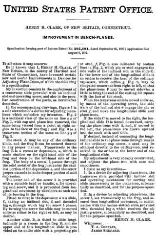
To all whom it may concern:
Be it known that I, WILLIAM B. FENN, of Meriden, in the county of New Haven and State of Connecticut, a citizen of the United States, have invented a certain new and useful Improvement in Planes, of which the following is a full, clear, and exact description, reference being had to the accompanying drawings, forming a part of this specification, in explaining its nature, in which —
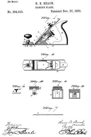
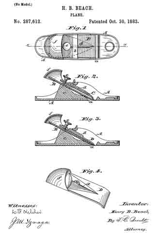
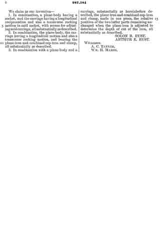
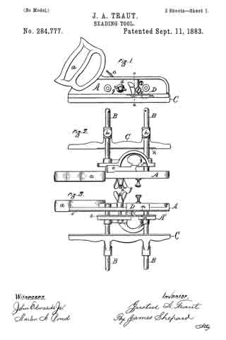
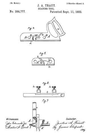
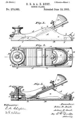
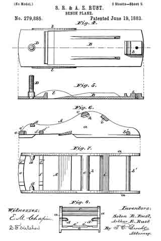
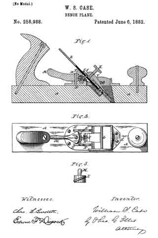
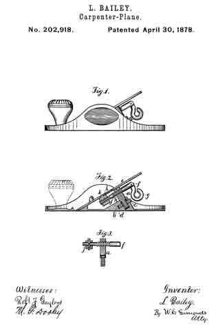
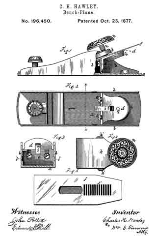
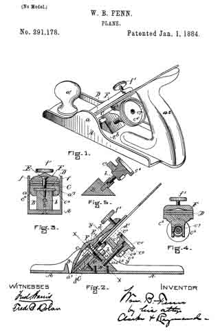
Figure 1 is a perspective view of a plane containing my invention. Fig. 2 is a longitudinal vertical section. Fig. 3 is a cross-section on the line x x of Fig. 2. Fig. 4 is a vertical section on the line y y of Fig. 2. Fig. 5 represents a modification in construction hereinafter described.
The invention relates to various details of construction, all of which are hereinafter fully described.
Referring to the drawings, A represents the stock of the plane. It is made of metal, has the vertical side extensions or flanges, a, the handles a1 a2, and the knife-opening a3. Cast with the stock, or secured thereto by rivets or in any other desirable way, is the triangular-shaped block B. This block is narrower than the plane-stock, and is arranged immediately back of the knife-opening, and there is a recess or space between its vertical sides and the inner sides of the extension or flange a. Its upper surface is inclined, preferably, parallel with the incline a5 of the knife-opening. To this upper surface of the block is fastened by screws a6, or otherwise secured, a plate, a7, which is of the same inclination as the surface of the block, and which extends beyond it on each side to furnish supports or ways for the carriage C, which holds the plane iron or knife.
Instead of making the plate a7 separate and attaching it to the block B, it may be made integral therewith, if desired. The location of this block and plate in relation to the knife-opening and to the side flanges, a, of the plane is well shown in Fig. 3.
Extending upwardly and backwardly from the block B is the threaded spindle or screw, b, by which, in connection with the devices hereinafter described, the carriage, and there-fore the plane irons or knives, is adjusted vertically.
The carriage C has the flat upper surface or bed c, upon which the plane irons or knives D rest, the flat under portion, c1, which slides upon the upper surface ef the plate a7, and the outwardly-projecting portions or wings c2, which extend under the under surface of the side edges of the plate a7, and secure the carriage thereto in a manner to permit it to be moved vertically thereon without being raised or lifted therefrom — that is, these are formed in the downwardly-projecting portions of the carriage grooves or recesses which fit the outer edges of the plate a7. It is of course immaterial as to how these grooves or recesses are formed. They may be made in casting the block, or they may be planed out; and it is also immaterial as to their shape and the shape of the edges of the plate in cross-section, as this shape may be square, or partially rounded, or inclined upon the under edge. The carriage C also has the downwardly-extending lug or bracket c3, which has the projections c4, that straddle the portion c5 of the nut c6. This nut has a thread, c7, which fits the thread on the inclined screw or spindle b. The shoulders c8 c9, at the lower end of the nut, fasten the projections c4 of the carriage securely to the nut, so that upon the revolution of the nut the carriage is raised or lowered.
It will be observed that the nut is so located in relation to the back handle of the plane that it can be easily revolved without removing the hand from the handle, so that the plane irons or knives may be adjusted while the plane is being moved. The plane-irons are secured to this block; by means of the headed screw-spindle E, which screws into the carriage, and of course may be adjusted in and out in relation thereto, and which passes through the hole e in the plane-irons and the key F, which has formed in its under surface in any desirable way the projections f, which shut under the head cf the screw. The under surface, and especially the lower edge of the key, bears upon the upper plane-iron, and the screw f1 in its upper end bears upon the upper plane-iron, throws the lower portion of the key rigidly against the lower portion of the plane-iron, and being held to the carriage by the headed spindle or screw E, the plane knives or irons are rigidly fastened to the carriage. The plane-irons are secured to each other by the coupling-screw d, and a hole, d1, is made in the carriage to receive the head of this screw.
The advantages of this invention are simplicity and cheapness of construction and ease of adjustment of the irons.
It will be observed that the threaded spindle or stem b need not necessarily be secured to the block B, as it can be fastened to any other part of the stock or body of the plane, provided it is arranged to project diagonally upward, as shown.
It will also be seen that by making the headed screw E adjustable in the carriage plane-irons of varying thickness may be used, and that a tight fit between the key-piece, plane-irons, and carriage may be obtained, which is desirable, as it prevents chips, dust, and shavings from getting between the various parts, and also holds the plane-irons more securely in place.
In Fig. 5 I show the nut secured by the body of the plane or block B, instead of to the knife-carriage C; and I prefer to secure the nut in place by tapping a hole in the block or body of the plane and forming a projection on the end of the nut, which shall tightly fit the hole when driven therein. The screw-spindle will, in this construction, take the place of the nut c6 in relation to the carriage C, and the screw will enter the stationary nut; or, in other words, in this modification the nut is stationary and the screw-spindle movable with the carriage.
Of course the invention can be used in planes having wooden bodies, or bodies having wooden bottoms and metal frames, if desired.
Having thus fully described my invention, I claim and desire to secure by Letters Patent of the United States —
1. A plane bed or stock having the block B, cast upon or fastened to the inside thereof, of less width than the body of the plane,and provided with ways or guides for the support of a movable plane knife or iron supporting carriage formed thereon by means of the projections a7, all substantially as and for the purposes described.
2. The combination of the plane bed or stop A, the block B, fastened or secured thereto, narrower than the plane-stock, and having the projecting guides a7, with a movable or knife-supporting carriage, G, having the outwardly-projecting portions or wings c2, which lap under the under surface of the guides, all substantially as and for the purposes described.
3. The combination, in a plane, of the stock or bed A, the block B, fastened thereto as described, and of less width than the body of the plane, provided with the ways or guides a7, which project therefrom, as specified, the threaded spindle or screw b, the plane knife or iron supporting carriage C, having the projecting portions c2, which lap upon the under surface of the guides or fianges a7, and the nut c5, secured to said carriage, as described, all substantially as and for the purposes set forth.
4. The combination, in a plane, of the threaded spindle or stem fixed in the body of the plane, the plane iron or knife supporting carriage C, having the projections c4, which straddle the nut c5, the said nut c6, which works upon the threaded stem, all substantially as and for the purposes described.
5. The plane knife or iron supporting carriage C, having the bracket or projection c3, whose projecting ends straddle the grooved or recessed nut c6 between the shoulders c8 c9. all substantially as and for the purposes described.
6. The combination of the adjustable screw or lug E, having in the movable carriage C the plane iron or irons D, and the key F, having the undercut recess in its under surface, adapted to receive the head of the screw or lug, and the locking-screw f1, all substantially as and for the purposes described.
WILLIAM B. FENN.
Witnesses:
L. WETMORE,
GEO. W. COLE.