No. 212,986 – Improvement In Bench-Planes (Louis C. Rodier) (1879)
UNITED STATES PATENT OFFICE.
_________________
LOUIS C. RODIER, OF WESTFIELD, MASSACHUSETTS, ASSIGNOR, TO LAFLIN MANUFACTURING COMPANY, OF SAME PLACE.
IMPROVEMENT IN BENCH-PLANES.
_________________
Specification forming part of Letters Patent No. 212,986, dated March 4, 1879; application filed December 9, 1878.
_________________
To all whom it may concern:
Be it known that I, LOUIS C. RODIER, of Westfield, county of Hampden and State of Massachusetts, have invented new and useful Improvements in Bench-Planes, which improvements are fully set forth in the annexed specification and in the accompanying drawings.
My improvements relate to metallic bench-planes; and my invention consists in an improved knife-carriage, pivoted between the side walls of the stock, improved devices for operating the knife-carriage and knife to govern the depth of the cut, an improved construction and arrangement of parts whereby the operator can, without removing the plane from the board, and by the use of the fingers of the hand grasping the rear handle of plane, reduce the thickness of the shaving from that of a jack-plane to that of a smoothing-plane.
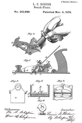
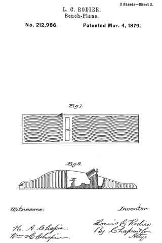
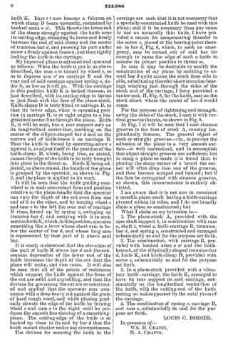
Referring to the drawings, which consist of two sheets and eight figures, Figure 1 is a longitudinal section of my plane. Fig. 2 is a perspective view of the knife-carriage and its operating-cam, showing its relative position to the hand of the operator while grasping the rear handle of the plane. Fig. 3 is a plan view of the knife-clamp and its set-screw. Fig. 4 is a view of the cam which actuates the knife-carriage, and the rear arm of the latter. Fig. 5 is a transverse section through the stock on the line x x, Fig. 1, showing the latter and the rear end of the carriage. Fig. 6 is a plan view of that portion of the stock embracing the throat thereof, with the carriage and trunnion-bar. Fig. 7 is a plan view of the face of the stock. Fig. 8 is a view partly of a side elevation and partly in section, showing a modified construction of the knife-rest.
Like letters of reference refer to like parts in the different figures.
A is the stock. B is the knife-carriage. c is a carriage-spring. d is the trunnion-bar. b is a cam-shaft support. e is a spoked cam-shaft wheel. i is the cam-shaft. o is the cam. h is a knife-brace on carriage B. n n’ are hooked arms on carriage B. D is the knife-clamp. s is the knife-clamp screw. t t are ears on the knife-clamp. m is the throat of the plane. a’ is the rear end of carriage B, under I cam o. z is a screw in trunnion-bar, d. K is the knife. H, Fig. 8, is a knife-rest just back of throat m.
I cast my plane-stock and fit to it the usual handle and front knob. Just forward of the handle I cast a cam-shaft support, b, into which I fit a cam-shaft, i, and secure to its rear upper end a wheel, e, and to its lower end cam o. Through the sides of stock A, opposite each other, I drill two holes for the reception of trunnion-shaft d. Carriage B is made to it between the sides of stock A, back of throat m, as shown, and is drilled so that it may be mounted on trunnion-bar d in its place in stock A, and is provided with a vertical knife-brace, h, and a rearwardly-projecting arm, a’, under cam o, and its sides rise up and turning backward form hook-shaped arms n n’.
Trunnion-shaft d has its ends and its center turned of about equal diameters; but between its center and the sides of the carriage B its diameter is reduced, so that its diameter centrally between said sides is the greatest. Thus fitted and arranged, carriage B and trunnion-bar d are placed in stock A, and said carriage has a vibratory motion therein, pivoted on said bar d.
In Fig. 5 it will be seen that the interior of stock A is made with its bottom the highest in the middle at the place there shown. The rear end of carriage B reaches over said highest part, and lying under said carriage, its sides resting on the ends thereof, is a spring, c, having a bearing midway between its ends on said highest part of the bottom of stock A, as seen in Fig. 5.
Knife-clamp D is made of the form shown, being of the same width as the distance between the sides of carriage B, provided with projecting ears t t on its edges and a set-screw, s, through its upper end.
When knife K is put into the plane its lower end bearing just above its cutting-edge rests upon the center of trunnion-bar d, with its cutting-end in the throat m of the stock, and just above, it finds a bearing on knife-brace h. Knife-clamp D is now placed on top of knife K, and slid down until its ears t t engage under the hooked arms n n’ on carriage B. In this position set-screw s is turned down against knife K. Ears t t now become a fulcrum on which clamp D bears upwardly, restrained by hooked arms n n’. This throws the lower end of the clamp strongly against the knife near its cutting-edge, clamping its lower end firmly between the end of said clamp and the center of trunnion-bar d, and pressing its part under screw s firmly against brace h, and thus rigidly locking the knife to the carriage.
My improved plane is adjusted and operated as follows: When the knife is put in as above described, the cam o is turned by wheel e, so as to depress arm a’ on carriage B and the rear end of said carriage against spring c, under it, as low as it will go. With the carriage in this position knife K is locked thereon, as just described, with its cutting-edge in throat m just flush with the face of the plane-stock. Knife-clamp D is truly fitted to carriage B, so that its lower edge, when in operating position in carriage B, is at right angles to a longitudinal center-line through the plane. Knife K, it will be seen, has a rear support only on its longitudinal center-line, touching on the center of the elliptic-shaped bar d and on the narrow end of knife-brace h, on carriage B. Thus the knife is forced by operating-screw s against it, to adjust itself to the position of the knife-clamp D, which, being true, as stated, causes the edge of the knife to be truly brought into place in the throat m. Knife K being adjusted, as above stated, the handle of the plane is grasped by the operator, as shown in Fig. 2, and the plane is applied to its work.
It will be seen that the knife guiding cam-wheel is in such convenient form and position relative to the plane-handle that the operator can vary the depth of the cut even from one end of it to the other, and by turning wheel e and cam o to the left the rear end of carriage B rises, forced up by spring c, swinging on trunnion-bar d, and carrying with it in such motion knife K, which, in this position, operates something like a lever whose short arm is below the center of bar d, and whose long arm is represented by that part of it above said bar.
It is easily understood that the elevation of the part of knife K above bar d and the consequent depression of the lower end of the knife increases the depth of the out that the plane will make, and vice versa. It will also be seen that all of the points of resistance which support the knife against the force of the cut are solid and unyielding, and that the devices for governing the cut are so constructed and applied that the operator may commence with a deep heavy cut against the grain of hard tough wood, and while planing gradually elevate the edge of the knife by turning wheel e and cam o to the right until he produces the smooth fine shaving of a smoothing-plane. The cutting-edge of the knife is so backed up close to its end by bar d that the knife cannot chatter under any circumstances.
The devices for securing the knife to the carriage are such that it is not necessary that a specially-constructed knife be used with this plane; and if it be necessary from any cause to use an unusually thin knife, I have provided a means for compensating therefor in the screw z, placed at the bearing-point thereon in bar d, Fig. 6, which, in such an emergency, may be turned out of said bar far enough to cause the edge of such a knife to assume its proper position in throat m.
In case it may be desirable to modify the construction of my plane by omitting to extend bar d quite across the stock from side to side, substituting therefor short trunnion-bearings reaching just through the sides of the stock and of the carriage, I have provided a center-rest, H, Fig. 8, for the knife, cast on the stock about where the center of bar d would come.
For the purpose of tightening and strengthening the sides of the stock, I cast it with vertical grooves therein, as shown in Fig. 8.
In Fig. 7 it will be seen that I cast sinuous grooves in the face of stock A, running longitudinally thereon. The general object of such or straight grooves — viz., to prevent the adhesion of the plane to a very smooth surface — is well understood, and to accomplish that object straight grooves are sufficient; but in using a plane so made it is found that in planing the sharp corner of a board the corner will often drop into one of the grooves, and thus become scraped and injured; but if the face be corrugated with sinuous grooves, as shown, this inconvenience is entirely obviated.
I am aware that it is not new to construct a metallic plane-stock having a knife-carriage pivoted within its sides, and I do not broadly claim a plane so constructed; but
What I claim as my invention is —
1. The plane-stock A, provided with the cam-shaft support b, in combination with cam o, shaft i, wheel e, knife-carriage B, trunnion-bar d, and spring c, constructed and arranged substantially as and for the purpose set forth.
2. The combination, with carriage B, provided with hooked arms n n’ and the knife-brace h, of the elliptically-shaped trunnion-bar d, knife K, and knife-clamp D, provided with screw S, substantially as and for the purpose set forth.
3. In a plane-stock provided with a vibratory knife- carriage, the knife K, arranged to have its rear support on said carriage, substantially on the longitudinal center-line of the knife, with the cutting-end of the knife resting on and supported bythe axial pivot of the carriage.
4. The combination of spring c, carriage B, and cam o, substantially as and for the purpose set forth.
LOUIS C. RODIER.
In presence of–
WM. H. CHAPIN,
H. A. CHAPIN.