
No. 315,014 – Bench-Plane (James Duncan) (1885)
UNITED STATES PATENT OFFICE.
_________________
JAMES DUNCAN, OF COSHOCTON, OHIO, ASSIGNOR TO HIMSELF,
WILLIAM W. BOSTWICK, AND FRANK C. HAY, ALL OF SAME PLACE.
BENCH-PLANE.
_________________
SPECIFICATION forming part of Letters Patent No. 315,014, dated April 7, 1885.
Application filed January 24, 1885. (No model.)
_________________
To all whom it may concern:
Be it known that I, JAMES DUNCAN, a citizen of the United States, residing at Coshocton, in the county of Coshocton and State of Ohio, have invented certain new and useful Improvements in Planes; and I do declare the following to be a full, clear, and exact description of the invention, such as will enable others skilled in the art to which it appertains to make and use the same, reference being had to the accompanying drawings, and to the letters and figures of reference marked thereon, which form a part of this specification.
This invention has for its object to improve the bench plane and scraper for which Letters Patent were granted to myself and Wm. H. Talbot, November 24, 1874, and numbered 157,162; and it consists in the construction and arrangement of the several parts, as hereinafter fully described and claimed.
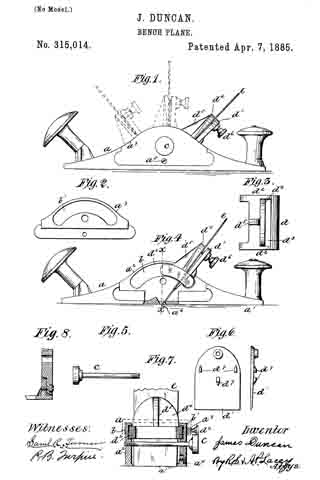
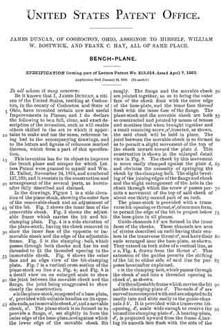
In the drawings, Figure 1 is a side elevation of the plane-stock, showing the outer face of the removable cheek and an adjustment of of the bit. Fig. 2 shows the inner face of the removable cheek. Fig. 3 shows the adjustable frame which carries the bit and bit-clamping plate. Fig. 4 is a side elevation of the plane-stock, having the cheek removed to show the inner face of the opposite or immovable cheek and the edge of the adjustable frame. Fig. 5 is the clamping-bolt, which passes through both cheeks and has its end threaded to fit the threaded opening in the immovable cheek. Fig. 6 shows-the outer face and an edge view of the bit-clamping plate. Fig. 7 is a vertical cross-section of the plane-stock on line x x, Fig. 4; and Fig. 8 is a detail view on an enlarged scale to show the joint between the movable cheek and the flange, the joint being exaggerated to show clearly the construction.
a is the plane-stock, composed of a-base-plate, a’, provided with suitable handles on its opposite ends, an im movable cheek, a2, and a movable cheek, a3. The plane-stock is so formed as to provide a flange, a4, set slightly in from the outer edge of the base-plate, and against which the lower edge of the movable cheek fits snugly. The flange and the movable cheek are jointed together, so as to bring the outer face of the cheek flush with the cuter edge of the base-plate, and the inner face thereof flush with the inner face of the flange. The plane-stock and the movable cheek are both so constructed and jointed by means of tenons and mortises that when brought together and a small retaining-screw, a5, inserted, as shown, the said cheek will be held in place. The joint between the movable cheek is so formed as to permit a slight movement — of the top of the cheek inward toward the plate d. This construction is shown in the enlarged detail view in Fig. 8. The cheek by this movement is more easily clamped against the plate d, and obviates the necessity of springing the cheek by the clamping-bolt. The slight beveling of the joining edges of the flange and cheek and the slight enlargement of the hole in the cheek through which the screw of passes permits a movement of the top of said cheek. of about one thirty-second part of an inch.
The plane-stock is provided with a transverse bit-opening or throat, a6, of common form, to permit the edge of the bit to project below the base-plate in all planes.
Guide-channels b b’ are formed in the inner faces of the cheeks. These channels are arcs of circles described on radii having their centers in the transverse throat a6, and have their ends arranged near the base-plate, as shown.
They extend on both sides of a vertical line, as x x, Fig. 4, drawn from the throat a6. This extension of the guides permits the shifting of the bit to either side of said line for purposes hereinafter explained.
c is the clamping-bolt, which passes through the cheek a3 and into a threaded opening in cheek a2, as shown.
d is the adjustable frame which carries the bit and the clamping-plate d’. The ends d2 d2 are curved to correspond with and are adapted to fit neatly into and slide easily in the guide-channels b b’. It is provided with a transverse bit-opening, d3, made wide enough to receive the bit and the clamping-plate d’. A bearing-plate, d4, is projected upward from the frame d, having its smooth face flush with the side of the opening d3, and arranged on a radial line having its center in the throat a6. This plate d4 is suitably braced on its back by a rib, d5. The bit e lies against the smooth face of the plate d4, and is held by a set-bolt, d6, threaded in the upper end of the clamping-plate d’, as shown.
The clamping-plate d’ has its face next the bit e made smooth, and on its back are provided a series of lugs, d7, so arranged that part of them will be on the upper side of and the others below the plate d. The clamping-plate is held from moving vertically by these lugs, and at the same time will have all the needed horizontal movement of its ends, whereby it is adjusted to the position of bit e. The adjustable frame is put in position in the bit-stock by removing the cheek a3 and placing the curved edges d2 in the guide-channels. The screw a5 holds the cheek a3 in place after the latter is put into position. The clamping-bolt c binds the jaws against the edges of the frame d, and holds the latter in any desired position.
In adjusting the plane the bit-plate d’ is first placed in the slot d3, and its lugs are properly engaged upon the frame. The bit is then inserted between the plates d’ and d4, and after being set properly is clamped in place by the set-bolt d6.
In this device the operation of setting the bit, whether for planing or scraping, is very much simplified. By slightly loosening the bolt c the frame d can be moved to give to the bit any desired set, inclined or vertical. By taking the bolt c out the frame d can be moved to throw the bit inclined toward the opposite end of the stock, as shown in dotted lines, when such a set is desired.
To convert the tool into a smoothing-plane, the bolt c is arranged below the plane of movement of the frame d, so that no interference ever occurs between these two parts.
The channels b b’ hold the frame d securely against vertical movement, but permit the free longitudinal movement for purposes of adjustment of the bit to the desired angle.
Instead of the clamping bolt c, a movable clamp may be employed having two jaws to slide down over the upper edges of the cheeks and be held in place by friction, or by a set-screw, or by any well-known means. Such a clamp is indicated in dotted lines in Fig. 7. I do not prefer such a clamp, as it would be somewhat troublesome in use; but I do not limit myself to the clamping-bolt c as a means for clamping the cheeks against the bit carrying frame.
Having thus described my invention, what I claim, and desire to secure by Letters Patent, is —
1. The improved planing implement hereinbefore described, having cheeks provided with guides made in the arc of a circle extended on opposite sides of a line vertical to the throat in the base-plate, a bit-carrying frame supported by the guides, and movable thereon to either side of the vertical line aforesaid, and a clamp, substantially as and for the purposes set forth.
2. In a bench plane or scraper, the improved bit-carrying frame composed of the main frame adjustable longitudinally in the stock and provided with a transverse slot or bit-opening and having a bearing-plate projected upward flush with the front side of the opening, a clamping-plate supported loosely in the bit-opening in and carried by the main frame, and having on its rear side lugs or retaining means, which engage on and hold it from vertical movement in the frame, and a clamping-bolt threaded in the upper end of the clamping-plate to clamp the bit against the fixed bearing-plate, substantially as set forth.
3. The combination of the stock provided on one side with a flange, a4, and on its other side with the immovable cheek a2, having in its inner face a guide-channel formed on the are of a circle, a removable cheek, a3, having its lower edge loosely jointed with and secured to the flange a4, so that its top portion may be slightly inclined inward, and having in its inner face a guide-channel formed in the arc of a circle parallel with and corresponding to the guide-channel in the inner face of the immovable cheek, a sliding bit-carrying frame having curved end guides, d2, fitted into the guide-channel in the cheeks, and a stationary clamping-bolt passed through the cheeks midway the lower and upper edges thereof, substantially as and for the purposes set forth.
4. The bench plane and scraper hereinbefore described, composed of the base-plate, the two jaws, one of which is movable, having formed therein curved guide-channels having their ends approximately at the lower edges of the cheeks, a bit-carrying frame having its edges fitted into the guide-channels and adjustable longitudinally from one end to the other thereof, whereby it may be set to carry a plane-bit or a scraper-bit and a clamping device, substantially as set forth.
In testimony whereof I affix my signature in presence of two witnesses.
JAMES DUNCAN.
Wtnesses:
J. S. ELLIOTT,
J. H. ASKREN.
Correction in Letters Patent No. 315,014
It is hereby certified that in Letters Patent No. 315,014, granted April 7, 1885, upon the application of James Duncan, of Coshocton, Ohio, for an improvement in “Bench-Planes,” the name of one of the assignees was inadvertently omitted; that said patent should have been issued to James Duncan, Jesse P. Forbes, William W. Bostwick, and Frank C. Hay; and that the proper correction has been made in the files and records of the case in the Patent Office, and should be read in the said Letters Patent to make it conform thereto.
Signed, countersigned, and sealed this 14th day of April, A. D. 1885.
[SEAL]
H. L. MULDROW,
Acting Secretary of the Interior.
Countersigned:
M. V. MONTGOMERY,
Commissioner of Patents.