No. 143,072 – Improvement In Bench-Planes (Cyrus H. Hardy) (1873)

[paiddownloads id=”216″]143072


UNITED STATES PATENT OFFICE.

_________________

CYRUS H. HARDY, OF BOSTON, MASS., ASSIGNOR TO JOHN SULLY, TRUSTEE.

IMPROVEMENT IN BENCH-PLANES.

_________________

Specification forming part of Letters Patent No. 143,072, dated September 23, 1873; application filed May 28, 1873.

_________________

To all whom it may concern:

Be it known that I, CYRUS H. HARDY, of Boston, in the county of Suffolk and State of Massachusetts, have invented certain Improvements in Bench-Planes, of which the following is a specification:

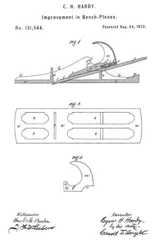
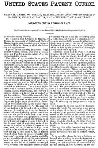
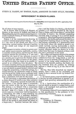
Figure 1 of the accompanying drawing is a central vertical longitudinal section. Fig. 2 is a top view of the shield, and Fig. 3 is a transverse vertical section through a portion of the shield and wedge of my improved plane.

The present invention relates to certain new and useful improvements, applicable, mainly, to metallic bench-planes, and having for their principal objects the providing of a rest and shield for the hand of the operator, to serve as a handle, and to prevent the friction of the hand against the sides or frame of the plane, as well as to allow the blade to be readily inserted in or withdrawn from the plane. My invention consists, mainly, in a plane arranged as will be hereinafter more fully described, with a curved shield or guard formed with forward wedge-like projections, or beveled prongs, inserted between an adjustable wedge or block and the top of the blade, so as to securely hold or be readily withdrawn from the latter and form a protection and rest for the hand.

In the drawings, a represents the bottom of a plane, formed of metal or any other suitable material. Projecting upward on each side of the bottom a are curved sides b, connected near the center at the top by a cross-bar, c. The bottom a is formed with a transverse mouth or slot, d, that receives the front “top-beveled” edge of a blade, e, the bottom of which rests on a transverse vertical standard, f, connecting the sides b, and extending up from the bottom a at a sufficient distance from the rear end of the frame to give a proper angle to the blade e. Extending upward, in front of the mouth d, and across the plane, is a finger-rest, l. Inserted between the cross-bar c and the blade e is a block, g, the forward portion g’ of which is beveled on the top to form a wedge, and whose edges g” are beveled inwardly to receive the forward-projecting beveled ends or prongs Ih’ of a curved shield or guard, h. The projecting ends or prongs h’ are beveled on the inside, and extend forward in a longitudinal tapering shape on the top, with a flat bottom, extending in a semicircular form at the back, where the shield or guard It extends upward, curving horizontally a short distance on the sides, and vertically in a segmental elliptical shape, as shown, or in any other form that may be desired, to form a rest for and a protection to the hand.

The wedge and tapering shape of the prongs h’ allow of their ready insertion between or withdrawal from the wedge-block g and the blade e, so as to securely hold the latter, or to permit of its being easily withdrawn or adjusted to the desired position, the blade e being loosened from its position by striking against a block or lug, m, at the rear of the plane.

Having thus fully described my improvements, what I claim as my invention, and desire to have secured to me by Letters Patent, is —

1. In a bench-plane, a curved shield or guard, lt, having beveled projections or prongs h’, arranged and operating substantially as specified.

2. In a bench-plane, the combination of a curved shield or guard, h, wedge-block g, and blade e, all arranged and operating substantially as described.

In testimony whereof I have signed my name to this specification in the presence of two subscribing witnesses.

CYRUS H. HARDY.

Witnesses:
CARROLL D. WRIGHT,
SAML. M. BARTON.

No. 131,544 – Improvement In Bench-Planes (Cyrus H. Hardy) (1872)

[paiddownloads id=”202″]131544


UNITED STATES PATENT OFFICE.

_________________

CYRUS H. HARDY, OF BOSTON, MASSACHUSETTS, ASSIGNOR TO JOSEPH F.
BALDWIN, MELINA C. PATTON, AND JOHN LULLY, OF SAME PLACE.

IMPROVEMENT IN BENCH-PLANES.

_________________

Specification forming part of Letters Patent No. 131,544, dated September 24, 1872.

_________________

To all whom it may concern:

Be it known that I, CYRUS H. HARDY, of Boston, in the county of Suffolk and State of Massachusetts, have invented certain Improvements in Metallic Planes, of which the following is a specification:

Figure 1 of the drawing is a central longitudinal vertical section, Fig. 2 is a bottom view, and Fig. 3 is a part in detail, of my improved metallic planes.

The object of my invention is to provide means for the ready adjustment of the blade of a plane; and it consists in so forming an adjustable shield, in connection with a wedge-block and sides of the plane-frame, to allow a blade to be readily adjusted in or withdrawn from the frame.

In the drawing, a represents the bottom of a frame of a metallic plane, the weight of which is diminished by the formation of openings or slots b, which may be of any form or size, arranged as may be desired, and either left open or filled with wood or other light material or substance. The bottom a is provided with a suitable mouth, c, and has extending across, transversely, and upward a suitable distance, a finger-bar or rest, d, of any desired form. Toward the rear end of the frame is a vertical transverse bar or standard, e, extending upward to the height required to give the proper angle to a blade, f, the bottom of which rests upon it, and whose edge is formed by an upward bevel, f’. The rear end of the bottom a, is formed with a striking-block, g. Extending up from the bottom a are curved sides h, sloping upward toward the center of the plane, where each is cut away so as to leave on the top a projection, i, curved on the under side to admit the turning of an upward-curved portion or cam, k, formed by the forward part of projecting ends of the bottom of a shield, m, which is curved at the sides, back, and top, as shown in Figs. 1 and 3, and has its bottom cut away, as at n, to fit over the top of the blade f and is formed with a bottom frame or plate, o, provided with bearings o’, in which a bolt, p, having a suitable spring, p’, and thumb piece p” , is made to travel back and forth, in and out of a socket, x, formed in the end of a beveled or wedged block, r, formed to it within the curved front of the frame or plate o and the projecting sides l, to the latter of which it is attached by pivots s, or other suitable means, for allowing the shield on to turn over the top of the block r, the bottom of which rests upon the blade f, which is held by the pressure of the wedge-block r and cam k upon it.

Reference being had to Figs. 1-3 of the drawing, it will be seen that, by unlocking the bolt p from the block r, the shield m is, by the action of the cams k and pivot s or its equivalent, allowed to turn over the top of the block r, which is, by the operation, carried up, and lessens its hold on the blade f, which may then be easily withdrawn or adjusted in the desired manner. When the blade f is inserted in the position required the bolt p is unlocked from the wedge-block r, the shield m is turned by the action of the cam k onto the blade f which is securely held by the wedge-block r and cam k, and forms a guard that serves as a support to the hand, the fingers of which find a hold on the forward rest or bar d. The principal function of the spring-bolt p is to prevent the liability of the tipping of the cam is or the forward projections l of the shield m when power is applied to the upper part of the back of the shield. Instead of the bolt p and spring p’, &c., a spring-clutch, or any other suitable device for holding and relieving the wedge-block r, may be used.

It will readily be seen that by my improvements the blade f is inserted at a low angle, which admits of its being readily withdrawn or adjusted, and permits the shield m, which serves as the handle, to be placed near the mouth and center of the plane, and thus prevents the rising of the forward part of the plane, which is often liable to occur when the handle is formed near the rear end of the plane.

Having thus fully described my improvements, what I claim as my invention, and desire to have secured to me by Letters Patent, is —

1. A metallic plane, having a bottom, a, formed with openings or slots b, finger-bar or rest d, curved sides h, arranged with projections i, and cut away so as to receive and admit the turning of cams k, formed by the projecting ends l of the bottom of a curved shield, m, provided with a bolt, p, and spring p’, or their equivalents, and connected with and operating a wedge-block, r, bearing on a blade, f supported by a standard, e, substantially as specified.

2. The shield m, having the recess n, and provided with the frame o, bearings o’, and cam k, and combined with the bolt and spring p p’, block r, frame a e h, and blade f all arranged and operating as described.

3. The wedge-block r, in combination with the shield m, bolt p, and spring p’, or their equivalents, blade f and sides in of a metallic plane, arranged and operated substantially as described.

In testimony whereof I have signed my name to this specification in the presence of two subscribing witnesses.

CYRUS H. HARDY.

Witnesses :
SAML. M. BARTON,
CARROLL D. WRIGHT.