
No. 127,026 – Improvement In Bench-Planes (Morgan Chittenden) (1872)
UNITED STATES PATENT OFFICE.
_________________
MORGAN CHITTENDEN OF DANBUBY IOWA.
IMPROVEMENT IN BENCH-PLANES.
_________________
Specification forming part of Letters Patent No. 127,026, dated May 9, 1872.
_________________
I, MORGAN CHITTENDEN, of Danbury, in the county of Fairfield and State of Connecticut, have invented certain Improvements in Bench-Planes, of which the following is a specifcation:
The object of this invention is to attach to the stock of a common bench or other plane an adjustable and removable guide or fence that can assume any desired angle with relation to the f’ace of the plane; and it consists in the construction and arrangement of the devices necessary to so attach and adjust the fence or guide, as will hereinafter be fully described.
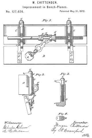
In the drawing, Figure 1 is a side view of a plane-stock guide, and the devices for clamping it to the stock, and adjusting it to different angles; Fig. 2 is an end view of same; Fig. 3 a side view of the clamp, and Fig. 4 a top sectional view of the same.
A represents the stock of the plane; B, the fence or guide. C is a portion of a clamp, by which the fence B is attached to the plane-stock by means of the strap-plate C’, that is made fast to the guide or fence, and is hinged to clamp-piece G at c”; on the lower end of clamp-piece C’ is a hook-like projection, c”’, that takes hold of the under or face side of the plane-stock, as seen in Figs. 2 and 3. D is a screw-rod, having a screw cut upon it a portion of its length from one end. E is a nut, fast on the screw-rod D, and by which the screw rod is turned. E’ is a swivel, having heads e’ e’ through which rod D freely turns, while on one side the connecting-bar has a holding~screw, e”, that holds the swivel fast upon the screw-rod at any desired point, on the opposite side of the swivel is plate f’. The swivel E’ is held to its place by collar e on one side and nut E on the other. F is a diagonal connecting-bar pivoted at f to plate f’, has a screw-swivel at f”, for the purpose of adjusting the length of the diagonal bar; and at the lower end of the screw-swivel is an eye that goes between ears f3 f3, and to which it is pivoted. G is a pivot-plate, pivoted to the outside of the fence or guide-piece B, and has cast upon it ears f3 f3, between which the swivel end of the diagonal connecting-rod or bar is pivoted, and by which the guide or fence is allowed to assume different positions with relation to the face of the plane. H is the upper part of the clamp, and has a hook. h, projecting from one side, and takes hold of the upper side of the plane-stock. This upper part of the clamp fits and slides into the lower and outer part C, and the two parts are held together only by screw h’ h’ is a screw, going longitudinally through clamp-piece H into clamp-piece C, and by turning up the screw brings the hooks h and c”’ nearer to each other, and consequently clamps the device fast upon the plane-stock. Screw-rod D freely slides and turns in a hole in a projecting rib on clamp part, G, at one ofthe clamps, as seen at c, while the screw part of the rod passes through a screw-nut in the other clamp-piece at c’.
The operation is as follows: After the device is clamped upon the plane-stock by turning screw h’ down hard, and thereby firmly securing the fence or guide to the stock by turning nut E, it will force the screw-rod D longitudinally in one direction or the other, carrying with it the upper end of the diagonal connecting-bar F, but by reason of the guide or fence B not moving longitudinally it is forced to turn on hinges c”, and turn outward, making an obtuse angle to the face of the plane; and by reversing the revolution of the nut E the rod D is forced in the reverse direction, and consequently the guide or fence B is pushed so as to form an acute angle to the face of the plane, thus making the fence conform to any angle desired, when it is held firmly in such angle by screw e”.
By this construction the fence or guide can be attached to and removed from any plane-stock without marring or defacing it, and saving much in the expense of having extra planes with the fence attached, as this can be made to be put upon or attached to any plane.
I claim as my invention —
1. The sliding-rod D, diagonal bar F, plate G, and guide or fence B hinged to clamps C C H H, in combination with the plane-stock A, constructed to operate as shown and described.
2. The combination of the parts C of the clamps, straps C’ hinged thereto, screw-rod D, turning-nut E, swivel E’, bar F and plate G with the fence or guide B, constructed to operate substantially as herein described.
3. Attaching the removable and adjustable fence or guide B to the plane-stock A, by means of the clamps formed of parts C, to which the guide is hinged, and H having hooks c”’ and h, and holding-screw h’, in the manner herein described.
MORGAN CHITTENDEN.
Witnesses:
DAVID B. BOODY,
ALFRED BELL.