No. 166,239 – Improvement In Bench-Planes (David F. Williams) (1875)

[paiddownloads id=”250″]166239


UNITED STATES PATENT OFFICE.

_________________

DAVID F. WILLIAMS, OF WOONSOCKET, RHODE ISLAND, ASSIGNOR TO BAILEY TOOL COMPANY, OF SAME PLACE.

IMPROVEMENT IN BENCH-PLANES.

_________________

Specification forming part of Letters Patent No. 166,239, dated August 3, 1875; application filed May 24, 1875.

_________________

To all whom it may concern:

Be it known that I, DAVID F. WILLIAMS, of Woonsocket, Providence Plantations, and in the State of Rhode Island, have invented a new and useful Improvement in Bench-Planes; and I do hereby declare that the following is a full, clear, and exact description thereof, reference being had to the accompanying drawings making a part of this specification.

This invention relates to a bench-plane having a flexible steel face to allow of its being adjusted to operate upon any given circle or arc of a circle in either a concave or convex form; and it consists in certain improvements in the mode of fixing or holding the face after it has been bent to the desired curve, substantially as hereinafter more fully set forth, the object being to simplify the construction of the plane, and at the same time to secure a firmer adjustinent of the flexible face.

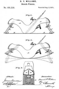
Figure 1 in the drawing shows the plane adjusted to operate upon a plane surface. Fig. 2 shows it adjusted to operate upon a concave surface, the dotted lines also indicating the position of the movable parts when the face is adjusted to operate upon a plane and on a convex surface. Fig. 3 is a front view, showing the opening in the stock and the slotted arm attached to the face-plate, which slides therein.

A in the drawings represents a metallic plane-stock, cast in the usual form for this class of planes. B is the flexible face of steel, made thinnest at its ends, and tapering from the center of its length, in order that when bent it may form a perfect curve. It is attached to the stock by means of screws on each side of the month of the plane. The ends of the plane-stock are split, as shown at a, Fig. 3, forming jaws E E, and, provided with set-screws D D, form clamps for the slotted arms C C’, which are attached, respectively, to the ends of the flexible shoe B. These screws pass through one side of the divided end of the plane-stock, and through the slot in said arms, and are screwed into threads formed in the other side or jaw of the clamp or stock, and, being provided with shoulders d, operate to tightly clamp the jaws. The arms C C’ are attached to the flexible shoe by being hinged at b to a piece, c, which is riveted to the shoe.

As the screws D are loosened, and the shoe B is bent in either direction the arms C C’ slide on the screws D in their slots, and permit the adjustment of the shoe to any desired curve.

The arm C’ is bent to prevent contact with the upper part of the plane-iron when the shoe is bent to a convex form.

What is claimed as the invention is —

1. A bench plane having a flexible face, in which the stock is split at either end to form a clamp, substantially as described.

2. The combination of the flexible shoe B, slotted arms C C’ hinged thereto, clamping-jaws E, and set-screws D, substantially as described.

D. F. WILLIAMS.

Witnesses:
WM. H. BAILEY,
J. E. BLOOD.

No. 166,240 – Improvement In Bench-Planes (David F. Williams) (1875)

[paiddownloads id=”251″]166240


UNITED STATES PATENT OFFICE.

_________________

DAVID F. WILLIAMS, OF WOONSOOKET, RHODE ISLAND, ASSIGNOR TO BAILEY TOOL COMPANY, OF SAME PLACE.

IMPROVEMENT IN BENCH-PLANES.

_________________

Specification forming part of Letters Patent No. 166,240, dated August 3, 1875; application filed May 24, 1875.

_________________

To all whom it may concern:

Be it known that I, DAVID F. WILLIAMS, of Woonsocket, Providence Plantations, and in the State of Rhode Island, have invented a new and useful Improvement in Bench-Planes; and I do hereby declare that the following is a full, clear, and exact description thereof, reference being had to the annexed drawings making part of this specification, in which —

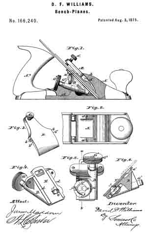
Figure 1 is a side elevation of my improved bench-plane, one of the cheeks of the stock being broken away to show more clearly the means for clamping and adjusting the bit. Fig. 2 is a plan view of the forward end of the stock. Fig. 3 is a perspective view of the clamping-plate and screw. Fig. 4 is a perspective view of the bit-adjusting mechanism. Fig. 5 is a view ofthe under side ofthe same. Fig. 6 is a section thereof, taken in planes indicated by the broken line x y in Fig. 5.

The same letters of reference are used in all the figures in the designation of identical parts.

The nature of my invention consists, first, in the employment of a clamping-plate and screw for fixing the bit after proper adjustment, the clamping-plate having open bearings at about its mid-length in its side edges, for the reception of fixed studs projecting inwardly from the cheekplates of the stock; secondly, in the use ofa sliding plate so combined with mechanism for sliding it in its seat, and the head of the screw used for securing the cap to the bit, as to afford a convenient means for accurately adjusting the bit with the right hand, while holding on to the tail-handle of the plane with the left.

The stock A, made of metal, in substantially the form shown, is provided with the usual throat, through which the bit projects, and also with inclined surfaces a, for supporting the bit in part. The bit is secured by a lever or clamping-plate, B, pivoted above it to the cheek-plates of the stock, and provided at its upper end with a set-screw, C, to press against the cap of the bit, thereby causing the lower end of the clamping-plate to also forcibly bear on the cap of the bit. It is pivoted upon short fixed studs a’, projecting inwardly from the cheek-plates of the stock, and is provided with open bearings b, formed in its side edges, in such a way that it may be slid upon said studs, which enter their bearings through chambers b’, formed in the under side of the clamping-plate. Supports for the plane-iron, having inclined surfaces a, against which said iron rests, are cast upon the inner side of each of the flanges of the stock A. Between these supports for the plane-iron, underneath the latter, is inserted a frame, D, which contains the mechanism by means of which the plane is adjusted, said frame being screwed to the supports referred to through ears cast thereon. The flanges of this frame D lie in the same plane as the supporting surfaces a, and assist in forming a bed for the plane-iron. Between the flanges is a plate, E, which slides in dovetailed grooves formed in said flanges. This plate has a notch, e, which receives a crank-pin, f This crank-pin projects eccentrically from the hub of a sectional worm-wheel, F, arranged in a recess in the under side of frame D. Wheel F meshes into a worm, G, on a shaft, GI, which turns in a bearing of frame D, and is provided at its outer rear end with a milled head or button, G2, which secures the cap to the bit.

The plate E moves in a plane parallel to the bit-supporting surfaces, so that by sliding it by means of the crank and worm-gearing described, the bit may be accurately and readily adjusted.

The non-toothed portion of the worm-wheel F is of smaller radius than the toothed portion, forming shoulders f1 at the junction, which bring up against a stop-pin, f2, whenever the worm-wheel has been turned in either direction to the extent of the throw of the crank-pin f.

The milled head or button G2 is in convenient proximity to the tail-handle A2 of the stock, for operating it with the thumb and fingers of the right hand, while holding on to the tail-handle.

In addition to its described function of moving the plate E., the worm-gearing constitutes a lock, holding the plate, and consequently the bit connected to it, by means of the head of screw H, firmly in position against sliding, thus assisting the clamping-plate in this office.

I do not claim a cap or presser plate made to slide in grooves formed in the sides of the stock, as shown and described in the patent, now expired, granted W. S. Loughborough, April 4, 1854.

What is claimed as the invention is —

1. In a bench-plane, a clamping-plate having open bearings in its side edges, with channels leading thereto in its under side. substantially as and for the purpose set forth.

2. The combination of the stock A, with studs a’, the bit and its cap, and the clamp-
ing-plate B, with channeled openings b b’, substantially as described.

3. In a bench-plane, the combination of the sliding plate, crank-pin, worm, and worm-wheel, substantially as described.

4. The combination of the plane-iron and its cap, the uniting-screw, and the slotted sliding plate with means for operating the same, substantially as described.

5. The sectoral worm-wheel F, having shoulders at f1 f1, in combination with the stop-pin f2 and the worm G G1, substantially as described.

D. F. WILLIAMS.

Witnesses:
WM. H. BAILEY,
J. E. BLOOD.
No. 144,381 – Improvement In Bench-Planes (William H. Brown And David F. Williams) (1873)

[paiddownloads id=”219″]144381


UNITED STATES PATENT OFFICE.

_________________

WILLIAM H. BROWN, OF WORCESTER, MASSACHUSETTS, AND DAVID F.
WILLIAMS, OF WOONSOCKET, ASSIGNORS TO BAILEY TOOL COMPANY, OF WOONSOCKET, RHODE ISLAND.

IMPROVEMENT IN BENCH-PLANES.

_________________

Specification forming part of Letters Patent No. 144,381, dated November 11, 1873; application filed April 12, 1873.

_________________

To all whom it may concern:

Be it known that we, WM. H. BROWN, of Worcester, in the county of Worcester and State of Massachusetts, and DAVID F. WILLIAMS, of Woonsocket, in the county of Providence and in the State of Rhode Island, have invented a new and useful Improvement in Bench-Planes; and we do hereby declare that the following is a full, clear, and exact description thereof, reference being had to the annexed drawings making a part of this specification, in which —

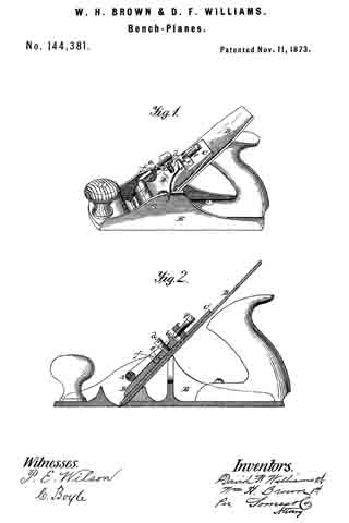
Figure 1 represents our improved bench-plane in perspective, and Fig. 2 a vertical longitudinal section of the same.

Our invention consists in certain hereinafter-described means provided for the purpose of facilitating the adjustment of the cap, and for regulating the pressure upon the cutting-tool.

The general construction of our bench-plane is like that described in Letters Patent No. 105,767, granted Joseph R. Bailey, July 26, 1870, an eccentric or curved bar, A, being used in conjunction with a presser-plate, B, to secure the plane-iron D and intervening cap C in the stock E. The presser-plate in this case is elongated and provided with a head, D, and a set-screw, d, the former of which acts in conjunction with other parts presently to be described, while, by means of the lathe, the pressure of said plate against the cam-rod may be adjusted so as to permit of the use of a thick or thin cap or cutting-iron, as desired. It also has lugs e, which project into grooves f cut in each side of the flanges of the stock, at right angles to the cutting-tool, whereby the slipping or sliding of the plate forward or backward is prevented, while at the same time it is allowed to rise and fall under the action of the set-screw d. The accurate adjustment of the cap with reference to the cutting edge of the chisel and the throat of the stock is obtained by means of a set-screw, F, which is carried in a screw-threaded eye in ear c of the cap, and bears with its point against the head b of the presser-plate. The foot of set-screw F being pointed, as shown, a V-shaped groove is formed in the end of head b, to receive such point, and allow the presser-plate to rise and fall and keep it in its exact position.

In the adjustment of the parts, the cap should be properly arranged by adjusting the set-screw F before the eccentric bar is turned down to force the presser-plate against the cap.

We claim as our invention —

1. In a bench-plane of the character described, an adjusting-screw, F, working in an ear, c, formed on or attached to the cap, combined with the presser-plate B, provided with the grooved head b, substantially as and for the purpose set forth.

2. The eccentric A, presser-plate B with lugs e e, grooves f f, and set-screw d, in combination with the cap or plane-iron.

3. The presser-plate B, with lugs e e, in combination with cap C c, set-screw F, and grooves f f substantially as described.

In testimony that we claim the above-described improvement we have hereunto signed our names this 5th day of April, 1873.

WM. H. BROWN.
DAVID F. WILLIAMS.

Witnesses:
F. T. BLACKMER,
W. W. RICE.