No. 830,541 – Bench-Plane (Justus A. Traut) (1906)

[paiddownloads id=”635″]830541


UNITED STATES PATENT OFFICE.

_________________

JUSTUS A. TRAUT, OF NEW BRITAIN, CONNECTICUT, ASSIGNOR TO STANLEY RULE &
LEVEL COMPANY, OF NEW BRITAIN, CONNECTICUT, A CORPORATION OF CONNECTICUT.

BENCH-PLANE.

_________________

830,541. Specification of Letters Patent. Patented Sept. 11, 1906.
Application filed May 26, 1906. Serial No. 318,812.

_________________

To all whom it may concern:

Be it known that I, JUSTUS A. TRAUT, a citizen of the United States, residing at New Britain, county of Hartford, Connecticut, have invented certain new and useful Improvements in Planes, of which the following is a full, clear, and exact description.

My invention relates to improvements in tools, and particularly planes for carpenters’ and joiners’ use.

The object of the invention is to provide a stop or gage for limiting the cutting depth and steadying the plane when in operation.

Various gages and stops have previously been employed in tools of this character, but for some classes of work they fail to give proper support to the plane when in operation.

The preferred form of the invention is illustrated in the accompanying three sheets of drawings.

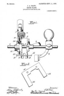
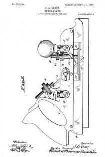
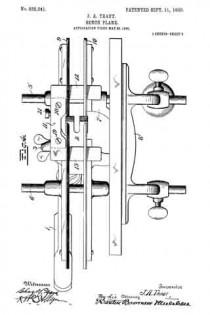
Figure 1 is an end view of a plane embodying the improvements of my invention. Fig. 2 is a detail perspective view of a part of the gage. Fig. 3 is a side view of a plane with gage attached. Fig. 4 is a bottom plan view.

1 is the main body or handle member.

2 is the plane-iron having a suitably-formed cutting edge in accordance with the cross-section of the product desired. This iron is clamped in place by a suitable mechanism, such as 3, and may be adjusted by a suitable mechanism, such as 4.

5 and 6 are cross-rods clamped to the body in a suitable manner.

7 is an auxiliary clamping and supporting member for the plane-iron, which is clamped on the rods 5 and 6 by suitable mechanism.

8 is a fence customarily employed with planes of this character for guiding it laterally in operation. The main and auxiliary portions of the plane are provided with guide-flanges 9 and 10. A plane-iron of any width may be employed with this tool, the body and auxiliary members being adjusted laterally with respect to one another.

11 is the gage or stop the use of which my invention particularly contemplates. This stop has laterally-extending arms 12 and 13, which project through openings, such as 14 and 15, in the guide-flanges 9 and 10.

16 is a screw-threaded post having a foot 17, to which the gage 11 is secured by means of screws 18 and 19.

The post and gage may be vertically adjusted by the screw 20 and clamped in position by the screw 21. When the gage is being vertically adjusted, it is guided and prevented from rotating on its post by reason of its construction and coaction with the guide-flanges 9 and 10. By reason of the bearing-surfaces provided by the arms 12 and 13 in front and in rear ofthe cutting-iron and the lateral extensions outside of each guide-flange the tool is prevented from tilting forward and back or sidewise when in operation.

The gage may be adjusted to suit the depth of cut desired and may be readily removed upon releasing the screws 18 and 19, in which event the foot 17 acts as a gage, which maybe adjusted for work requiring the gage only on one side. The arms 12 and 13 being formed in one piece with the main body 11 of the gage, the entire bearing area remains in a single plane and is consequently adjusted vertically with uniformity in front and in rear of the plane-iron. This is an advantage which would not be present were the two arms 12 and 13 carried by separate adjusting-posts.

What I claim is —

1. In a plane, a body, auxiliary members having depending guide-flanges with passages in said flanges, and a gage extending laterally through said passages.

2. In a plane, a body and auxiliary members laterally adjustable with relation to one another and adapted to support a plane-iron, a vertically-adjustable post, and a gage carried thereby having members extending in front and in the rear of the plane-iron position and laterally beyond the edges of the plane-iron.

3. In a plane, a body having a depending flange, a plane-iron carried by the body, an adjustable post carried by the body, and a gage carried by said post having an arm extending through the flange in front of the plane-iron.

4. In a plane, a body, an iron clamped thereto, a depending iiange from said body, an auxiliary member laterally adjust able with respect thereto, a depending guide-flange carried by said auxiliary member, and a vertically-adjustable gage in the rear of the plane-iron position extending through said flanges.

5. In a plane, main and auxiliary sections, depending flanges carried thereby, a plane-iron held between said sections, a vertically-adjustable post having a foot, and a gage removably secured to said foot and having an arm extending through said flanges.

6. In a plane, main and auxiliary sections, depending flanges carried thereby, a plane-iron held between said sections, a vertically-adjustable post having a foot, and a gage removably secured to said foot and having arms extending through said flanges in front and in the rear of the plane-iron.

7. As an article of manufacture, a plane-gage attachment comprising a body, means of attachment to a plane, and laterally-extending arms carried by the body spaced apart from each other and lying in the same plane with the body.

JUSTUS A. TRAUT.

Witnesses:
W. J. WORAM,
H. S. WALTER.

No. 820,639 – Plane (Andrew N. Gabrielson) (1906)

[paiddownloads id=”632″]820639


UNITED STATES PATENT OFFICE.

_________________

ANDREW N. GABRIELSON, OF MOUNT IRON , MINNESOTA.

PLANE.

_________________

820,639. Specification of Letters Patent. Patented May 15, 1906.
Application filed December 18, 1905. Serial No. 292,203.

_________________

To all whom it may concern:

Be it known that I, ANDREW N. GABRIELSON, a citizen of the United States, residing at Mount Iron, in the county of St. Louis, State of Minnesota, have invented certain new and useful Improvements in Planes; and I do hereby declare the following to be a full, clear, and exact description of the invention, such as will enable others skilled in the art to which it appertains to make and use the same.

This invention relates to planes, and more particularly to hand-planes, and has for its object to provide a plane which may be used either as a jack-plane or a smoothing-plane and which will be provided with guides arranged for movement into and out of position to lie against the working face of the board to insure even planing of the edges thereof.

Other objects and advantages will be apparent from the following description.

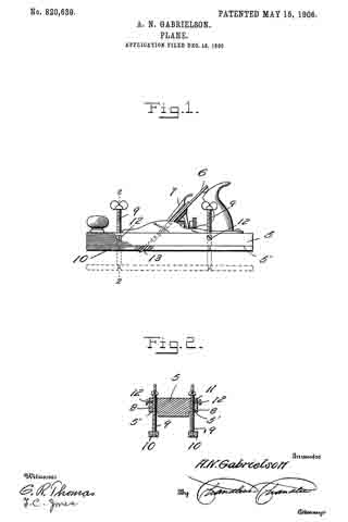
In the drawings forrning a portion of this specification, and in which like numerals of reference indicate similar parts in both views, Figure 1 is a side elevation of the present plane with the guides in the rabbets and showing them in lowered position in dotted lines. Fig. 2 is a transverse section on line 2 2 of Fig. 1, the guides being lowered.

Referring now to the drawings, the present invention comprises a body 5 and bits 6, provided with the usual bit-adjusting mechanism 7. The body 5 has longitudinal rabbets 5′ at its lower side angles, and communicating with each of these rabbets there are forward and rearward vertical threaded passages 8, in which are adjustably engaged set-screws 9, the lower ends of the set-screws being revolubly engaged in guides 10, which extend longitudinally of the body 5 and which are adapted to lie in the rabbets 5’. The arrangement is such that the set-screws may be operated to move the guides 10 into and out of the rabbets, and when both guides are in the rabbets the plane may be used in the ordinary manner. When the edge of a board is to be planed, one of the guides is lowered to rest against the working face of the board, and thus planing of the edge at right angles to the working face is assured.

Laterally-extending threaded passages 11 communicate with the passages 8 and open through the side faces of the body, and in these passages 11 there are engaged screws 12, which are operable to impinge against the set-screws 9 to hold the latter, with the guides, at different points of their movement. In their mutually-adjacent faces the guides have recesses 13, which receive the edge portions of the bit 6 when the guides are in the rabbets.

What is claimed is —

In a plane, the combination with a body having longitudinal rabbets at its lower side angles and having vertical threaded passages communicating with the rabbets, of set-screws engaged in the passages, guides connected with the lower ends of the set-screws for rotation of the latter with respect thereto, said set-screws being operable to move the guides into and out of the rabbets, and means for holding the set-screws with the guides at different points of their movement.

In testimony whereof I affix my signature in presence of two witnesses.

ANDREW N. GABRIELSON.

Witnesses:
VICTOR I. FRASER,
F. J. JOHNSON.

No. 469,688 – Attachment For Planes (Addison J. Ferris) (1892)

[paiddownloads id=”484″]469688


UNITED STATES PATENT OFFICE.

_________________

ADDISON J. FERRIS, OF EAST HAMPTON, MASSACHUSETTS.

ATTACHMENT FOR PLANES.

_________________

SPECIFICATION forming part of Letters Patent No. 469,688, dated March 1, 1892.
Application filed April 13, 1891. Serial No. 388,672. (No model.)

_________________

To all whom it may concern:

Be it known that I, ADDISON J. FERRIS, a citizen of the United States, residing at East Hampton, in the county of Hampshire and State of Massachusetts, have invented new and useful Improvements in Attachments for Planes, of which the following is a specification.

This invention relates or has reference to improvements in planes which are especially designed for finishing rabbeted portions of wood-work and which planes are provided with adjustable gages to accord with the depths of diderent rabbets; and the object of the invention is to improve the device for the purpose indicated, whereby the same may be most readily applied on the stock of almost any ordinary plane, and whereby when so applied it is capable of being most readily or conveniently and minutely adjusted, and when so adjusted it may be maintained against derangement, and also whereby all the parts forming the gage to be applied on the plane may be so united or engaged that even when not applied on the plane they are to all intents and purposes a single fixture, the components of which are not liable to detachment or loss.

The invention consists in the construction and combination of parts, all substantially as will hereinafter more fully appear, and be set forth in the claims.

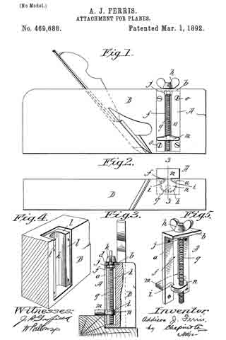
In the accompanying drawings the present improvements are fully illustrated, Figure 1 being a side view of a plane with the gage applied thereon. Fig. 2 is a plan of the bottom of the plane and of the gage, while Fig. 3 is an end view and partial vertical section of the plane and gage, taken on line 3 3, Fig. 2, said parts being shown as in working relation to a rabbeted piece of stock as used fora door or window casing. Fig. 4 is a perspective view of a portion of the plane-stock, showing the same as recessed for the reception of the gage attachment; and Fig. 5 is a perspective view of the gage attachment removed from the plane.

In the drawings, A represents the gage attachment, which, as specially illustrated, consists of a carrier-plate a, provided at its upper end with an angularly-extended portion b, vertically bored, as at d, and said carrier-plate is vertically slotted, as at f which slot is open to the bottom of the plate. The vertical screw g passes freely through the said bore or perforation d and lies alongside of and within the said carrier-plate and is prevented against endwise movement relative to the plate by the fixed thumb piece or head h, above the part b and the collar or nut j below the same.

m represents the gage, which is necked or formed notched intermediately of its opposing edges, as at i, so that the middle of the gage part may be entered in the slot between the side portions of the carrier-plate a, so that a lug or extension at of the gage mlies inside of the plate a and, being bored and tapped, has an engagement with the screw.

It will be seen that, due to the construction of the parts substantially as above set forth, the gage-block has a movable and sliding engagement with relation to the edges of the slot forming the guideway therefor.

The plane-stock B is in its side recessed, as at k, said recess extending from a short distance from the bottom face of the plane-stock to the top thereof, and the said recess at its borders and at the top is provided with the rabbets or rests l l, so that the carrier-plate a may be let within and disposed flush with the sides and top of the stock, nothing projecting outwardly beyond the stock in any direction except the gage proper m and the operating thumb-head. The plate is secured to the plane-stock by the screws o o. On desiring to adjust the gage m so that it will be brought and firmly held on the side of the plane-stock at a greater or less distance from the bottom face of the plane, such may readily and positively be effected by simply turning the screw by its head more or less in the one or the other direction to accord with the depth of the rabbet in the material which is to be finished up.

I therefore claim —

1. The combination, with the plane-stock having the recess in its side, of the carrier-plate a, with the longitudinal slot f and provided with the angularly-extended member b, with the aperture d, the gage m, having the neck guided by the edges of said slotway and provided with the lug n, and the screw g, passed freely through said aperture d and, while freely rotatable, held against endwise movement and having a screw engagement with said lug, all substantially as and for the purposes set forth.

2. An attachment for planes, consisting of the carrier-plate a, having the slot f extending longitudinally from one end thereof and having the angular portion b, with the aperture d, the block having the notched edges i, which have a movable and sliding engagement with the borders of said slot, and said block comprising the gage m and the lug n, which latter has a screw-opening, and the screw g, loosely passed through the aperture h and provided with the thumb-head h and the collar j and having a screw engagement with the said lug n, substantially as deserihed, for the purpose set forth.

ADDISON J. FERRIS.

Witnesses:
WM. S. BELLOWS,
G. M. CHAMBERLAIN.