No. 972,645 – Plane (Charles B. Rice) (1910)

[paiddownloads id=”674″]972645


UNITED STATES PATENT OFFICE.

_________________

CHARLES B. RICE, OF WASHINGTON, DISTRICT OF COLUMBIA.

PLANE.

_________________

972,645. Specification of Letters Patent. Patented Oct. 11, 1910.
Application filed April 28, 1910. Serial No. 558,164.

_________________

To all whom it may concern:

Be it known that I, CHARLES B. RICE, a cltizen of the United States, residing at Washington, in the District of Columbia, have invented a, new and useful Plane, of which the following is a specification.

This invention relates to planes of the type which are employed for grooving purposes, although the tool of the present invention is susceptible of other uses if desired.

The object of the invention is to provide a strong simple, durable and inexpensive grooving tool which can be used in a variety of positions and for a large number of useful operations and which can be easily and quickly adjusted to meet the requirements of different kinds of work, such for example as the grooving of doors and door frames for the purpose of securing the door locks and fittings in position.

With the foregoing and other objects in view which will appear as the description proceeds, the invention resides in the combination and arrangement of parts and in the details of construction hereinafter described and claimed, it being understood that changes in the precise embodiment of invention herein disclosed can be made within the scope of the claims without departing from the spirit of the invention.

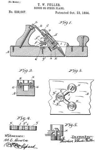
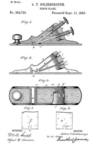
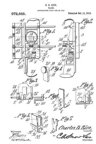
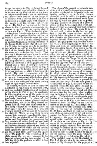
In the accompanying drawing forming part of this specification:– Figure 1 is a plan view of a grooving tool constructed in accordance with the invention. Fig. 2 is a side elevation thereof. Fig. 3 is a transverse section on the line 3–3 of Fig. 1. Fig. 4 is a similar section on the line 4–4 of Fig. 1. Fig. 5 is a detail perspective view showing a modified construction of bit post. Fig. 6 is a detail perspective view of one of the improved bits. Fig. 7 is a view similar to Fig. 6 showing another form of the improved bit. Fig. 8 is a perspective view of the clamping plate.

Like reference numerals indicate corresponding parts in the different figures of the drawings.

The reference numeral 1 indicates a base plate the lower surface 2 of which, as shown in Fig. 2, comprises a bearing surface which fits against the material to be operated upon, the bit 3 being caused to project beyond the bearing surface 2 through the opening 4 formed in the base 1. The base plate 1, at the forward end thereof, is provided with an upwardly extending curved handle or grip 5.

The bit 3 preferably is of the form indicated in Fig. 6. That is to say the bit is formed with a shank or plate 6 with which is adjustably connected the shank or plate 7 of a gage member 8 which determines the distance which the cutting tool 3 shall penetrate into the surface which is being operated upon. The gage 8 preferably consists of a tongue which projects in an oposite direction to the cutting edge of the tool 3. The preferred means of adjustably connecting the shank 7 with the shank 6, consists of a, screw 9 which projects through a slot 10 formed in the plate 7, said slot having an enlargement 11 at one end thereof to permit the initial introduction of the screw 9.

The means for securing the bit or cutting tool 3 in position within the opening 4 in the base plate, preferably consists of a post or standard 14 which, as shown in Fig 3, rises from the face of the base plate 1 adjacent the rear end of the opening 4, said post 14 being extended at its lower end to form the lateral shoulders 15 and the transversely extending flange 16. The shank 7 of the bit gage, and the shank 6 of the bit are fitted flat against the post 14 on the side thereof next to the openings 4 with the cutting edge of the tool projecting through said opening. A rectangular loop member 17 is then fitted downward over the post 14 so as to surround the bit shank 6 and plate 7, said loop member 17 resting at its lower end upon the shoulders 15 as shown in Fig. 5. A plate 18 is then fitted against the rear face of the post 14 between said post and the loop member 17. The plate 18, as shown in Fig. 8, is thickened adjacent its upper end as indicated at 19 and a set screw 20 is threaded through said thickened portion 19. By tightening the set screw 20 the point thereof projects against the rear face of the post 17 and the lower portion of the plate 18 serves to draw the loop member 17 tightly around the bit shank 6 whereby to bind the same firmly in any position to which it has been adjusted on the front face of the post 14.

For the purpose of providing a second bearing surface 25 which is arranged at a right angle to the bearing surface 2 and has an bit 3 projecting therefrom, the base plate 1 is formed or provided along one side thereof with an upstanding flange 26, said flange, as shown in Fig. 2, being formed with an inclined edge 26 which causes it to be narrow at the forward end of the stock of the plane and broad at the rear end thereof. The extreme rear end of the flange 26 is provided with a curved handle 28 which is disposed at a right angle with respect to the handle 5 at the forward end of the stock. The bit 3 on the bearing face 25, as shown in Fig. 1, projects in an opposite direction to the bit 3 on the bearing plate 2 as shown in Fig. 2. When the bearing plate 5 is employed therefore the stock is manipulated in the opposite direction to that in which it is moved when the other bit is being used. The bit 3 on the bearing surface 25 projects through an opening 30 formed in the flange 26, the upper edge of said opening 30 being inclined so as to be in parallelism with the edge 27 of the flange 26. The bit 3 of the bearing face 25 is mounted in the same way as the bearing face 2. That is to say it is mounted upon a post 14 which is provided with shoulders 15 and an enlarged flange 16 connected with the flange 26, a loop member 17 being fitted around the bit 2 and the shank 7 of the gage member 8 thereof and a plate 18 having a thickened end 19 and set screw 20 as shown in Fig. 8 being employed to tighten the bit and hold it in any position to which it has been adjusted. The post 14 connected with the flange 26 of course extends at a right angle to the post 14 connected with the base plate 1. This is necessitated by the fact that the two bits 3 are arranged with their cutting edges at right angles to each other.

If desired, the plate 18 and set screw 20 illustrated in Fig. 8 may be dispensed with, and the modified construction of clamping device shown in Fig. 5 may be employed. In this clamping device all the parts except the plate 18 and screw 20 are the same as previously described. In place of the clamping plate 18 a pair of plates 35 and 36 are employed, said plates being riveted together at their lower ends as indicated at 37 and being adapted to be forced apart at their upper ends by means of a lever 38 which is pivoted at 39 on ears 40 formed on the plate 35. When the lever 38 is thrown upward into inoperative position, the upper ends of the two plates 35 and 36 spring together and thus release the pressure on the loop members 17 so that the bit can be adjusted upward or downward if desired. When the bit has been properly adjusted, the lever 38 is thrown downward so that the end thereof bears against the plate 36 and forces the upper end of said plate away from the upper end of the plate 35. The separation of the plate causes the necessary pressure to be wrought to bear on the loop member 17 to hold the bit in the position to which it has been adjusted.

The plane of the resent invention is provided with a laterally disposed gage member 40 which is adapted to cooperate with the bearing surface 2 in performing certain classes of work in which the groove to be formed is located some distance away from the edge by which the plane is to be guided. The gage member 40 consists of a plate as shown in Fig. 3, the upper and lower surfaces of which are parallel with the bearing surface 2 of the plane. The plate 40 is so disposed with relation to the bearing surface 2 that the upper surface thereof is slightly below the plane of the bearing surface 2 so that the plate 40 can if desired be adjusted inward beneath the bearing surface 2. The gage plate 40 is provided at one end with a depending flange 41 and at the other end with an upstanding flange 42. The upstanding flange 42, as shown in Fig. 1 is provided with four threaded openings 43–43 and 44–44. Connected with either the set of perforations 43–43 or 44–44 is a pair of supporting rods 45 which extend through the flange 26 of the base plate 1 and through a flange 47 formed along the opposite edge of the base plate 1 from the flange 26. The rods 45 extent loosely through the flange 47 and are adapted to be locked in any position to which they have been adjusted by means of set screws 48 which extend downward through the flange 47 and are adapted to engage the rods 45. By loosening the set screws 48 the gage member 40 can be adjusted a greater or lesser distance away from the base plate 1. As indicated in Fig. 3, the plate 40 can be adjusted toward the base plate 1 to such an extent that the depending flange 41 will lie beneath the bearing surface 2 and will thus act as a gage for the cutter when working close to the edge by which the plane is being guided. If it be desired to arrange the gage member 40 on the opposite side of the device from that shown in Fig. 1, the rods 45 are unscrewed from the flange 42 and are reversed in the flange 47. The flange 42 is then connected with the threaded ends of the rods 45, the pair of threaded openings 43–43 being employed so that the forward ends of the gage member 40 will not project beyond the forward end of the base plate 1. Moreover, the gage plate 40 can be reversed while remaining on the same side of the plane as that shown in Fig. 1. By means of this reversal the plate 40 can be caused to project outward with relation to the flange 42 instead of inward toward the base plate 1 as shown in Fig. 3. It will also be obvious that the gage member 40 can be entirely removed from the plane whenever desired by simply withdrawing the rod 45.

The modified form of bit illustrated in Fig. 7 of the drawing is the same as that shown in Fig. 6 except that the gage plate instead of being formed at the lower end thereof with a tongue 8, is provided with a pair of downwardly extending cutters or points 50, which serve to cut the edges of the groove a little deeper than the flat bit 3 is adapted to cut the same. In this manner the cutter 50 serves to produce a cleanly defined groove in the operation, for example, of grooving the end of a door to receive the door lock or fitting.

The tool of the present invention is strong, simple, durable and comparatively inexpensive in construction as well as thoroughly efficient and practical in operation.

What is claimed as new is :–

1. A plane having a plurality of bearing surfaces one having a handle at one end and the other having a handle at the other end, said handles being angularly disposed with relation to each other, and a bit on each of said bearing surfaces having its cutting edge projected in the direction of the handle of said bearing surface.

2. A plane having a pair of bearing surfaces one of said surfaces being wider at one end than the other and having a handle at the wide end thereof and the other of said surfaces having a handle at the opposite end.

3. A plane having a bearing surface formed with an opening, a post adjacent said opening, shoulders adjacent the lower end of said post, a loop member surrounding said post and resting against said shoulders, a bit having a shank arranged between said posts and said loop on one side, and an adjustable member arranged between the other side of said post and said loop member for tightening the same on said bit.

4. A plane having a bit provided on the rear face thereof with an adjustable gage.

5. A plane having a bit provided with a cutting edge projecting in one direction, and a gage plate connected with said bit and having a gage tongue projecting in the opposite direction froin the cutting edge of the bit.

6. As a new article of manufacture, a plane bit having a cutting edge and a shank, and a gage plate adjustably connected with said shank for regulating the depth of the cut of said bit.

In testimony that I claim the foregoing as my own, I have hereto afhxed my signature in the presence of two witnesses.

CHARLES B. RICE.

Witnesses:
JAMES W. CROSS,
SAMUEL M. HOWELL.

No. 528,087 – Bench Or Other Plane (Theodore W. Fuller) (1894)

[paiddownloads id=”509″]528087


UNITED STATES PATENT OFFICE.

_________________

THEODORE W. FULLER, OF WASHINGTON, DISTRICT OF COLUMBIA.

BENCH OR OTHER PLANE.

_________________

SPECIFICATION forming part of Letters Patent No. 528,087, dated October 23, 1894.
Application filed October 4, 1893. Serial No. 437,138. (No model.)

_________________

To all whom it may concern:

Be it known that I, THEODORE WHISTON FULLER, of Washington city, in the District of Columbia, have invented certain new and useful Improvements in Bench or other Planes; and I do hereby declare that the following is a full, clear, and exact description of the invention, which will enable others skilled in the art to which it appertains to make and use the same, reference being had to the accompanying drawings, and to letters of reference marked thereon, which form a part of this specification.

My invention is an improvement on that class of bench and other planes for carpentering or wood-working, which have adjustable devices for holding the plane-iron or knife; such for instance as that patented to L. Bailey, No. 67,398, dated December 24, 1867; and it has for its object, not only to prevent the getting loose of certain parts but also to prevent the straining and wearing away of that part of the wood into which these devices are fastened, and which after a while render the plane entirely useless.

By my improvements the parts which support the plane-iron are held with it firmly to the adjusted position.

Heretofore the screws which were intended to hold the adjusting devices to the wooden body of the plane, were screwed directly into such wood. When such plane is in use the least jar knocks the cutter or plane-iron out of place. The strain and thrust come all upon these wood screws, tending constantly to loosen them by disintegrating the fibers of the wood and enlarging the screw hole until presently all possibility of a firm, fixed hold is gone, and the plane has to be replaced by a new one. This involves not only great annoyance, imperfect work in planing and frequent ineffectual efforts to satisfactorily hold the cutter to its adjusted working position, but also wastes much of the workman’s valuable time. I have therefore invented a simple, cheap, but most effective means for avoiding these difliculties, and whereby the tendency of the parts to loosen, weaken, or get out of order, are reduced to the minimum or entirely avoided.

In the drawings: Figure 1 shows in longitudinal section enough of a plane of the Bailey class as now found in the market, to illustrate my invention as applied thereto; Fig. 2, a cross-section in the line x x of Fig. 1, the cutter and its fastening plate being removed, the bolts being shown in full; Fig. 3, a plan of the two-armed metallic screw-held plate, having at the end of each arm a threaded hole for a machine-thread screw-bolt and at its angle end an unthreaded counter sunk hole for a wood-screw; Fig. 4, a front view or elevation of the same, and Fig. 5 is a detail, showing one of the machine-thread bolts in place in the plate.

A indicates the body of the plane; B, the plane-iron or cutter; C, the plate lying on and above the same; D, the cam-lever, and d’ its spring, for tightening this plate on the cutter; E, the lever supporting plate; F, the forked lever fulcrumed on this plate, and f’ the screw, and f2 the nut, for moving such lever to adjust the plane-iron longitudinally; L, the lever for adjusting said iron to insure the parallelism of the cutting edge with the bottom of the plane stock. These parts being well known, need not be more particularly described.

Instead of securing directly to the wood the plate E, which carries the forked lever and its adjusting screw, and which practice has been found so disastrous when and after its wood screws get loose, I make a stout specially-shaped two-armed plate G, the arms meeting at nearly a right angle, the plate being about three-eighths of an inch in thickness. The two ends of these arms have each also a hole g’ which is closely threaded to receive a machine-thread screw-bolt H; and at its angled end, it has a counter-sunk hole g2 to receive a wood screw g3. This plate I insert in a correspondingly shaped cavity made in the wood in the top of the plane a little back of the throat, so as to be tlush with it, and I secure it in place by the wood-screw in hole g2. The circular ends in which are threaded holes g’ serve like nuts, but being connected by the parts or webs i, j, to the circular portion g4, and all parts of the plate G being thus integral, this solid sunken plate when in place is practically immovable either forward or backward against any jar or blow, and against any and all back-thrust when using the plane; and even before inserting the screw bolts H. When the bolts H are inserted through the usual holes in plate E, their threaded ends engage respectively with the threaded holes g’ and hold the plate almost as firmly as if it were imbedded in a rock, or as if the plane stock were all of iron. It will now be seen that there can be no disintegration or wearing away of any screw-hole in the wood, for the plate is immovable relatively to the wood; the bolts H do not engage with any wood at all, and that all the thrusts are received and distributed against the entire rear wall of the cavity in which plate G is sunken; and in addition to this, this plate is fastened by its rear screw in the hole g2.

The part g4 is designedly located far enough back to permit its screw g2 to be readily inserted and removed, and the whole plate occupies a space otherwise not utilized.

It will now be seen that my improvement can be applied to any existing new, or old, or otherwise useless plane of the Bailey or similar class; that with an ordinary brace and bit, chisel and screw-driver any one can apply the plate G in a short time; that by reason of this thick threaded plate and its fine machine thread bolt, the plate E and the parts supported thereon can not only be tightened more firmly than by the means heretofore used, and held more permanently, and therefore needing less frequent adjustment, but the planes will wear and be useful for a great while longer.

My improvement is applicable to a great variety of planes, especially the jack-plane, fore-plane, or jointer and smoothing plane.

I claim —

1. In combination with a plane stock or body, a metal plate inserted in the top of the same back from the edge of the throat so as to be in closed both front and rear by the stock, the cutter supporting plate, and means whereby the same may be removably secured to said inserted plate, all as and for the purposes set forth.

2. In combination with a plane stock or body, a metal plate inserted in the top of the same back from the edge of the throat so as to be inclosed both front and rear by the stock, the cutter supporting plate, and means whereby the same may be removably secured to said inserted plate, and means whereby the inserted plate may be secured to the plane stock, all as and for the purposes set forth.

3. In combination with a plane stock or body, a metal plate inserted in the top of the same back from the edge of the throat so as to be inclosed both front and rear by the stock, and having screw threaded sockets in the same, the cutter supporting plate, and screws or bolts passing through holes in said plate into the threaded sockets of the inserted plate, to removably secure the same together, all as and for the purposes set forth.

4. In combination with a plane stock or body, a forked or angular metal plate inserted in the top of the stock back from the edge of the throat so as to be inclosed both front and rear by the stock, the cutter supporting plate, and means whereby the same may be removably secured to said inserted plate, all as and for the purposes set forth.

THEODORE W. FULLER.

Witnesses:
H. S. SHEPARD,
JOHN J. HALSTED.

No. 293,864 – Bench-Plane (Arthur T. Goldsborough) (1884)

[paiddownloads id=”355″]293864


UNITED STATES PATENT OFFICE.

_________________

ARTHUR T. GOLDSBOROUGH, OF WASHINGTON, DISTRICT OF COLUMBIA.

BENCH-PLANE.

_________________

SPECIFICATION forming part of Letters Patent No. 293,864, dated February 19, 1884.
Application filed July 19, 1883. (No model.)

_________________

To all whom it may concern:

Be it known that I, ARTHUR T. GOLDSBOROUGH, a resident of the city of Wlashington and District of Columbia, have invented certain new and useful Improvements in Metallic Bench-Planes, of which the following is a specification.

The nature of this invention relates to improvements in metallic bench-planes; and it consists in certain novel details of construction and arrangement, the particulars of which will be hereinafter fully described.

In the accompanying drawings, Figure 1 is a longitudinal section, in elevation, of a plane illustrating my invention. Fig. 2 is a plan view of the stock and handle, a portion of the upper part being broken away. Fig. 3 is a section in elevation on the line 3 3 of Fig. 1. Fig. 4 is an inverted plan view on the line 4 4 of Fig. 1. Fig. 5 is a detail view of a portion of the bit and its adusting-screw.

Similar letters denote like parts.

A represents the stock, and B represents a bridge or portion connecting the sides, in which moves the main or adjusting screw C. The bridge in this case, being only apertured to carry the said screw and not slitted for the insertion of the bit, may be made smaller and thinner than heretofore, and yet be possessed of the requisite strength and rigidity. Under the bridge, and in close proximity thereto, are two small short cleats or studs, b b, and directly above the throat H is located another cleat or stud, b’, both sets being arranged in the same line with respect to the throat of the plane. The bit D is formed with a T-shaped slot at its upper end, and the adjusting-screw C is provided with a corresponding head,which is T- shaped in cross-section. When in position, the bit may be moved freely up and down between the cleats by means of the said screw. The bit is inserted from below through the throat of the plane, as shown in dotted lines, Fig. 1, and some means must be provided for allowing sufficient movement of the said bit for it to be placed over the head of its adjusting-screw. This may be accomplished in several ways — as, for instance, forming the bit of a width less than that of the stock between the upper and lower set of cleats, or making one of the upper sets of cleats removable, or by forming triangular recesses E in the stock, within which recesses the upper end of the bit can be raised out of the path of the main or adjusting screw sufficiently to allow it, when only partially inserted, to be placed over its head. The motion of the screw is then reversed and the bit drawn in between the upper set of cleats as far as maybe desired. I prefer the latter plan, as it allows the use of a somewhat wider bit in proportion to the thickness of the sides of the stock, unless, as in the first-mentioned method, they (the sides) be made very thin. The bit, having been inserted loosely, is secured in position as follows: At a point about midway between the bridge and throat, and attached to the inside of the sole ofthe stock, is located the supplemental bridge F, in which is mounted the set-screw G, which has a conical or wedge-like end, g. The said bridge and screw are preferably placed at such an angle that the point of the screw G will strike the inside of the sole and the under side of the bit at equal angles, so that the force exerted by it, when tightened so as to lock the previously-adjusted bit, will be evenly distributed between the parts with which it is in contact. The rear portion of the stock is provided with the inwardly-extending ribs L L, the inner sides of which being oblique, they form together an inverted-V-shaped groove or slot.

The handle I is preferably made of cast-iron. It is provided with the internal-screw-threaded boss J and set-screw i, and the foot I’, which has extending or spreading sides K K. When the foot of said handle is inserted endwise into the V-shaped groove and the set-screw tightened against the sole of the stock, the handle will be securely held. By loosening the said screw i, the handle can be readily removed, and the said screw is intended to be arranged for operation by hand or with a screw-driver, as most convenient.

Having described my invention, I claim —

1. A bench-plane having a single bit and a detachably-connected adjusting-screw arranged inline therewith, and adapted to move said bit longitudinally in its plane of adjustment, a stock provided with rigidly-fined inward projections arranged on parallel lines on each side thereof, between which the bit is held and moved, and means for locking the adjusted bit by forcing it obliquely upward against the projections of the stock, as set forth.

2. A bench-plane having a single bit, an adjusting-screw detachably connected thereto, a stock formed with spaces or recesses leading obliquely upward from the throat and adapted to allow the upper end of said bit to be moved at right angles to its plane of adjustment while being connected to its adjusting-screw, and a set-screw arranged to exert pressure below said bit and lock it in its adjusted position.

3. In a bench plane, a stock formed with a bridge connecting the sides thereof on the line of the cutting-bit, and adapted to support a screw for controlling the longitudinal adjustment thereof, and a supplementary bridge located below the bit and adapted to support a set-screw operating between the bit and the inner side of the sole, cleats projecting inwardly from the sides of said stock, between which said bit moves and is adjusted, and a recess or space between the lower and upper cleats, within which the bit may be moved at right angles to its plane of adjustment, as set forth.

4. The stock A, formed with bridges B and F, the cleats b and b’, and recesses E or equivalent, substantially as shown and described.

In testimony whereof I have hereunto subscribed my name this 19th day of July, A. D. 1883.

ARTHUR T. GOLDSBOROUGH.

Witnesses:
FRANKLAND JANNUS,
FRANK P. WHILE.

No. 293,863 – Bench-Plane (Arthur T. Goldsborough) (1884)

[paiddownloads id=”354″]293863


UNITED STATES PATENT OFFICE.

_________________

ARTHUR T. GOLDSBOROUGH, OF WASHINGTON, DISTRICT OF COLUMBIA.

BENCH-PLANE.

_________________

SPECIFICATION forming part of Letters Patent No. 293,863, dated February 19, 1884.
Application filed July 19, 1883. (No model.)

_________________

To all whom it may concern:

Be it known that I, ARTHUR T. GOLDSBOROUGH, a resident of the city of Washington and District of Columbia, have invented certain new and useful Improvements in Metallic Bench-Planes, of which the following is a specification.

The nature of this invention relates to improvements in construction and arrangement of metallic bench-planes, the object of which is to reduce the number of working parts, and by promoting extreme simplicity of form to reduce the weight, cost, and liability to disarrangement of the several elements of which the tool is composed.

It consists in forming the stock in which the bit and its adjusting-screw are mounted with guiding and retaining cleats arranged in the same line as that of the bit, and between which it moves, and also with a projection near the throat on a somewhat higher line, and over which the bit is forced by its adjusting-screw when being brought to the cutting-point, which operation springs it slightly out of line, securely locking it against the several projections mentioned and hereinafter more fully described.

In the accompanying drawings, Figure 1 is a longitudinal section in elevation of a plane, illustrating my invention. Fig. 2 is a plan view of the stock, a portion thereof being broken away to show the cleats and projection or deflector. Fig. 3 is an inverted plan view on line 3 3 of Fig. 1. Fig. 4 is a detail view of parts of the bit and its adjusting-screw.

Similar letters denote like parts.

A represents the stock, which may be of metal, wood, or any other suitable material, but is preferably made of cast-iron.

B is the bridge, formed integral with the stock, and, being at the extremity of the path of the bit, it supports the adjusting-screw C, and also unites the two sides of the stock. The bridge is provided with a slit, b, through which the bit D is inserted and withdrawn; and it also has the threaded aperture b’, which carries the adjusting-screw G. The bit D is formed with a T – shaped slot at its upper end, and the screw C has a corresponding terminal, c, which is T- shaped in cross-section, so that the screw and bit are, when associated together, at all times detachably connected.

E is the throat, the rear interior edge of which is thickened or raised, so as to form the projection or deflector F.

G is a cleat, preferably forming an extension of the material of the stock, and it extends from the under side of the bridge to the deflector, terminating below the highest part thereof, and serving as a guide to direct the course of the bit when being inserted, so that the cutting-edge shall not come in contact with the deflector, but only the beveled under side of the bit.

G’ is a cleat extending about one-third the distance from the under side of the said bridge toward the throat, and parallel with the other cleat, G, with sufficient space between the two to allow the bit to pass freely up and down.

The operation of my device is as follows: The bit is placed in the slot d and moves freely down between the cleats until its beveled under side reaches and rests upon the deflector F, when its downward passage will be arrested. The screw C, having been connected to the bit when it was inserted, is now turned and the bit forced downward. Being held between both cleats at its upper portion only, the edect of this will be to spring the bit forward and obliquely upward, to enable it to pass over the deflector until its edge reaches the operative point, when the said bit will be tightly held between the highest point of the deflector and the short upper cleat, G’.

It will be readily seen that the deflecting device may consist of short cleats or projections attached to the side of the stock, near instead of at the throat of the plane, and they may also be placed above as well as below the bit, if found desirable.

Having described my invention, I claim —

1. A bench-plane having a single bit, and means for moving the same longitudinally, and a stock provided with fixed projections arranged in the path of the cutting-bit, but on different lines, between which projections the bit is held when forced to its operative point, as set forth.

2. A bench-plane having a single bit and detachably-connected adjusting-screw, and a stock formed with cleats, between which said bit. moves freely, and a deflector at or near the throat, over which the bit is forced to its operative point by its adjusting-screw, and between which deflector and cleats it is securely held, substantially as set forth.

3. In a beneh-plane, the stock A, formed with a guiding-cleat extending from the point of insertion of the bit to and terminating at a deflector or raised portion at or near the throat, and a cleat arranged above and parallel to and only a portion of the length of the said guiding-cleat, between which short cleat and the defleetor a cutting-bit may be securely held.

4. In a bench-plane, the combination, with the stock A, provided with slotted and screw-threaded bridge B, uniting the sides thereof, cleats G and G’, extending inward from the sides of the slot, and deflector or projection F, at or near the throat of the plane, of the bit D and detachable adjusting-screw C, all constructed and operating substantially as shown and described.

In testimony whereof I have hereunto subscribed my name this 19th day of July, A. D. 1883.

ARTHUR T. GOLDSBOROUGH.

Witnesses:
FRANKLAND JANNUS,
FRANK P. WHITE.

No. 284,732 – Bench-Plane (Arthur T. Goldsborough) (1883)

[paiddownloads id=”338″]284732


UNITED STATES PATENT OFFICE.

_________________

ARTHUR T. GOLDSBOROUGH, OF WASHINGTON, DISTRICT OF COLUMBIA.

BENCH-PLANE.

_________________

SPECIFICATION forming part of Letters Patent No. 284,732, dated September 11, 1883.
Application filed March 29, 1883. (No model.)

_________________

To all whom it may concern:

Be it known that I, ARTHUR T. GOLDSBOROUGH, a citizen of the United States, residing at Washington, in the District of Columbia, have invented certain new and useful Improvements in Metallic Bench-Planes; and I do declare the following to be a full, clear, and exact description of the invention, such as will enable others skilled in the art to which it appertains to make and use the same, reference being had to the accompanying drawings, and to the letters and figures of reference marked thereon, which form a part of this specification.

My invention relates to improvements in carpenters’ bench-planes; and it consists in providing a metallic plane of substantially the ordinary form, with two blades or bits especially adapted for use on coarse and fine work, respectively, but which may be used interchangeably; and, further, in so arranging said bits that all locking devices are dispensed with, the blades being arranged on convergent intersecting lines, so that the idle one, by being forced against its companion through the me-
dium of its adjusting-screw, acts to securely hold it in the desired position.

In the accompanying drawings, Figure 1 is a longitudinal sectional elevation, showing the general plan of construction and arrangement. Fig. 2 is a longitudinal sectional elevation of the stock or frame, the bits and adjusting-screws being removed. Fig. 3 is a plan view of the stock or holder, having a portion of the bridge and frame broken away to show the course of the interior grooves. Figs. 4 and 5 are detail views of the bits, showing the preferred mode of connecting the adjusting-screws thereto.

Similar letters denote like parts.

A represents the stock or frame, which is in many respects similar to those now in use.

G is a cross-piece or bridge, preferably formed integral with the remainder of the frame, and it is slitted and apertured as shown. The slits g g’ form entrances to grooves h h’, formed in the body of the stock, which grooves lead from the said slits and converge at the throat E, intersecting a short distance above that point. The circular apertures i i’ are internally screw-threaded, and lie in the same plane as the slits and grooves.

The bits B B’ are of ordinary shape and bevel, and are formed with spherical or T-shaped slots F at their upper ends.

The screws C C’ are provided with milled heads, and with spherical or T-shaped extensions b b’ at their inner ends, which register with the slots F. The screws C C’ are to be used in the apertures i i’ interchangeably, and are consequently of the same diameters.

The bits are placed in their respective slots, and the. heads b b’ in the slots F, when by turning the screws the bits are forced down until their converging ends meet, or until the heel of the bevel of one bit rests against the under or upper side of the bit, below or above it, as the case may be, when they will be securely locked each by the other. The lower bit having its beveled side up, and the upper one its beveled side down, it will be seen that the angle of contact between the bits is such that the cutting-edges never interfere, the bits touching only with the heel of one against the flat surface of the other. It is intended to use the upper bit for coarse work and the lower or reversed one for finishing.

The screw C is here shown longer than the one C’. Being interchangeable, it is preferred to exchange them when reversing the position and function of the bits in order to have them project about an equal distance from the bridge.

It will be found convenient to provide a spare screw of extra length for use when either of the bits becomes very much shortened. The same screw may be also used to lock the upper bit if it should be found desirable to use one bit only, the end of the screw acting as a wedge, and resting against the under side of the bit and the upper side of the interior of the stock.

By means of an aperture, D, any convenient instrument can be inserted to force the bits from one side to the other, they being allowed the ordinary amount of lateral movement, and it also allows the position and relation of the locking to that of the cutting blade to be observed. For planes of larger sizes a rear handle of any of the well-known forms will be added.

Having described my invention, I claim —

1. A bench-plane having a pair of blades or bits permanently arranged therein on convergent lines, said lines intersecting and crossing at a point above a common throat, substantially as set forth.

2. A bench-plane having a pair of cutting blades or bits arranged on convergent intersecting lines, a pair of interchangeable adjusting-screws detachably secured thereto, and suitable stock or frame, substantially as set forth.

3. In a bench-plane, a stock or frame formed with a pair of grooves intersecting at a point above the throat and diverging therefrom, and a bridge or brace forming part thereof, and slitted to form continuatious of said grooves, and adapted to allow the insertion and adjustment of the cutting blades or bits and controlling device, substantially as described.

4. A bench-plane consisting, essentially, of the combination of a stock or frame formed with a pair of grooves intersecting above the throat and diverging therefrom, and a bridge slitted to form continuatious of said grooves, a pair of cutting blades or bits adapted to be moved in convergent intersecting lines therein, and adjusting-screws detachably secured thereto, and having bearings in said bridge, whereby the bits may be used independently or as cutters and locking devices, respectively, substantially as set forth.

5. As an article of manufacture, a bench-plane having a pair of cutting blades or bits arranged on convergent intersecting lines, said bits being adapted for use as cutting and locking devices, respectively and interchangeably, a pair of interchangeable adjusting-screws detachably secured to said bits, and a suitably grooved and apertured stock or frame, substantially as set forth.

6. A plane stock or frame having the lateral apertures D located at the intersection of the cutting and locking blades, as set forth.

7. The combination, with stock A, formed with grooves h h’ and throat E, and the slitted and apertured bridge G, of the bits B B’, and adjusting-screws C C’, substantially as shown and described.

In testimony whereof I affix my signature in presence of two witnesses.

ARTHUR T. GOLDSBOROUGH.

Witnesses:
JOHN H. DEWANDELAER,
FRANKLAND JANNUS.

No. 148,090 – Improvement In Bench-Planes (Quartus Rice) (1874)

[paiddownloads id=”226″]148090


UNITED STATES PATENT OFFICE.

_________________

QUARTUS RICE, OF WASHINGTON, DISTRICT OF COLUMBIA.

IMPROVEMENT IN BENCH-PLANES.

_________________

Specification forming part of Letters Patent No. 148,090, dated March 3, 1874; application filed August 20, 1873.

_________________

To all whom it may concern:

Be it known that I, QUARTUS RICE, of Washington, District of Columbia, have invented an Improvement in Bench-Planes, of which the following is a specification:

Figure 1 is a vertical longitudinal section of a carpenter’s or wood-worker’s bench-plane. Fig. 2 is a plan view of the same.

The nature of this invention consists, first, in the combination of an oil-vessel with the plane, to be operated automatically by the working of the plane; and, secondly, in a presser and cap in one device, constructed and operated as hereinafter more particularly described.

A is a vessel to hold oil. The oil-vessel A has two covers, represented, respectively, by the letters d and e. d is of rigid material. e is elastic, and capable of vibration. f is an iron strap, to which the handle of the plane is fastened, and which is also made fast to the plane at g, and is so constructed that the end y has a slight vibration by pressure on the handle m. b is a tube, through which oil is poured into the vessel A. It is also connected at c with the cover e, and made to slip freely through the cover d, and connect with the strap f at y, so that the vibration of the strap f is communicated to the cover e, and thus the vessel A is alternately contracted and enlarged, and, as the vessel keeps filled with air, the contraction forces the oil out through the aperture at h to the face of the plane, as desired. a is a stopple for the tube b. O is a presser, to hold the cutting-bit firmly in place, and also serves as a cap for the cutting-bit. P is a thumb-screw, for regulating the distance of the cap from the edge of the cutter, by which the frame F, carrying the presser-cap O, is turned upon its pivots o’ o’ in the sides of the plane, while the cap also moves upon the pivots o” o”, by which it is hung to the frame F, and is adjusted to the cutting-bit, so as to press firmly thereon, while the distance from the cutting-edge is also adjusted.

I am aware that there are pressers similar to this, but am not aware of any which act as cap and presser, and regulated in the manner herein described.

I claim as my invention —

1. An oil-vessel, in combination with carpenter’s or wood-worker’s bench~planes, so constructed, in connection with other parts of the plane, that by working the plane the oil will be forced to the face of the plane, substantially as and by the means described.

2. The presser-cap O, constructed as and for the purposes described.

QUARTUS RICE.

Witnesses:
THOMAS C. CONNOLLY,
CAROLINE A. DOLBEAR.

No. 3,355 – Cast Iron Plane Stock (William Foster) (1843)

[paiddownloads id=”18″]3355


UNITED STATES PATENT OFFICE.

_________________

WILLIAM FOSTER, OF WASHINGTON, DISTRICT OF COLUMBIA.

CAST-IRON PLANE-STOCK

_________________

Specification of Letters Patent No. 3,355, dated November 24, 1843.

_________________

To all whom it may concern:

Be it known that I, WILLIAM FOSTER, of the city of Washington and District of Columbia, have invented a new and useful Improvement in Cast-Iron Plane-Stocks; and I do hereby declare that the following is a full, clear and exact description thereof; reference being had to the accompanying drawings, which form a part of this specification, in which —

Figure 1, is an isometrical view showing the under side of the plane, or face; Fig. 2, vertical section.

The nature of my invention consists in forming a recess in the face of the plane stock, into which an adjustable piece of soap stone, or other suitable material is inserted and regulated by a screw.

The face (a) of the plane stock is oblong and true, and of the usual form of wooden plane stocks, but only sufficiently thick for strength; from each side flanches (b) rise, while at the point where the plane iron is inserted is as high as a common wooden stock, from them they gradually taper off to each end. A slit (c) is cut across the face through which the plane iron projects, and just forward of this there is a recess (d) into which a piece of soap stone (e) or other suitable material or substance is put, the projection of which is regulated by a screw (f) above, this forces it out as it wears away. Grooves are cast on the sides of the plane stock, inside from the throat up to the top to hold the plane iron and wedge; behind them is a socket projecting up from the inside of the face to hold the handle, which is made from wood in the usual way ; before the recess (d) occasions the plane to run light and easy, thus rendering it the most efficient plane stock made for durability, economy and convenience. The recess (d) may be formed if desired before the socket (h) instead of behind as before explained and described.

Having thus fully described my cast iron plane stock, what I claim as new and desire to secure by Letters Patent is —

The recess (d) formed in front of the plane iron, or of the forward handle, in the face of the cast iron plane and filled with soap stone or other suitable material, which is regulated by a screw substantially in the manner, and for the purpose herein explained.

WILLIAM FOSTER.

Witnesses:
J. J. GREENOUGH,
L. CALDWELL.