
No. 306,693 – Molding-Plane (James R. Lawrence) (1884)

UNITED STATES PATENT OFFICE.
_________________
JAMES R. LAWRENCE, OF DURHAM, NORTH CAROLINA,
ASSIGNOR OF ONE-HALF TO W. T. BLACKWELL, OF SAME PLACE.
MOLDING-PLANE.
_________________
SPECIFICATION forming part of Letters Patent No. 306,693, dated October 14, 1884.
Application filed August 12, 1884. (No model.)
_________________
To all whom it may concern:
Be it known that I, JAMES R. LAWRENCE, a citizen of the United States, residing at Durham, in the county of Durham and State of North Carolina, have invented certain new and useful Improvements in Molding-Planes, of which the following is a specification.
My invention relates to a molding-plane for curved or circular work; and it consists in certain features hereinafter described and claimed.
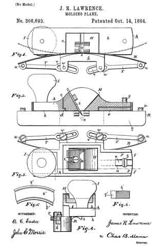
In the drawings hereto annexed, Figure 1 is a bottom view of the plane. Fig. 2 is a side view showing a longitudinal section. Fig. 3 is a top view of the plane. Fig. 4 is an end view of the same. Figs. 5 and 6 show a specimen of the curved molding.
The body A is made of cast metal and has a flat sole, b. Its central part comprises a box or recess, c, which has around the inner sides next to the fiat sole an inward-projecting flange, d. At the forward end the body has on top a straight rib, e, extending lengthwise, on each side of which is a straight depression or groove, f. A clamp-screw, g, enters the straight rib and serves to hold the bit-stock H to its place. A knob or other suitable handle, I, is attached to the rear end. Attached to the body at one side is a guide-holder, k, which projects below the sole. The bit-stock H occupies the box or recess c, and the bit l may have its cutter-edge shaped to produce any desired style of molding, a specimen of which is shown in Figs. 5 and 6. The lower edges of the bit-stock rest upon the inward-projecting flange d, and the forward end has at central slit, n, which receives the rib e, and the bifurcations p occupy the straight grooves f each side of the rib. By this construction and arrangement of parts the clamp-screw g may be tightened on top of the bifurcations p, and thereby hold the bit-stock firmly to its seat. The flexible guide R is made, preferably, of a strip of steel thin enough to give it the desired flexible character, adapting it to be bent to suit the curvature of the work. The face q of this guide has position at a right angle to the sole b of the body, and while the latter, with the bit, sets upon the top b of the work to be planed (see Figs. 5 and 6) the guide bears against the curved edge q’. The guide-holder k is permanently attached to the plane-body at one side of the central box or recess. The flexible guide is rigidly secured to the holder k at its center s — that is, at a point midway of the ends of the guide. While the center of the guide is thus held immovable, the extremities may be pressed back or forth in either direction to any desired extent within certain limits, as shown and indicated in Fig. 1. A stay-brace, T, connects each end of the flexible guide with the body of the plane. These serve to hold the guide wherever it may be set — that is, either straight or curved. These stay-braces may have any construction that will enable them to be shifted so as to lengthen or shorten the connection, thereby to alter the adjustment of the flexible guide. In the present instance one end of the stay-braces is jointed at u to the flexible guide, and the other end of each brace has a slot, v. A set-screw, w, passes through the slot and enters the holder. When the set-screws are loosened, the slots allow the connections between the set-screws and the ends of the flexible guide to be lengthened or shortened, thereby causing the guide to be curved as desired. It will be seen that the plane will work in a straight line or in a circle, either inside or outside.
To set the guide for any desired work remove the bit-stock H, loosen the set-screws w, then place the plane-body on the work and press the flexible-guide up to the curve or circle and tighten the set-screws. Now replace the bit-stock and the plane is ready for the work. It will be seen that by this construction the cutting-bit may be set, then by removing the bit-stock and cutter the flexible guide may be readily adjusted to the work.
Having described my invention, I claim and desire to secure by Letters Patent of the United States —
1. A plane having a cast-metal body, A, provided with a central box or recess, c, a bit-stock, H, occupying the recess and having at its end a central slit, n, and bifurcations p, and a clamp-screw, g, in the body, and adapted to be tightened on top of the said bifurcations, as set forth.
2. A molding-plane having in combination a body, A, provided with a central box or recess, and a guide-holder, k, permanently attached at one side of said central box or recess and adapted to be readily removed therefrom, and a flexible adjustable guide secure to said holder, whereby the bit-stock and cutter may be removed to facilitate the adjustment of the flexible guide to the work, as set forth.
In testimony whereof I affix my signature in presence of two witnesses.
J. R. LAWRENCE.
Witnesses:
W. W. ELLINGTON,
S. W. CHAMBERLAIN.