No. 367,071 – Gage For Wood-Working Planes (Edward B. Shepardson) (1887)

UNITED STATES PATENT OFFICE.
_________________
EDWARD B. SHEPARDSON, OF GREENFIELD, MASSACHUSETTS.
GAGE FOR WOOD-WORKING PLANES.
_________________
SPECIFICATION forming part of Letters Patent No. 367,071, dated July 26, 1887.
Application filed April 6, 1887. Serial No. 233,912. (No model.)
_________________
To all whom it may concern:
Be it known that I, EDWARD B, SHEPARDSON, a citizen of the United States, residing at Greenfield, in the county of Franklin and State of Massachusetts, have invented certain new and useful Improvements in Gages for Wood-Working Planes; and I do hereby declare the following to be a full, clear, and exact description of the invention, such as will enable others skilled in the art to which it appertains to make and use the same.
This invention is an improvement in gages as attachments to woodworking planes; and it has for its object to provide an attachment to planes of hollow metal construction, one part of which is adjustable about an axis of motion to any required angle with reference to the bottom surface of the plane to which said gage is attached, so that a guide will be formed to fit against one surface of the material and slide against the same as the bottom of said plane rides over an edge of said material, cutting the same and forming an angle with reference to anotherside of said material greater or less than a right angle.
Mechanics who are in the habit of using wood-working tools are familiar with the difficulties encountered in beveling the edge of a board where the eye and feeling or judgment alone are depended upon in making the required angle. It is desirable, in view of such difficulties, that a good and simple device be provided, so that the operation of beveling may be only mechanical. Such devices have been invented, I am aware, as applicable to planes the stocks of which are of wood. My gage is intended to be applied to a plane the stock of which is of metal. My gage is formed, in the main, of two pieces of metal hinged together. One of said sections consists of a horizontal bar having at each of its two ends projections of T form, the bar, with its two ends, forming an H, as seen from the outside. Each of the T ends is bent inward nearly at right angles. The upper of these bent ends forms lugs for clamping-screws, and the lower of said bent portions is slotted and connected by a bracing-bar. The lower part of the gage is composed of a bar of U shape, the inner plane-surface of which is smooth, and the ends of said bar form tongues, which enter the slots in the upper portion of said gage where the two said parts are hinged together. Bifurcated pieces, forming clevises, project outward from the H -bar and the U -bar, and in these are pivoted or hinged screw-threaded nuts. A right-and-left screw provided with a thumb-piece on its center engages these nuts, and when operated increases or diminishes the angle between the two parts of the gage.
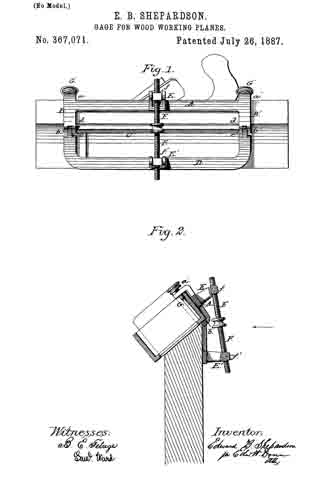
In my drawings, Figure 1 is an elevation of the gage as seen from the outside. Fig. 2 is a transverse vertical section of the same, showing the application of the gage to a plane and the relation of the latter to a piece of material being beveled.
Similar reference-letters indicate like parts in both of the figures.
Referring to the drawings, A is the horizontal bar of the upper portion of the gage, and B B’ are the T ends ofthe same, provided with bent portions a a’ b b’, the latter of which are connected by the strengthening-bar C.
d d’ are slots formed in the bent ends b b’, which receive the tongues e e’ of the lower portion of the gage.
D is the lower portion of the gage, formed as previously stated, the tongue ends of which are hinged in the slots of the T-pieces B B’. The long bar of the upper portion of the gage and the curved bar of the lower portion of the same have projecting from their centers outward bifurcated pieces or clevises E E’. In the outer ends of these clevises are pivoted swivel-nuts f f’, adapted to receive the right and left ends of the double screw F.
The bent T ends a a’ have screw-threaded openings to receive the screws G G’, the clamping ends of which latter may be threadless.
In applying this gage to a plane I place the bent portions a a’ on one of the side walls, with the long bar A resting against the outside of said wall and the clamping-screws — not yet driven down — against the inside of the same. The gage should be so placed upon the plane that one of the clamping-screws shall be in front of the handle and the other rearward of the same. When the screws are driven down to place, they impinge upon the bottom plate of the plane and draw the bent ends b b’ of the gage up against the bottom surface of said plane, and the gage is thus firmly held to place.
It may be observed that the interior angles between the T-pieces and portions a a’ are less than right angles, so that the screws when driven home find their places in the angle of the plane formed by the inner surface of the bottom and the inner surface of the said side wall. The gage being thus firmly secured to the plane, when the angle of the bevel to be made is determined the lower or U -shaped bar of the gage is moved about its axis by the right-and-left screw G G’ until the proper angle is formed. The gage is now applied with the plane to the piece of material to be planed in such a manner that the inner surface of the U-shaped bar rests against one side of said material and the bottom surface of the plane upon the edge of the same to be beveled.
The operator has only to keep the gage upon the guiding-surface of the material as he operates the plane to insure accurate work.
Having thus described my invention, whatl claim as new, and desire to secure by Letters Patent, is —
In a gage for use with wood-working planes, the combination, with the upper portion provided with clamping-screws, a swivel-nut, and jaws or bearings for the same, of the lower portion of said gage hinged to the said upper portion, provided with a swivel-nut and jaws or bearings for the same, and the right-and-left screw engaging said swivel-nuts to adjust the two portions, the one with reference to the other, as and for the purpose set forth.
In testimony whereof I affix my signature in presence of two witnesses.
EDWARD B. SHEPARDSON.
Witnesses:
JAMES S. GRINNELL,
FRANKLIN G. FESSENDEN.


