No. 864,101 – Plane (Edward S. Marks) (1907)

UNITED STATES PATENT OFFICE.
_________________
EDWARD S. MARKS, OF AUBURN, NEW YORK, ASSIGNOR TO OHIO TOOL COMPANY, OF AUBURN, NEW YORK, A CORPORATION OF NEW YORK.
PLANE.
_________________
864,101. Specification of Letters Patent. Patented Aug. 20, 1907.
Application filed March 7, 1907. Serial No. 361,030.
_________________
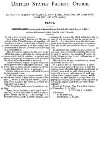
To all whom it may concern:
Be it known that I, EDWARD S. MARKS, a citizen of the United States, residing at Auburn, in the county of Cayuga and State of New York, have invented or discovered certain new and useful Improvements in Planes, of which the following is a specification, reference being had therein to the accompanying drawings.
This invention relates generally to bench planes and more particularly to the manner of seating the “frog”, or support for the bit or cutting iron, upon the sole or bottom of the plane. In planes of this character the frog is ordinarily made in a piece separate from the body or stock of the plane and bolted or otherwise secured thereto, and is adjustable longitudinally of the plane body in order to permit the effective size of the throat or opening in the sole of the plane to be varied. When, however, a frog of this character is adjusted to a position in which its forward or bit-supporting face lies in a plane in advance of the rear edge of the throat or opening in the sole, the lower end of the bit is left unsupported for a distance above its cutting edge equal to the thickness of the sole. In order to remedy this defect and to provide a support for the bit as near the cutting edge thereof as possible it has been proposed to provide a thinned down portion of the sole at the rear of the mouth or throat by cutting away the sole at its upper side at this point, and to provide the frog with a depending lip at its forward side which is received in the recess formed by cutting away the sole as above described, and which is adapted to support the bit at a point close to its cutting edge. It is necessary, however, in order to prevent rattling of the parts and to provide a firm support for the bit against the thrust of the plane, that the frog have a firm bearing upon the sole of the plane at a plurality of points and that it be firmly and tightly bolted or otherwise secured thereto. In the construction last referred to one of the supports of the frog upon the sole is provided by causing the depending lip on the frog to bear upon the thinned down portion of the sole at the rear of the throat. This is undesirable, since when the bolts which secure the frog to the sole are screwed down tightly the bearing of the lip of the frog upon the thinned down and therefore weakened portion of the sole tends to spring said thinned down portion out of the plane of the lower surface of the sole, thereby seriously impairing the efficiency of the plane.
One object, therefore, of my invention is to provide means for supporting a frog of the character above referred to in such a manner that the bit is supported at a point close to the cutting edge thereof while no tendency to warp any portion of the sole out of its proper plane is produced.
A further object of my invention is to dispense with the heavy raised frog seats which have been heretofore used in planes of this character, thereby simplifying the manufacture of these planes and reducing their weight.
A still further object of my invention is to improve certain details of construction in planes of this character, as will hereinafter appear.
To these ends my invention consists in certain constructions and combinations of parts hereinafter described and particularly pointed out in the claims.
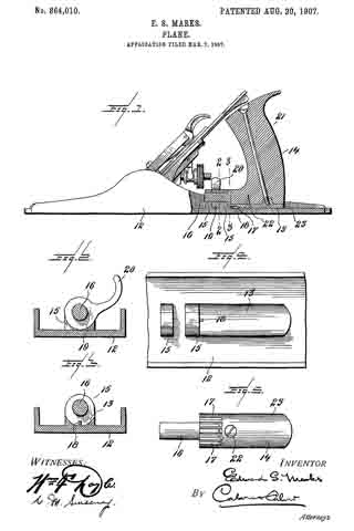
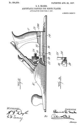
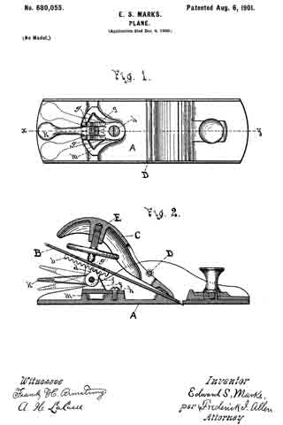
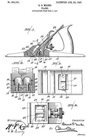
Referring to the drawings accompanying and forming part of this specification, Figure 1 is a side elevation, partly in section, of a plane made in accordance with my invention. Fig. 2 is a cross section of the plane stock and frog, taken substantially on the line 2–2, Fig. 1. Fig. 3 is a plan of a portion of the sole with the frog removed, showing the frog seat. Fig. 4 is a bottom plan view of the seating portion of the frog.
Like characters indicate like parts throughout the several views of the drawings.
12 indicates the stock or body of the plane, having a sole 13 provided with the usual throat or mouth 14, at the rear of which the sole is cut away at its upper side to provide a thinned down portion 15. Directly in the rear of said thinned down portion 15 is formed, preferably upon the sole of the plane itself, a single, continuous frog seat 16.
The frog seat 16 is adapted, alone, to support the frog, and to this end it is made of sufficient area to provide the necessary extended bearing surface to seat the frog firmly and to prevent any rocking movement thereof. The seat 16, as shown, lies wholly in a single plane substantially coincident with the upper surface of the sole, and, in the embodiment of my invention herein illustrated, is constructed in the form of a hollow rectangle, although it is obvious that many changes in the specific form of this seat might be made without departing from the spirit of my invention.
Located within and surrounded by the seat 16, and extending transversely of the sole of the plane, is a boss or rib 17. This rib is provided in order to furnish sufficient thickness of material to insure a secure engagement of the bolts 18, 18, which serve to clamp the frog 19 to its seat. To this end the boss or rib 17 is provided with threaded openings 20, for the reception of the attaching bolts 18. Preferably and as herein shown the rib 17 is provided with a transverse groove or notch 21 for the reception of a guiding or centering rib 22, on the frog 19. It will thus be seen that the boss or rib 17, provides means for engaging the attaching bolts 18, 18, and also means for guiding or preventing undue lateral movement of the frog 19, but in no other sense does the boss 17 support the frog, there being a slight clearance provided between the upper surface of the boss 17 and the opposite lower surface of the frog 19, and between the bottom of the groove 21 and the crest of the rib 22.
The frog 19 is provided with a depending lip 23, for supporting the bit 24 close to its cutting edge, and with a continuous seating portion 25, codperating with the seat 16. Surrounded by said seating portion 25 is a recess 26, for the reception of the boss 17 in the bottom of which recess is located the rib 22, and the slots 27, 27, for the passage of the attaching bolts 18, 18.
It will be noticed that a slight clearance, indicated by the numeral 28 in Fig. 1, is provided between the lower edge of the lip 23, and the thinned down portion 15 of the sole. These two parts are never allowed to come into engagement with one another, and all tendency to distort or warp this necessarily weak part of the sole is entirely prevented. The continuous frog seat 16 is oi sufficient extent to provide an absolutely firm bearing for the frog without any necessity for the frog to find an additional bearing on the thinned down portion 15 of the sole. Moreover my construction provides a wide seating area for the frog combined with a compactness of parts which is very desirable.
It will be further noticed that the frog is seated directly upon the sole, thus doing away with the heavy raised portions which have heretofore been considered necessary in order to provide the necessary bearings for the attaching screws of the frog, but which are difficult to cast satisfactorily, and which support the frog in an objectionably high position, or which have been omitted at the expense of the strength and durability of the plane. In my construction, however, the relatively small lug 17, which is not difficult to cast, provides sufficient thickness of metal to hold the attaching screws firmly, while the frog has a broad, flat, and desirably low support.
While I have shown and described one form in which my invention may be embodied, I wish it to be distinctly understood that I do not limit myself to the precise construction shown, it being obvious that many changes may be made therein without departing from the spirit of my invention.
Having thus described my invention I claim and desire to secure by Letters Patents —
1. In a plane, the combination with a sole having a frog seating surface lying in a single plane and a raised boss or rib provided with frog attaching means, of a frog having a plane seating surface adapted to cooperate with the seating surface on said sole, and cooperating means on said boss or rib and said frog for preventing relative lateral movement of said frog and sole.
2. In a plane, the combination with a sole having a single plane frog seating surface and a raised boss or rib provided with a groove, of a frog having a recess to receive said boss and a rib adapted to cooperate with said groove.
3. In a plane, the combination with a sole provided with a frog seating surface lying in a plane substantially coincident with the remainder of the upper surface of said sole and with a boss or rib rising above the plane of said frog seating surface, of a frog provided with a single seating surface adapted to coijperate with the seating surface on said sole and with a recess to receive said boss or rib, means cooporating with said boss or rib for attaching said frog to said frog seat, and coperating means on said boss or rib and said frog for preventing relative lateral movement of said frog and sole.
4. In a plane, the combination with a sole provided with a frog seating surface lying in a plane substantially coincident with the remainder of the upper surface of said sole and with a boss or rib rising above the plane of said frog seating surface, said boss or rib having a threaded aperture, of a frog provided with a single seating surface adapted to cooperate with the seating surface on said sole and with a recess to receive said boss or rib, a bolt cooperating with the aperture in said boss or rib for attaching said frog to said frog seat, and coiiperating means on said boss or rib and said frog for preventing relative lateral movement of said frog and sole.
5. In a plane, the combination with a frog having a depending lip, of a sole provided with a throat or mouth, a thinned down portion in the rear of said throat or mouth, a frog-seating surface lying in a plane substantially coincident with the remainder of the upper surface of said sole, and a boss or rib rising above the plane of said frog seating surface, means cooperating with said boss or rib for securely clamping said frog to said seat, said depending lip being out of contact with said thinned down portion, and coiiperating means on said boss or rib and said frog for preventing relative lateral movement of said frog and sole.
6. In a plane, the combination with a frog, of a sole having a throat or mouth. a frog seating surface in the rear of said mouth, and lying in a plane substantially coincident witli the remainder of the upper surface of said sole, and a boss or rib rising above the plane of said frog seating surface and provided with a frog-attaching means, and cooperating means on said boss or rib and said frog for preventing relative lateral movement of said frog and sole.
7. In a plane, the combination with a frog, of a sole having a plane frog seating surface and a raised boss or rib, and cooperating means on said boss or rib and said frog for preventing relative lateral movement of said frog and sole.
In testimony whereof I affix my signature, in presence of two witnesses.
EDWARD S. MARKS.
Witnesses:
JOHN W. BRAINARD,
RALPH R. KEELER.