No. 112,949 – Improvement In Molding-Planes (Ellis H. Morris) (1871)
United States Patent Office.
ELLIS H. MORRIS, OF CANTON, OHIO.
Letters Patent No. 112,949, dated March 21, 1871.
_________________
IMPROVEMENT IN MOLDING-PLANES.
_________________
The Schedule referred to in these Letters Patent and making part of the same.
_________________
To all whom it may concern:
Be it known that I, ELLIS H. MORRIS, of Canton, in the county of Stark and State of Ohio, have invented a new and valuable Improvement in Molding-Planes; and I do hereby declare that the following is a full, clear, and exact description ofthe construction and operation of the same, reference being had to the annexed drawing making a part of this specifcation and to the letters and figures of reference marked thereon.
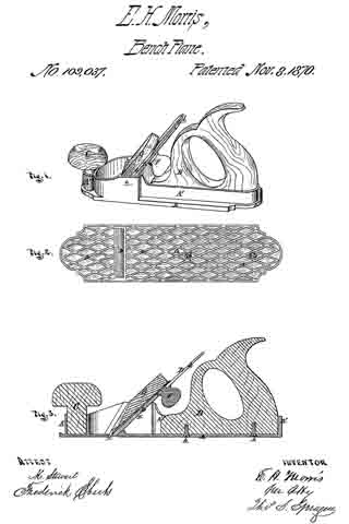
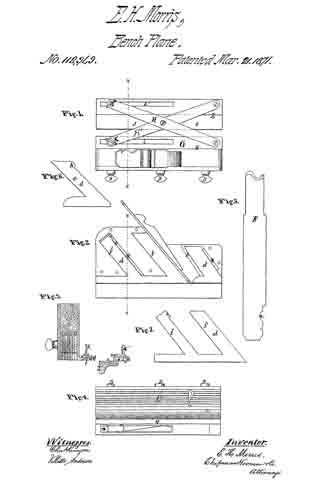
Figure 1 of the drawing is a top view of my plane;
Figure 2 is a side elevation, with the side plate removed;
Figure 3 is a vertical transverse section;
Figure 4 is a bottom view; and Figures 5, 6, and 7 are details.
My invention has relation to an improvement in planes; and It consists in providing a plane-stock with an adjustable face, capable of being molded or shaped to suit a plow-bit of any form; also, in attaching to the plane-stock an adjustable extension-gauge, designed to enable the bit to be run at any desired distance from the edge of a board or panel, as hereinafter described.
The letter A of the drawing designates my plane-stock, which may be similar in its external form to the ordinary plane-stocks in common use. The under side of the stock is channeled or excavated from side to side to receive the thin vertical sections which constitute the adjustable face of the stock.
B B represent elongated recesses or ways extending up into the body of the plane-stock, from the channel at the base, at an angle of forty-live degrees, or corresponding to the angle of the bit. These recesses serve to receive the offsets from the face-sections, presently to he described. Usually I make one of these recesses in front of the throat of the plane, and two in rear thereof.
C designates the adjustable face of my plane-stock. This is composed of two sets of thin vertical strips d, running in the direction of the length of the plane-stock. One set of these strips is situated in front ot the bit and the other is placed in rear, following the bit.
Each strip of the first set is provided with an offset or guiding-arm, e, which extends upward and backward at an angle of forty-five degrees, or parallel to the bit, into the recess B.
Each stern e is provided with a projection, h, at its upper forward corner, which is designed to engage with a stop, k, in the wall of the recess. The arm e is arranged to slide up and down in its recess, the distance to which it can descend being regulated by the position of the stop it and the projection h.
Each strip of the second or rear set is provided with two guiding-arms f f’, extending upward and rearward, parallel to the arm of the strip in front of the bit, which immediately precedes it.
The forward arm f’ of the rear strip is without a stop, and slides in a recess formed in the rear wall or the throat of the stock.
The rear arm f is similar to tue arm e ofthe forward strip, being provided with a projection, and arranged to engage with a stop in the wall of its recess which limits the descent of the strip. These stops k are placed in the recesses in such a position that they will allow the strips to descend as far as the lowest point of any one of the ordinary plow-bits in use.
These strips or sections d are usually made thin, in order that they may conform as closely as possible to the configuration of the edge of the bit. The face-edge of each strip is transversely rounded, or beveled on each side.
D D represent set-screws, passing through the wall of the plane-stock, and serving to secure the strips in their relative position to each other and to the bit after they have been properly adjusted and molded in form.
E represents my bit, which is provided with a means of shaping the adjustable face of the stock to suit its cutting-edge.
This consists of a notch or indentation, a, formed in its upper edge, and corresponding precisely in shape with the edge of the bit, with the exception that the general curve or profile is reversed and flatter.
The face-sections having been adjusted out to fill the mold the set-screws are tightened, and the strips thereby rigidly secured in position.
The bit and wedge are now inserted in the throat of the plane-stock, and, having been properly adjusted, the tool is ready for operation.
This stock, with its adjustable face, may be used with a stationary gauge, but usually I prefer to attach to it my extension-gauge, as follows:
At the base of the exterior wall of the stock, on the left or inner side, is formed a projecting ledge, G, which extends usually the entire length of the stock.
At the forward end a circular projection is raised, which serves as a bearing for the inner end of the extension-bar H.
A slot, l, traverses longitudinally the rear portion of the ledge G.
The under side of the ledge G is recessed at v v, on each side of the slot l, to receive the flanches of the nut n.
K represents a clamp-screw, by means of which the inner end of the extension-bar H’ is pivoted to the ledge G. The end of this clamp-screw passes through the slot l, and, engaging with the square nut iz, serves to hx the bar H’ in any desired position.
The bars H and H’ cross each other, and are pivoted together at about their middle portions by the pivot r. The outer end of the bar H is bent downward in order to bring it on a level with the outer end of the bar H’.
Z represents the movable gauge-bar. The upper and inner corner of this bar is recessed at s to receive the ledge G, thus permitting the face z’ of the gauge to be brought up close to the bit, when desirable.
The outer end of the bar H’ is pivotcd to the forward end of the gauge-bar Z.
The rear end of the gauge-bar Z is slotted at l’ to receive a clamp-screw, K’, which operates, in conjunction with a nut, n’, to secure the outer end of the bar H at any point of the slot.
The distance to which the gauge can be extended from the bit is regulated by the length of the cross-bars H H’ and the length ofthe slots l l. The gauge-bar, when adjusted at the proper distance from the bit, can be rigidly fixed in that position by means of the clamp-screws K K’.
A plane constructed in this manner is designed to subserve purposes of great importance to cabinet-makers and carpenters. To journeymen especially it will prove a great convenience in the saving that will ensue in transportation, one stock being sufficient for all the bits that they may employ. Carpenters, even of small means, can execute a great variety of moldings, limited only by the number of different bits which they may possess.
What I claim as my invention, and desire to secure by Letters Patent, is —
1. A plane-stock, having an adjustable face, capable of being varied in form to suit bits having differently-shaped cutting-edges, substantially as specified.
2. The combination, with a plane-stock provided with a slotted ledge, G, of the slotted gauge Z, cross-extension arms H H’, and clamps K K, substantially as specified.
3. The combination, with a plane-stock having an adjustable face, of a bit provided with a forming indentation, substantially as specified.
In testimony that I claim the above I have hereunto subscribed my name in the presence of two witnesses.
ELLIS H. MORRIS.
Witnesses:
L. W. JONES,
J. H. LIDDALL.