No. 6,226 – Plane Iron Adjustment (Emanuel W. Carpenter) (1849)

[paiddownloads id=”1″]6226


UNITED STATES PATENT OFFICE.

_________________

E. W. CARPENTER, OF LANCASTER, PENNSYLVANIA.

ADJUSTING THE POSITION OF PLANE-IRONS AND REGULATING THE THROATS OF PLANES.

_________________

Specification of Letters Patent No. 6,226, dated March 27, 1849.

_________________

To all whom it may concern:

Be it known that I, EMANUEL W. CARPENTER, of Lancaster city, in the county of Lancaster and State of Pennsylvania, have invented a new Improvement in the Regulation of the Mouths in Planes so as to Enlarge or Diminish the Same and for the Preservation of a Close Mouth in Planes; and I do hereby declare that the following is a full, clear, and exact description of the construction and operation of the same, reference being had to the annexed drawings, making a part of this specification.

The object contemplated by my improvement, is the regulation of the mouth in planes, so as to enlarge or diminish the same; and for the preservation of a close mouth in planes.

To enable others skilled in the art to make and use my invention, I will proceed to describe its construction and operation, as follows, viz.:

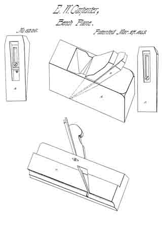
A is a bench plane with the improvement.
B represents the wedge or key, with a. longitudinal aperture, over which is a scutcheon, inlaid with a similar aperture but not so wide, leaving room for the head of the screw to rest upon, (or by a washer or plate, as shown in the key in the double bit) for the purpose of fastening the key to the upper part of the bed of the plane, under the bit, by means of which the mouth of the plane can with ease be tightened by gently driving the key downward, or with equal ease enlarged, by drawing back the same.

The improvement is applicable to all kinds of planes.

The wedge or key in the double-bit plane is similar to that in the single-bit, with the exception of the opening left below the longitudinal aperture to receive the head of the screw that fastens the cap to the bit. A washer or plate is here used instead of the scutcheon as in the single-bit, to show its application, but the scutcheon is equally applicable.

C, is the molding plane, with the improvement. The wedge or key in the molding plane, is shaped like the bit, but the key part somewhat longer, and tapered down to the face of the plane; the bed of which, is out to suit the bevel or shape of the key B. The screw is here inserted at the upper side of the plane, to keep the key B, permanent while setting the bit.

What as I claim as my invention, and desire to secure by Letters Patent is —

The regulation of the mouth in planes, so as to enlarge or diminish the same, and for the preservation of a close mouth in planes, as herein described, by a wedge or key (B)
being placed under the bit, and fastened by a screw.

E.W. CARPENTER.

Witnesses:
W. WHITESIDE,
P. DONNELLY.

No. 594 – Plow Plane Screw Arms (Emanuel W. Carpenter) (1838)

[paiddownloads id=”17″]594


UNITED STATES PATENT OFFICE.

_________________

EMANUEL W. CARPENTER, OF LANCASTER, PENNSYLVANIA.

METHOD OF CONSTRUCTING THE SCREW-ARMS FOR ALL KINDS OF PLANES REGULATED WITH SCREW-ARMS.

_________________

Specification of Letters Patent No. 594, dated February 6, 1838.

_________________

To all whom it may concern:

Be it known that I, EMANUEL W. CARPENTER, of the city of Lancaster, State of Pennsylvania, have invented a new and useful improvement in the mode of regulating plow-planes, tongue and grooves, fillisters, and such other planes as are regulated by screw-arms; and I do hereby declare that the following is a full and exact description.

That part of the arm to which the fence is attached (marke E in the drawing) I make of hard wood about an inch thick, one inch and seven eighths broad and about two and three fourths inches high. A hole is bored near its upper edge large enough to receive the screw part of the arm (letter F) which is kept to its place by means of a groove cut around the screw near its head and by a broad dowel (letter I) let into this groove from the top of the first described piece. Two screw holes are made through the body of the plane one near each end to receive the screw arms or male screws (F) ; then by turning these screw arms, by applying the power to their heads, you regulate the fence with the body of the plane, with ease and exactness, but to hold each more firmly to its place when regulated, a screw nut (G) is placed on each arm on the left side of the body of the plane and a larger one (H) on the right side and by screwing these up when the plane is set, to wit, by bringing the two on the right side close to the body of the plane and the two on the left side close to the upright (E) part of the arm, the fence is kept firm to its place during the working of the plane. A 2d method : In this arm, the dowel may be omitted, the screw nut (G) being brought close to the first described piece E and pinned fast through the screw arm. A 3d method is by having the arm to which the fence is attached, E, in two pieces, the lower piece to extend up to the center of the arm. A hole is made, one half in each of these pieces, a groove is cut, round, in the head of the screw arm sufficiently large to admit these pieces into it, these pieces are then fastened together with two iron screws. A 4th method differs from the last described, in boring the hole half through on the left side with one bit end and on the other with a larger bit and cutting the groove in the screw arm to fit this hole and then fastening the two pieces together with iron screws as in the last, this one like the first, has also a screw nut on the arm F to keep this part more firm.

What I claim as my invention and desire to secure by Letters Patent, is —

The method of making and applying the screw arms to the plane as described, which regulate the fence with great ease and accuracy and give it an increased firmness over all others now in use.

EML. W. CARPENTER.

Witnesses:
SAML. DALE,
MICHL. DALE.