
No. 505,119 – Bench-Plane (Eppie J. McCulloch) (1893)
UNITED STATES PATENT OFFICE.
_________________
EPPIE J. McCULLOCH, OF MANCHESTER, NEW HAMPSHIRE.
BENCH-PLANE.
_________________
SPECIFICATION forming part of Letters Patent No. 505,119, dated September 19, 1893.
Application filed March 15, 1893. Serial No. 466,010. (No model.)
_________________
To all whom it may concern:
Be it known that I, EPPIE J. McCULLOCH, of Manchester, county of Hillsborough, State of New Hampshire, have invented an Improvement in Bench-Planes, of which the following description, in connection with the accompanying drawings, is a specification, like letters on the drawings representing like parts.
My invention relates to a bench plane and is intended as an improvement on a plane of the kind shown in Letters Patent No. 294,825, dated March 11, 1884, to which reference may be had, the object of the present invention being to enable the plane to be used for moldings and a variety of similar kinds of work which cannot be performed by the plane shown and described in the said patent. The plane shown in said patent, to which the present invention may be applied, comprises a body portion or stock made in two parts which are adjustable toward and from one another to vary the width of the stock of the plane, one of said parts which may be called the main stock or body of the plane being provided with suitable handles to operate the same, and also being provided with laterally projecting rods or pins upon which the other portion of the body, or auxiliary stock, is supported, being made adjustable upon said pins toward and from the main stock so as to vary and adjust the width of the body of the plane. The said pins also support an edge gage or fence which regulates the distance of the cut from the edge of the board or piece of material that is being planed. These parts are all shown in the before mentioned patent in which the main and auxiliary stocks are described as made of cast metal; and as shown in the said former patent they have blades rigidly and permanently secured to them by rivets or otherwise which blades run upon the surface of the wood being planed and govern the depth of each cut like the stock or body of an ordinary plane. The main stock is provided with a suitable clamp to hold the cutter or plane iron, and in the plane shown in the before mentioned patent the blade of the auxiliary stock necessarily has its lower edge or sole always on the same level as the lower edge or sole of the main portion of the stock.
The present invention consists mainly in making the sole portion of the auxiliary stock vertically as well as laterally adjustable with relation to the main stock thus adapting the plane for use with an iron or cutter having a curved or irregularly formed cutting edge, the auxiliary stock being adjusted laterally to support or co-operate with the said cutter by giving the requisite width to the body or stock of the plane, and the blade portion of the auxiliary stock being also adjustable in a plane parallel with the main stock and in line with the slope of the cutter or iron so that its lower edge may be brought to the proper height with relation to the adjacent portion of the cutter to properly co-operate therewith in governing the depth of the cut. In other words while the sole portion of the stock of an ordinary molding plane is commonly shaped to correspond with the shape of the edge of the iron, the plane forming the subject of the present invention has what may be regarded as a skeleton stock having but two lines of bearing upon the surface being planed, and the adjustments provided for by this invention enable the said bearing lines to be brought in proper position with relation to the cutter whatever the shape of its cutting edge may be.
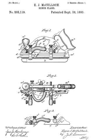
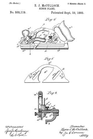
Figure 1 is a side elevation of a plane embodying this invention; Fig. 2 a plan view thereof; Fig. 3 a side elevation of the body portion of the auxiliary stock detached; Fig. 4 a side elevation similar to Fig. 1, but with the gage removed; Fig. 5 a side elevation of the blade of the auxiliary stock detached, and Fig. 6 a transverse section on the broken line x6–x, Fig. 4.
The main portion aof the stock having the handles a2 and the blade or sole piece a3, the iron or cutter clamp a4 and the lateral rods a5, as well as the gage or fence b supported on said rods a5, may be of any suitable or usual construction, being herein shown as the same as in the bench plane shown in Letters Patent No. 294,825, before mentioned. The body portion c of the auxiliary stock may also be the same as in said patent except as to the means for connecting it with the blade or sole piece d, of said auxiliary stock, the said body portion being provided with sockets c2 to engage with the lateral rods a5 upon which the said auxiliary stock is adjustable laterally toward and from the main portion of the stock as in the patent before referred to, being secured in adjusted position thereon by suitable clamping screws c3. The said auxiliary stock has a suitable recess to accommodate the iron or cutter e and the portions at the front and rear of the cutter recess are connected by a lateral arch c4 which affords a free opening for the escape of shavings. Instead of having the blade or sole piece of the auxiliary stock made in two pieces each riveted or rigidly fastened to the body portion, one at the front and the other at the rear of the cutter recess, as in the before mentioned patent, so that nothing but lateral adjustability is provided for the sole portion of the auxiliary stock with relation to that of the main stock, the said blade or sole portion d is in accordance with the present invention preferably made in a single piece as best shown in Fig. 5, having a suitable recess d2 to accommodate the iron e and permit the escape of the shavings; or in other words the portions of said blade that are at the front and rear of the cutter or iron are connected by a portion d3 that extends over the top of the iron and the space in front of it. The said blade d is adjustably connected with the auxiliary portion c of the stock so that the lower edge of the said blade, forming the sole of the auxiliary stock, may be adjusted up and down with relation to the sole portion or blade of the main stock, as may be required to bring it to the proper relation to the cutter or iron when the edge of the latter is of such shape (as for example in the one shown in Fig. 6) that the portion of its edge which is nearest to the auxiliary stock must be at a different level from the edge of the blade a3 of the main stock in order to co-operate properly with the cutter. It is necessary for the proper co-operation of the blade d and the cutter e that the up and down adjustment of the blade d should be in line with the inclined cutter, and to properly provide for this the blade d is provided with slots d4 which embrace the lateral pins a5 of the main stock, while permitting the blade d to move up and down diagonally with relation thereto, and the body portion c of the auxiliary stock is provided with similarly inclined slots c5 to engage with fastening devices shown as clamping screws f extending into suitable holes d5 in the blade d. Thus by loosening the screws f the blade d may be slid up and down in line with the cutter e until its lower edge or sole portion is brought to the proper height to co-operate properly with the adjacent portion of the cutter so as to afford an additional or auxiliary support besides that afforded by the blade a3 of the main stock to regulate the depth of the cut and to guide the plane along the material being planed. The amount of up and down adjustment may be increased beyond the length of the slot c5 in the body of the auxiliary stock by having two or more suitably threaded screw holes d5 at different levels as shown in Fig. 5. By this construction the lower edge or sole portion of the blade of the auxiliary stock may be adjusted to any desired position both laterally and vertically with relation to the lower edge of the blade of the main stock, and the two thus constitute a universally adjustable stock which may be used with irons or cutters of any width and any shape of cutting edge within the limits commonly required for cutters having other than straight edges, thus greatly increasing the capacity of the tool over that of one in which there is no vertical adjustment of one portion of the stock relative to the other, so that it is in fact adjustable in width only.
I claim-
l. The combination of the main stock having a blade fixed thereon with an auxiliary stock laterally adjustable with relation to said main stock, and a blade supported on said auxiliary stock and vertically adjustable thereon, substantially as and for the purpose described.
2. The combination of the main stock having a blade fixed thereon and lateral rods or pins, with an auxiliary stock adjustably supported on said rods, a blade connected with the said auxiliary stock having slots parallel with the iron or cutter of the plane embracing the rods, and means for fastening the said blade at different heights on said auxiliary stock, substantially as described.
3. The combination of the main stock, its blade, and rods projecting laterally from said stock; with the auxiliary stock adjustably supported on said rods and provided with slots c5 parallel with the iron or cutter of the plane, the blade d provided with a recess for the cutter, and having slots d4 parallel with the cutter embracing the rods of the main stock, and clamping screws f extending through the slots of the auxiliary stock, substantially as and for the purpose described.
In testimony whereof I have signed my name to this specification in the presence of two subscribing witnesses.
EPPIE J. McCULLOCH.
Witnesses:
CHAS. E. COCHRAN,
P. J. O’DONNELL.