No. 1,354,651 – Extension Attachment For Carpenters’ Planes (Iver James) (1920)
[paiddownloads id=”726″]1354651


UNITED STATES PATENT OFFICE.

_________________

IVER JAMES, OF SEATTLE, WASHINGTON.

EXTENSION ATTACHMENT FOR CARPENTERS’ PLANES.

_________________

SPECIFICATION of Letters Patent No. 1,354,651, dated December 18, 1855.
Application filed December 18, 1880. (No model.)

1,354,651. Specification of Letters Patent. Patented Oct. 5, 1920.
Application filed November 24, 1919. Serial No. 340,107.

_________________

To all whom it may concern:

Be it known that I, IVER JAMES, a citizen of the United States, residing at Seattle, in the county of King and State of Washington, have invented a certain new and useful Improvement in Extension Attachments for Carpenters’ Planes, of which the following is a specification.

My invention relates to improvements in attachments for carpenters’ planes of the type commonly used for planing lumber, and the object of my improvement is to provide a strong, simple, and relatively cheap attachment by which a plane of short length as an ordinary jack plane or smoothing plane can be quicldy and easily converted into a longer plane as a jointer, without any substantial alteration of the shorter plane.

A further object is to provide novel, efficient and quickly releasable means for rigidly securing the attachment to the shorter plane.

The invention consists in the novel construction of an attachment for a carpenter’s plane and in the novel construction, adaptation and combination of parts by which such attachment is secured to a plane as will be more clearly hereinafter described and claimed.

Certain classes of carpentry work require the use of a short plane, while other classes of work require the use of longer planes, thus making it necessary for the carpenter doing ordinary work to provide himself with two or more separate planes that are substantially identical, except as to the length of the base or body portion of the plane. The present invention contemplates the use of an extension in the form of a separable base or body portion, by which a shorter plane may be converted into a longer plane.

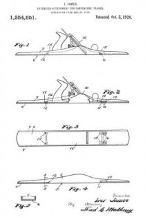
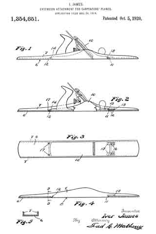
In the accompanying drawings Figure 1 is a view in side elevation of an extension constructed in accordance with my invention as it may appear when it has a plane installed therein; Fig. 2 is a view in longitudinal section of the same, parts of the plane being shown in elevation; Fig. 3 is a plan view of the bottom of the plane and extension that are shown in Figs. 1 and 2; Fig. 4 is a detached view in longitudinal section of the extension and Fig. 5 is a view in cross section on broken lines 5, 5 of Fig. 4.

Like reference numerals designate like parts throughout the several views.

The extension comprises a relatively long, channel shaped member, having a flat straight bottom wall 6 that is provided with upwardly projecting integral side flanges or side walls 7 that are preferably of greater width at the center and taper toward the ends of the extension in substantially the same manner as the sides of the body portion of an ordinary plane.

The central portion of the bottom wall 6 is cut away as at 8 to leave an opening of the same width and of slightly shorter length than the bottom of a jack plane or smoothing plane 10 on which the attachment is to be used and the bottom 6 at the front and rear ends of the opening 8 is beveled as at 11 and 12 respectively to fit the correspondingly beveled ends 13 and 14 of the plane 10.

The devices for engaging with and holding the front end of the plane 10 comprise two metal strips or dogs 15 that are permanently secured to the bottom 6 by rivets 16 and overhang the beveled portion 11 so that the front end of the plane 10 may be inserted thereunder as shown in Fig. 2.

The rear end of the plane 10 is rigidly secured to the bottom 6 of the extension member by screws 17 that screw into the bottom 6 and whose heads overlap and engage with the beveled end 14 of the plane.

The beveled ends 13 and 14 are the only alterations that are made on the plane 10 and these alterations do not interfere with the use of such plane as a jack plane or smoothing plane when the extension is removed.

When the plane 10 is secured in the attachment the bottom of the plane is exactly flush with the bottom of the attachment so that the device will function in the same manner as a jointer plane.

The sides of the attachment are spaced just far enough apart so that the plane 10 will fit snugly therebetween and the dogs or strips, 15 and screws 17 serve to fixedly secure the plane and the attachment together so that there is no relative movement therebetween.

The attachment is not heavy or cumbersome when carried in a tool chest, is not expensive to manufacture, is strong in construction, is ea.sy to attach to and detach from a plane and may be readily used for converting a shorter plane into a longer one, thereby enabling a carpenter to dispense with one of the tools that is required in ordinary work.

While the device is described as being particularly well adapted for converting a jack plane or smoothing plane into a jointer piane, it will be understood that it may be used for converting any short plane into a longer one.

Obviously changes in the form, dimensions and arrangement of parts of this device may be resorted to within the scope of the following claims.

What I claim is:

1. An extension for a carpenter’s plane comprising a relatively long, straight, fiat bottomed member of channel shaped cross section having the central portion of its bottom cut away to permit the insertion of a carpenter’s plane, the said bottom being beveled at the ends of said cut away portion to fit correspondingly beveled ends on said plane and means for securing said extension to the ends of said plane.

2. The combination with a relatively short carpenter’s plane that has its ends beveled from the bottom upwardly of a relatively long, straight, flat bottorned extension member of channel shaped cross section and having its central bottom portion cut away and having the said bottom beveled at the ends of said cut away portion to fit the beveled ends of said plane, dogs rigidly secured to said extension member and overhanging one of said beveled portions and screws. in said extension at the other of said beveled portions, the said dogs and the said screws serving to secure said extension to said plane.

Signed at Seattle, Washington, this 12th day of November 1919.

IVER JAMES.

No. 1,291,856 – Plane (Louis Haneberg) (1919)

[paiddownloads id=”722″]1291856


UNITED STATES PATENT OFFICE.

_________________

LOUIS HANEBERG, OF BULLRUN, OREGON.

PLANE.

_________________

1,291,856. Specification of Letters Patent. Patented Jan. 21, 1919.
Application filed May 4, 1918. Serial No. 232,617.

_________________

To all whom it may concern:

Be it known that I, LOUIS HANEBERG, a citizen of the United States, residing at Bullrun, in the county of Clackamas and State of Oregon, have invented new and useful Improvements in Planes, of which the following is a specification.

This invention relates to improvements in planes for use by carpenters and other workers in wood and especially with reference to the provision of a tool of this character which may be adjusted or modified in size and thereby adapted for use either as a smoothing plane, a jack-plane or a jointer-plane, as may be desired.

The invention consists in the construction, combination and arrangement of devices hereinafter described and claimed.

In the accompanying drawings:–

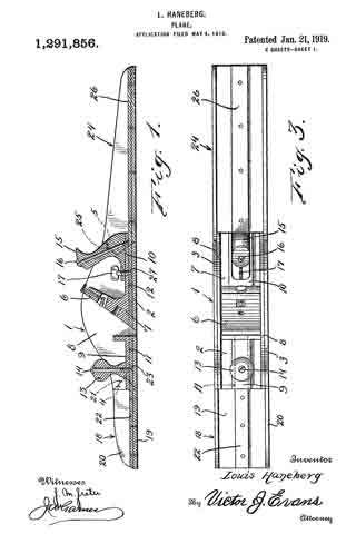
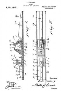
Figure 1 is a vertical longitudinal sectional view of a plane constructed in accordance with my invention, and showing the same arranged for use as a jointer-plane.

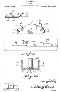
Fig. 2 is an elevation of the same, with the parts disconnected from one another.

Fig. 3 is a plan of the same.

Fig. 4 is a vertical transverse sectional view of the same.

My improved plane comprises a central member or body 1, which is made of iron or steel and comprises a shoe or bottom 2 and side walls or flanges 3. Said walls or flanges are provided in their ends with V-shaped dovetail notches 4, 5 which are reversely arranged as shown, and are respectively at the front and rear ends of the member 1. The frog 6 on which the usual bit is placed is also made of metal and is integral with a plate which bears on the bottom 2 and is formed with side flanges or walls 8 which are secured to the inner sides of the side walls 3 and are co-extensive therewith so that the said flanges or walls 8 form bottoms for the dovetail notches. The central portion of the plate 7 is formed with longitudinally arranged offsets 9, 10 which form slots 11, 12 which extend respectively to the front and rear ends of the member 1. The usual knob 13 is secured on the offset 9 by a screw 14, the lower end of which is conical in form. The usual handle 15 is secured on the oJi`set 10 by a screw 16 and also by a set-screw 17, the lower end of the set-screw being conical.

The body 1 when equipped with a suitable bit forms a smoothing plane.

An extension 18 is provided for the front end of the plane and to form a jack-plane when said extension is attached to the front end of the body 1. The said extension is made of iron or steel and comprises a bottom or shoe 19 and side walls or flanges 20, the rear ends of which are V-shaped as at 21, to form dovetail tongues which are adapted to closely fit in the dovetail notches 4. In the bottom of the extension 18 is a connecting plate 22 which is secured thereto and the rear ortion of which extends rearwardly therefrom and is adapted to enter the slot 11 and is provided with an inverted conical opening 23 for engagement by the lower end of the screw 14 so that the screw serves to firmly draw and clamp the extension 18 against the rear end of the body or member 1 as well as to secure the knob 13 in place.

When the extension 18 is thus secured to the rear end of the member 1 the plane is arranged for use as a jack-plane, as will be understood.

I also provide a rear extension 24 which is similar in construction to the construction 18 and the side walls of which are provided at their front ends with V-shaped tongues 25 to enter the notches 5. The connecting plate 26 of the extension 24 projects at its front portion from the front end of said extension and is adapted to enter the slot 12 and has a conical opening 27 with which the conical lower end of the set-screw 17 engages so that said set-screw serves to closely draw and clamp said extension 24 to the rear end of the member 1.

When the extension 24 is thus secured the plane forms a jointer-plane.

Owing to the provision of the side walls 8 of the frog member 6 and which cover the inner sides of the dovetail notches the dove-tail projections or tongues of the front and rear extensions bear directly against said walls or flanges 8 and lateral displacement of the extensions 18 and 24 is absolutely prevented so that the side walls of the main member 1 and the extensions 18 and 24 all lie in exactly the same planes and present unobstructed smooth outer surfaces, adapting the plane for use on fine work.

While I have herein shown and described a preferred form of my invention, I would have it understood that changes may be made in the form, proportion and construction of the several parts, without departing from the spirit of my invention and within the scope of the appended claims.

Having thus described my invention, I claim :–

1. In a plane, a main member having a longitudinally arranged slot, an extension member having a connecting plate projecting therefrom and arranged to enter the slot, a handle on the main member and a screw securing the handle to the main member and also securing the plate in the slot.

2. In a plane, a main member having a longitudinally arranged slot, an extension member having a connecting plate projecting therefrom and arranged to enter the slot, a handle on the main member and a screw securing the handle to the main member and also securing the plate in the slot, said plate having a conical opening and the screw having a conical point to engage in said opening.

3. In a plane, a main member having side walls provided with notches at the ends, said main member being also provided with a frog member having side walls which form the inner sides or bottoms of said notches, extension members for the plane having side walls provided with projections to enter said notches and means to detachably secure said extension members.

4. In a plane, a main member, a frog member in the main member and provided with a bottom portion having an offset forming a longitudinal slot, and an extension member having a plate projecting therefrom and arranged to engage in said slot.

In testimony whereof I affix my signature.

LOUIS HANEBERG.

_________________

Copies of this patent may be obtained for five cents each, by addressing the “Commissioner of Patents, Washington, D. C.”
_________________

No. 1,102,095 – Plane (John Smith) (1914)

[paiddownloads id=”698″]1102095


UNITED STATES PATENT OFFICE.

_________________

JOHN SMITH, OF POOLER, GEORGIA.

PLANE.

_________________

1,102,095. Specification of Letters Patent. Patented June 30, 1914.
Application filed October 9, 1913. Serial No. 794,225.

_________________

To all whom it may concern:

Be it known that I, JOHN SMITH, a citizen of the United States, and a resident of Pooler, in the county Of Chatham and State of Georgia, have invented a new and Improved Plane, of which the following is a full, clear, and exact description.

This invention relates to woodworking tools and has particular reference to the construction of carpenters’ planes whereby a tool of this character may be adjusted or modified in size and thereby made to serve as a substitute for several different sizes of planes commonly required by a carpenter.

The primary object of the invention, therefore, is to provide a tool of the class indicated which is adapted by the provision of one or more extensions to take the place of a set of planes including a smoothing or block plane, a jack plane, a fore-plane and a jointer.

The foregoing and other objects of the invention will hereinafter be more fully described and claimed and illustrated in the drawings forming a part of this specification in which like characters of reference indicate corresponding parts in all the views, and in which —

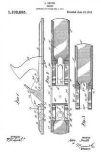
Figure 1 is a longitudinal section invention arranged as a jointer; Fig. 2 is a plan view of the same; and Fig. 3 is view of the rear extension detached.

The several parts of the device may be made of any suitable materials, and the relative sizes and proportions, as well as the general design of the mechanism, may be varied to a considerable extent without departing from the spirit of the invention hereinafter more fully set forth and specifically claimed.

A device made in accordance with this invention comprises a head or body 10 having a throat or mouth 11 for the accommodation of the usual bit and frog (not shown), and nsually provided also with a handle 12 and a knob 13, especially when made of metal. As is usual in the construction of metal planes there are provided vertical side flanges 14 extending from one end to the other of the body 10 and between which the supporting means 15 for the bit are arranged.

The body 10 to which the handle and knob are connected permanently constitutes what is commonly termed a block or smoothing plane, and in order to constitute such of the a plan implement into a jack plane an extension 16 is added to the front end thereof. Said extension 16 comprises a flat portion constituting an extension of the base of the body 10 and is provided on its lateral edges with reinforcement ribs 17 each having an arm 18 extending rearwardly in close engagement with the inner surface of the adjacent flange 14. Said arms span the joint between the main base and the extension and adjacent their rear ends I provide means to temporarily lock the extension to the front end of the body 10. As shown herein said locking means comprises a pair of studs 19 extending inwardly from the inner surfaces of the flanges 14 just above the rear ends of the arms 18. Preferably said arms are adapted to slip directly beneath and in close contact with said studs, as shown in Fig. 1. I also provide spring catches 20 which engage over the studs 19 and serve to prevent longitudinal displacement of the extension 16. The studs serve, therefore, directly to prevent the rear ends of the arms from tilting up and through the catchers 20 they prevent longitudinal movement, as above set forth. The principal strain, however, upon the extension would tend to be upward or in a direction to cause the front end of the extension to be elevated above the plane of the bottom of the implement. This tendency, however, is resisted effectively by means of a lip 21 extending into a rabbet 21′ formed across the end of the lower surface of the body 10. Said lip and rabbet are provided preferably with right angles and hence will not interfere with the aforesaid slidable movement of the extension when putting it in place. Lateral distortion or twisting of the parts is prevented by the fact that the arms have close engagement with the inner surfaces of the flanges 14 and also by the fact of the shoulders 22 cooperating with the ends of said flanges.

In order to constitute the implement into a jointer I provide a rearward extension 16′ preferably longer than the extension 16 but of the same general character, the same including a pair of arms 18′ each having a spring catch 20′ cooperating with a stud 19 in a manner similar to that above described. The ribs 17′ of this form of the invention reinforce and stiffen this member. This rearward extension 16′ also is provided with a lip or lips 21a extending forwardly on opposite sides of the base of the handle 12 into cooperation with the rabbet 21′, as shown in Fig. 1. The base of this extension is provided with a socket or notch 16a into which the base of the handle is snugly seated when the extension is shoved forwardly into place. Either of these extensions may be almost instantly attached or detached. The manner of detachment may consist in the holding of the body 10 in one hand and with the other hand spanning the handle or knob and causing two of the fingers of such hand to lift upon the free ends 20a of the catches. Such handle or knob constitutes therefore a fulcrum to assist in such lifting movement, and the pressure between the hand and the ends of the fingers causes sufficient outward or rearward movement of the extension to unlock the catches from the studs. The two parts, then, may be pulled apart directly without resistance. The assembling movement will be readily understood from what has been said above, and requires but a simple shove of the extension directly into its place, the ends 20a of the catches causing the catches to ride automatically over and into engagement with the studs.

Having thus described my invention, I claim as new and desire to secure by Letters Patent:–

1. In an implement of the class set forth the combination of a main plane body having a base and upwardly extending side flanges, an extension for said body comprising a base adapted to aline with the body base, said extension also including a pair of arms extending along the body base adjacent the inner surfaces of said flanges, a pair of studs secured to said iianges and extending toward each other in contact with the upper surfaces of said arms to prevent downward tilting of the extension, and means engaging over said studs to prevent longitudinal displacement of the extension.

2. In a plane, the combination with a main body including a base and a pair of upwardly extending lateral flanges, of an extension for either end of said base, said extension comprising a base adapted to aline with the aforesaid base and also including a pair of arms extending along the top of the main base just within the flanges thereof, a pair of studs cooperating directly with the upper surfaces of said arms, a pair of spring catches secured to the arms and adapted to snap automatically over said studs when the extension is shoved into place, and means cooperating with said arms to prevent the upward tilting of the extension.

3. In a plane, the combination of a main body including a base, vertical side flanges extending upwardly from the base, and a pair of studs extending inwardly from the inner faces of said side flanges in alinement with each other and spaced above the upper surface of said base, an extension for the main body including a base adapted to abut against the aforesaid body base, a pair of rigid arms extending from the extension and lying snugly between said studs and the main body base, and means on the arms cooperating with said arms and studs serving to prevent accidental removal of the extension from the base.

In testimony whereof I have signed my name to this specification in the presence of two subscribing witnesses.

JOHN SMITH.

Witnesses:
JOHN B. SMITH,
E. CARMEL MURPHY.

_________________

Copies of this patent may be obtained for five cents each, by addressing the “Commissioner of Patents, Washington, D. C.”
_________________

No. 946,178 – Combination Woodworking-Plane (Mardonious L. Carter) (1909)

[paiddownloads id=”667″]946178


UNITED STATES PATENT OFFICE.

_________________

MARDONIOUS L. CARTER, OF GLASSPORT, PENNSYLVANIA.

COMBINATION WOODWORKING-PLANE.

_________________

946,178. Specification of Letters Patent. Patented Dec. 14, 1909.
Application filed February 13, 1909. Serial No. 477,535.

_________________

To all whom it may concern:

Be it known that I, MARDONIOUS L. CARTER, a citizen of the United States, residing at Glassport, in the county of Allegheny and State of Pennsylvania, have invented certain new and useful Improvements in Combination Woodworking-Planes; and I do declare the following to be a full, clear, and exact description of the invention, such as will enable others skilled in the art to which it appertains to make and use the same, reference being had to the accompanying drawings, and to the letters and figures of reference marked thereon, which form a part of this specification.

This invention relates to an improved combination wood-working plane for carpenters’ use, and it comprises a plane proper carrying the bits which in itself forms what is known in the art as a “smoothing plane” a detachable rear extension and means for securing the same which when in position converts said smoothing plane into a “jack plane” or one of greater length and by a further addition of a forward extension in addition to that of the rear the plane answers the purpose of a “fore plane”, and the invention further consists in the certain details of construction of parts as will be fully described hereinafter.

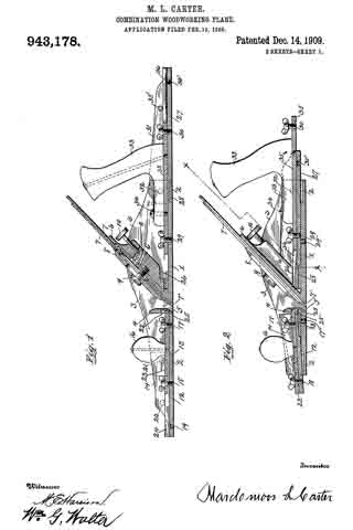
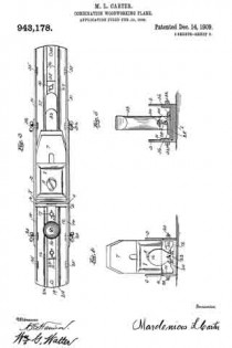
In the accompanying drawings:– Figure 1, is a central side sectional elevation of my improved combination plane showing the same converted into a fore-plane, the same being constructed and arranged in accordance with my invention. Fig. 2 is a similar view partly in elevation, showing the implement converted into at smoothing plane, the rear and forward extensions being adjusted and secured above the level of the base of same. Fig. 3 is a plan view of the converted fore plane, as shown at Fig. 1. Fig. 4; is an end elevation of the same. Fig. 5 is a cross section, taken on the line x x of Fig. 1.

To put my invention into practice and thereby construct a convertible hand plane for carpenters’ and joiners’ use and provide a combination of these planes in one, I form from cast metal a middle section which comprises a flat base 1, upwardly projecting sides 3, extending the entire length of said base, a cross portion 4 located above the throat 5 and an inclined integral rest 6 upon which the bits 7 are held by means of a plate 3 and screw 9 and rigidly secured by a thumb screw 10 operating in connection with a pivoted dog 11.

The above described construction differs but slightly from an ordinary smoothing plane such as are now in common use.

The base 1 of the middle section is rabbeted or reduced to one-half its thickness both at its forward and rear ends 2, and two threaded openings 17′–29′ formed through the base, and suitably located openings in the two side flanges 3 for the reception thumb screws 20 and 32 for the purpose securing the front and rear extensions, as will be fully described hereinafter.

The rear extension of the plane consists of a flat base 27 having side flanges 31, a rabbeted or reduced forward end 28 to register with and engage with the reduced rear end of the plane proper. Formed with this base 27 are parallel arranged dovetailed slides 36, which extend in the direction of its length and are adapted to contain a sliding dovetailed strip 35, in such manner that said strip may move freely therein. This strip 35 is secured rigidly in a certain position by means of thumb screws 29–30, engaging with the threaded opening 29′ in the base 1 of the plane proper and with a similar opening 30′ formed in the base of the extension, as will be best seen by reference to Fig. 1 of the drawings. This rearward extension is further secured and made more rigid with the plane proper by means of thumb screws 32 passing through the side flanges 3 and engaging with threaded openings formed in the flanges 31 of said extension (see Figs. 3 and 5) this making a permanent and rigid connection between the parts. The movable dovetailed member 35 carries an ordinary handle 33, such as are used on all wood planes said handle being attached by a screw 34 at the forward end and by another passing down through the same.

At the rear end of the base 27 of the rear extension is a threaded opening 30, and like openings 35′ are formed in the side flanges of the same, by means of which together with the thumb screws 32, this said extension may be adjusted to the position shown at Fig. 2 of the drawings, having first released the screws 29–30, moved the sliding member 35 back until the thumb screw 29 may engage with the forward threaded opening of the base 27 at which time the side screws 32 are adjusted to make a rigid connection of the parts. This backward movement of the sliding member 35 will bring the handle 33 and adjust the other parts to form the smoothing plane, the whole having been moved forward and on the top of the base 1 of the plane proper, and when in this position the forward extremity of the guides 36 will project beneath an offset 26 formed beneath the inclined bit rest 6′ and prevent any lateral or vertical movement of the extension.

The forward end of the plane proper is also fitted with an adjustable extension, the same consisting of a base 12, rabbeted to register with the front rabbet of the base 1, side flanges 14, parallel dovetailed guides 24 in which a corresponding movable member 23 operates in the direction of its length. This forward extension is secured in line with the plane proper by means of two thumb screws 17 and 18, together with side screws 20 in the same manner as that of the previously described rear extension. The sliding member 23 carries a knob or hand hold 16, common to planes of this class and when the said extension is in position to form a fore plane (as at Fig. 1) said sliding member is projected into a slot 25 formed at the base of the partition 41, and the extension held rigid with the plane proper by thumb screws 17 and 18, engaging the base of said extension and with the base of the plane proper. In addition to these two securing screws 17–18, side screws 20 are used which pass through the fianges of the two members, as will be seen by reference to Figs. 1 and 4.

To adjust the forward extension when the implement is to be used as a smoothing or jack plane the two screws 17–18 are released, the sliding member 23 moved back and the one screw 18 engaged with the threaded opening 19 and the extension more to a position on the top of the base 1 of the plane proper, the rear end of the sliding member 23 entering a pocket 22 formed in the partition at and the rear end of the base resting upon strips 25′ (see Fig. 2). The extension is now secured in this position by the side clamping screws 20.

By placing the front and rear extensions in position as at Fig. 1, a fore plane is formed, the handle 33 being first adjusted to the proper position.

To form a jack plane it is only necessary to adjust the forward extension to the position shown at Fig. 2, leaving the rear extension adjusted as shown at Fig. 1, and in order to convert the implement into a smoothing plane the front and rear extensions occupy a position as shown at Fig. 2.

The advantages of a convertible plane construction, as described are many, as is obvious among which are cheapness, as it takes the place of the three ordinary smoothing planes required for all ordinary carpenters’
practice, and it may be adjusted to occupy the minimum of space in a carpenter’s tool chest.

Various slight modifications and changes may be made in the details of construction without departing from the spirit of the invention. Therefore, I do not wish to confine myself to the construction, shown and described, but wish to claim all such modified forms as would come properly within the general scope of the invention.

Having thus described my invention, what I claim and desire to secure by Letters Patent, is:–

1. A bench plane, comprising a. plane proper, an extension therefor, means for attaching the extension with its sole in line with the plane sole, or with the sole in contact with the inner sides of the main sole plate, and a handle adjustable along the extension.

2. A bench plane, comprising a plane proper, a rearward extension therefor, means for attaching the extension with its sole in line with the plane sole, or with its sole in contact with the inner side of the main sole plate, and a handle adjustable along the extension, in combination with a forward extension, an adjustable knob carried by said extension, and means for locking said adjustable knob and extension to the plane proper.

In testiniony whereof, I affix my signature, in presence of two witnesses.

MARDONIOUS L. CARTER.

Witnesses:
W. G. WALTER,
ARTHUR V. McKEE.

No. 869,016 – Extension-Plane (John V. Petrusich) (1907)

[paiddownloads id=”649″]869016


UNITED STATES PATENT OFFICE.

_________________

JOHN V. PETRUSICH, OF CHICAGO, ILLINOIS.

EXTENSION-PLANE.

_________________

869,016. Specification of Letters Patent. Patented Oct. 22, 1907.
Application filed June 17, 1907. Serial No. 379,311.

_________________

To all whom it may concern:

Be it known that I, JOHN V. PETRUSICH, a citizen of the United States, residing at Chicago, in the county of Cook and State of Illinois, have invented a new and useful Extension-Plane, of which the following is a specification.

This invention relates to improvements in planes.

It is well known that carpenters and others using this class of tool find occasion to use several sizes of the same and the object of this invention is to provide what may be termed an extension plane or a plane in which the several essential sizes of the tool are combined in one.

With this and other objects in view the invention consists in the construction and combination of parts to be hereinafter described, pointed out and claimed in the following specification and illustrated in the accompanying drawings, in which:–

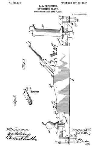
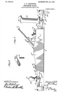
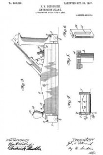
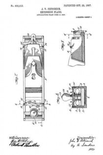
Figure 1 is a side elevation of the device complete. Fig. 2 is a detail of a slotted bar and pin therefor used for locking the extension members. Fig. 3 is a view similar to Fig. 1 showing in dotted lines the position of the extension members when the plane is closed. Fig. 4 is an end of the device partly in section and taken on line d–d Fig. 9. Fig. 5 is a view in section of Fig. 4 taken on line a–a. Fig. 6 is a detail perspective of the rack employed in the extension portion of the device. Fig. 7 is a plan view of the plane closed. Fig. 8 is a front view of Fig. 7, partly in section, and taken on the line b–b. Fig. 9 is a section taken on line c–c of Fig. 7.

Like reference characters indicate corresponding parts throughout the several views.

The reference numeral 2 represents a plane of ordinary or preferred construction having longitudinal sockets 2a opening in either extremity of the side walls 2b of the plane and running horizontally and parallel with each other as shown in Fig. 3.

The numeral 3 represents extension rods adapted to fit slidably into the sockets 2a and having graduations 4 on their lateral surfaces for measuring off the work. Roller-carriers 7 are provided at the external extremities of the extension rods as shown in section in Fig. 4 and as shown complete in Fig. 1, in which are pivoted the rollers 8 for the purpose of carrying the plane smoothly over the work. A brace 6 connects either pair of roller-carriers as shown in Fig. 7 for the purpose of holding the extension rods rigidly parallel.

Either roller-carrier arranged on either left-hand extension rod is recessed on the surface adjacent the roller so that it may carry a rack 10 provided with a slot 11 which engages the pivot of the roller 8. Each left-hand roller-carrier is fiuther provided with a worm 9 which engages the rack 10 for the purpose of raising and lowering the same as shown in detail in Figs. 4 and 5. When the rack 10 is dropped below the lelt-hand edge of the work it serves as a lateral drop guide to keep the plane flush with that edge of the work as shown in Fig. 1.

12 represents a knob of the plane provided with a screw 13 running the entire length of the same and protruding beyond the lower extremity thereof.

14 represents the upper section of a clamp slidably arranged on the extension rods and provided with a threaded aperture to receive the screw 13 protruding from the knob 12 which is seated on said portion of the clamp.

14a is the lower section of the clamp arranged on the extension rods in a manner similar to the upper portion and provided with a threaded aperture to receive the screw 13 that extends through the upper portion of the clamp. By turning the knob 12 to the right the sections of the clamp 14 and 14a are drawn together and are caused to grip the extension rods firmly thus affording rigid handles to the plane.

15–15 represents a pair of slotted bars arranged on the side walls of the plane by means of the screws 16 movable with said bars. The screws 16 extend vertically through the side walls of the plane to the sockets 2a and when the slotted bars are turned at right angles with the side walls of the plane the screws 16 engage the extension rods resting within the said sockets and hold them firmly.

17 represents a horizontal connecting link pivoted at 18 and engaging the slotted bars 15 in the manner shown in Fig. 7. By turning this horizontal link until it lies in a straight angle with the two slotted bars it will cause the screws 16 to engage the extension rods as above described. Thus it will be seen, the extension rods can be partly withdrawn from their sockets and locked in that position.

Either end of the plane is provided with similar extension apparatus and hence a description of that on one end is a description of the apparatus on the other.

Having fully described my invention, what I wish to claim and secure by Letters Patent of the United States is:

1. In a plane, extension means journaled in the side walls thereof, a sliding clamp mounted on said extension means, a knob seated on said sliding clamp and supporting means terminally carried by said extension means substantially as described.

2. In a plane, extension means journaled in the side walls thereof, an extension stop carried on the side walls thereof, a sliding clamp mounted on said extension means, a knob seated on said sliding clamp, roller-carriers terminally arranged on said extension means, a roller pivoted within said roller-carriers and a lateral drop guide carried by said roller-carrier substantially as described.

3. In Combination with a plane having longitudinal sockets in the side walls thereof, sliding extension rods arranged therein, a. sliding screw-actuated clamp arranged on said extension rods, a knob seated on said clamp by which the same may be anchored or released, roller-carriers terminally carried by said extension rods, a roller pivotally carried by said roller carriers, a brace 6 connecting said roller-carriers and a worm and rack carried by said roller-carriers substantially as described.

In testimony that I claim the foregoing as my own, I have hereto affixed my signature in the presence of two witnesses.

JOHN V. PETRUSICH.

Witnesses:
ROSE GREENBERG,
FREDERICK RINDLER.