No. 960,256 – Plane (Christian Bodmer) (1910)
[paiddownloads id=”671″]960256


UNITED STATES PATENT OFFICE.

_________________

CHRISTIAN BODMER, OF NEW BRITAIN, CONNECTICUT, ASSIGNOR TO THE STANLEY RULE
& LEVEL COMPANY, OF NEW BRITAIN, CONNECTICUT, A CORPORATION OF CONNECTICUT.

PLANE.

_________________

960,256. Specification of Letters Patent. Patented June 7, 1910.
Application filed January 31, 1910. Serial No. 540,967.

_________________

To all whom it may concern:

Be it known that I, CHRISTIAN BODMER, a citizen of the United States, residing at New Britain, county of Hartford, State of Connecticut, have invented certain new and useful Improvements in Planes, of which the following is a full, clear, and exact description.

My invention relates to planes and particularly to that type of plane known as a fillister or rabbet plane.

The invention has particular reference to the construction of the plane body, my object being to overcome certain weaknesses that have heretofore existed in planes of this type.

In a fillister or rabbet plane, the cutting edge of the plane-iron is made the full width of the sole, or so that the side edges of the plane iron will be coincident with the sides of the plane, whereby the cut may be formed square up to each side edge or surface of the plane body. It follows that the throat or opening in the plane sole must therefore be the full width of the sole. This results in separating the sole transversely at a point intermediate its length, and places, therefore, the entire responsibility of holding the forward and rear sections of the sole in proper spaced relation upon the single side plate of the frame. It is at this point that heretofore has not only great weakness existed, but in the casting of the plane body great difliculty has been encountered in preventing warping and twisting of the parts, tending to throw the sections out of correct alinement and making the process of machining not only laborious but exceedingly difficult. By my improvement great strength is added at this point, warping and twisting during the process of casting are prevented, and machining is simplified and expedited. The plane body is made from cast iron and since this tool is usually a hand tool, it is obvious that it must be so constructed as to withstand severe usage. Heretofore planes of this type made from cast iron as in the present case have almost always been broken across the relatively narrow connection between the two sections of the plane. By my construction such a greater degree of strength is added that there is very little danger of breakage at any point even when the tool is roughly handled. The tool being a hand tool, it is obvious that great consideration must be attached to the element of weight, since unnecessary weight unduly taxes the strength of the workman. In this connection I have constructed a plane body so that the metal is economically disposed and well balanced throughout, my aim being to secure the highest degree of stability with a mininium amount of material.

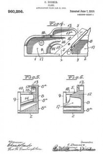
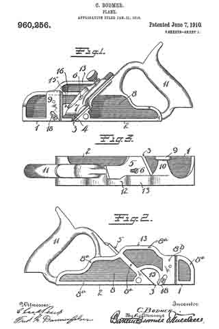
In the accompanying drawings, Figure 1 is a side elevation of the complete plane, looking up from the left hand side. Fig. 2 is a view of the reverse or right hand side of the plane body. Fig. 3 is a plan view of Fig. 2. Fig. 4 is a relatively enlarged view showing a part of the plane in longitudinal section. Fig. 5 is a cross section of the plane on the line x–x. Fig, 6 is a cross section of the plane on the line y–y.

The plane body is cast in iron or steel and comprises the forward sole section 1 and the rear sole section 2, separated by a throat 3, in which the cutting edge of the plane-iron 4 stands when the plane is set up and adjusted ready for use.

5 is a seat for the plane-iron.

The throat 3 extends transversely and obliquely entirely across the plane body as best seen in Fig. 1, and it follows therefore, that the seat 5 not only inclines rearwardly but slants down toward one side of the plane. Any suitable mechanism may be employed for holding the plane-iron to the seat, such as the headed screw-stud 6 and the cap 7. The two sections 1–2. of the sole are integrally connected by a side plate 8 formed in this instance at the right hand side of the body, a part of the side plate bridging the throat 3 and being constructed, as hereinafter described, to afford great strength and to prevent warping and twisting. The plate 8 is provided with a raised bearing portion which is machined smooth, as indicated by the laterally offset ribs 8a–8a. These bearings 8a are raised with reference to the plain unfinished side of the said side plate 8, the area of said bearing portion being suflicient to afford a sufficiently long and broad seat, at the same time being much less than the entire area, thus simplifying exceedingly the operation of machining.

9 is an upwardly projecting bearing support at the opposite side (the left hand side) of the plane body, the same being in this instance parallel with the bearing portion of the side plate 8, and at right angles to the plane of the sole sections 1–2. This bearing-section 9 is connected integrally not only with the sole section 1, but also with the opposite side plate 8, said last connections being effected through the medium of the bridge rib 10.

11 is a handle preferably cast integrally with the plane body, but of course may be made capable of being connected to said plane body in any well known or desirable manner.

Referring particularly to the views 4–6, the connections between the throat and the rib sections of the plane will now be described. It is to be understood that the plane-iron, in this type of plane, is widest at its lower end, its middle and upper portion being narrowed down to clear the side plate 8. In the present instance, I avail myself of this feature to specially construct the bridge connection between the two sole sections, providing, where necessary, a solid strong mass of material and wherever possible a ribbed construction to secure the necessary strength and lightness. Immediately adjacent to the plane seat 5, where the side plate 8 leaves the rear section, I provide a relatively heavy mass of stock, as indicated at 12, Fig. 6. Immediately forward of this point, the bridge is arched up as indicated at 13, said arch descending at a point slightly forward of the plane of the throat and meeting the transverse bridge 10 which extends across to the opposite side-bearing or support 9. The lower part of the solid mass of material 12 near the lower end of the seat 5 is extended forwardly to form a curved rib 14, which performs the double function of a strengthening rib for the plane body and a deflector for the shavings, there being a clearance space 15 entirely through the plane body above the throat 3. This rib 14 curves forwardly and across the plane and meets the sole section 1 and the inner side of the support 9, being integrally formed with both of said parts. The arched portion 13 is provided with a recess or cavity 13a and between this recess or cavity 13a and the base of the rib 14 is a horizontally disposed strengthening rib 16, extending back to the heavy mass of material 12, and serving, together with the upper flange of the bridge 13 and the rib 14, to provide a connection between the sections 1–2 of maximum strength and minimum of weight. The inside of the plane body is of course hollowed out as at 17–17 to lighten the structure.

18–18 are scoring spurs or cutters employed on opposite sides of the plane to form score lines in advance of the plane-iron 4, said score lines being coincident with the opposite edges of said plane-iron.

The part 9 performs, in addition to the function of bearing for the adjacent side of the plane, the function of a support for a depth gage, such as is customarily employed in planes of this character. The opposite side (right hand side) plate is provided with a supporting portion 8b, upon which a depth gage may be adjustably supported. Since gages and other plane attachments are well known, no particular description is required herewith, it being merely proper to state that the part 8b performs not only the function of a bearing, but also a support for any attachment such as is customarily employed in tools of this character.

As has already been stated, my invention aims at producing a plane body of the type referred to which shall be accurately formed. One of the great difficulties to overcome I will now describe. It is a well known fact that the machining of the outer flat face of a casting releases the surface tension and permits the tension on the opposite (unmachined) face to act in such a manner as to twist and warp the structure; to illustrate, were it not for the recessed form of the outer face of the side plate 8, the machining of that side to produce a bearing surface would release the surface tension on the outer side and result in warping and buckling, tending to distort and throw out of line the two sole sections 1–2 of the plane body. This buckling would occur during or immediately following the machining process. To avoid this disastrous effect, I provide a construction which requires the machining of such a relatively small area of the surface 8 that the surface tension is not released to any dangerous extent. Consequently, the tension being substantially balanced on the opposite surface of the side plate 8, all tendency to injurious warping or twisting is eliminated. It should be stated that the unmachined held of surface metal between the bearing faces 8a of the side plate 8 affords more than a mere panel intended only for the reception of a name or number. In the present instance, this unmachined surface of substantial area is so located as to overcome the aforesaid injurious tendency of warping by reason of the lessening of the surface tension at the vulnerable point.

A further advantage growing out of this construction is the rapidity and ease with which this machining process may be effected. The sum of these advantages results in great economies that add to the durability or accuracy of the instrument.

While of course I have shown herein the preferred embodiment of my invention, it is obvious that in some respects the construction may be modified or varied without changing materially those features of improvement which characterize my invention. Hence it may be stated that I contemplate that reasonable latitude may be had in the particular design resorted to.

What I claim is:

1. A plane body formed of cast metal including two sole sections separated by a throat, a wall or plate integrally connecting said sections by an arch at one side of the plane body and including a plurality of substantially horizontally disposed and inwardly directed spaced ribs extending laterally across the plane body, a standard at the opposite side of the plane forming a bearing support projecting upwardly from the forward sole section and connected to the last mentioned rib, and still another rib extending across the plane body from the support on one side to the plate on the other side and forming a combined deflector and strengthening rib.

2. A plane body formed of cast metal including two sole sections separated by a throat, a wall or plate integrally connecting said sections by an arch at one side of the plane body and including a plurality of substantially horizontally disposed and inwardly directed spaced ribs extending laterally across said body, a standard at the opposite side of the plane forming a bearing support projecting upwardly from the forward sole section and connected to the last mentioned rib, and still another rib extending across said body from the support on one side to the plate on the other side and forming a combined deflector and strengthening rib, said last mentioned rib being also integrally connected with said bearing support and one of said sole sections.

3. A plane body formed of cast metal including two sole sections separated by a throat, a wall or plate at one side, connecting said sections by an arch at one side of the plane body, a standard at the opposite side of the plane forming a bearing support, the inner side of said standard being integrally connected to the inner side of said wall or plate, the outer or bearing side of said plate where said arch is formed having a relatively raised bearing surface, said bearing surface being machined, the relatively unraised portion being unmachined to balance surface tension on opposite sides of said plate at said arch.

4. A plane body formed of cast metal including two sole sections separated by a throat, a wall or plate connecting said sections at one side of the plane body and including a plurality of substantially horizontally disposed ribs at the inner side of said side plate, the outer or bearing side of said side plate having a relatively raised bearing surface, said bearing surface being machined, said unraised portion being unmachined, said unmachined surfaces being so disposed relatively to the forward and rear sections of the sole portions of the plane as to retain surface tension at the point where buckling would tend to occur between the two sole sections.

5. A plane body comprising a forward sole section and a rear sole section arranged in line and separated by a narrow throat, a wall or plate connecting said two sections at one side of the plane body, all of said parts being formed integrally by casting, the outer bearing surface of said wall or plate including a smoothed machined bearing surface and an umnachined surface arranged in a plane slightly below the plane of the bearing surface, said unmachined portion being so located with relation to the forward and rear sole sections as to retain surface tension at the point between the front and rear sole sections where buckling would tend to occur.

CHRISTIAN BODMER.

Witnesses:
THOMAS K. O’CONNOR,
JOSEPH M. HANCE.

No. 348,198 – Variable Bench-Plane (Amos Fales) (1886)

[paiddownloads id=”413″]348198


UNITED STATES PATENT OFFICE.

_________________

AMOS FALES, OF ROCKFALL, CONNECTICUT.

VARIABLE BENCH-PLANE.

_________________

SPECIFICATION forming part of Letters Patent No. 348,198, dated August 31, 1886.
Application filed July 29, 1885. Serial No. 172,960. (Model.)

_________________

To all whom it may concern:

Be it known that I, AMOS FALES, residing in Rockfall, in the county of Middlesex and State of Connecticut, have invented Improvements in Variable Bench-Planes; and I do hereby declare that the following is a full and exact description thereof, reference being had to the accompanying drawings, making part of this specification.

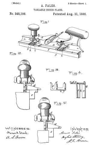
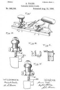
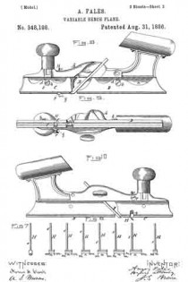
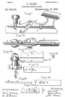
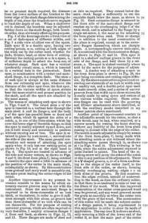
Figure 1 is a view in perspective of the main stock of the instrument as provided with my improved means of applying the fillister and grooving attachments with reversible and adjustable fence; Fig. 2, a front end view of the same; Fig. 3, a side view of one of the attaching-brackets; Fig. 4, a top view of the same; Fig. 5, a front end view of the instrument having its fence reversed for making a front fillister; Fig. 6, a front view of a set of dado-spurs of different sizes; Fig. 7, a side view of one of the spurs; Fig. 8, a side view of the main stock, with a pair of form-plates attached thereto, showing the manner in which the dado-spurs are applied; Fig. 9, a bottom view of the same; Fig. 10, a front view of a spur having only one cutting-point; Fig. 11, a side view of the main stock provided with thin removable extension-flanges for cutting extremely-narrow grooves; Fig. 12, a bottom view of the same; Fig. 13, a front end view of the same; Fig. 14, a side view of the front form-plate constructed to be adjustable lengthwise; Fig. 15, aside view of a special form of cutter used; Fig. 16, an end view of the same; Fig. 17, a top view of a cutter provided with a cap-iron attached thereto; Fig. 18, a side edge view of the same; Fig. 19, a bottom view of the same; Fig. 20, a front view of forward form-plate having a dado-spur.

Like letters designate corresponding parts in all of the figures.

The general construction of the bench-plane on which the present improvements are based is shown and described in the previous patents granted to me March 7, 1882, and April 1, 1884, and numbered, respectively, 254,542 and 295,916. Especially I will refer to one or the other of those patents for the construction of the main stock A, with its flange a, for attaching other parts of the instrument thereto, and means for securing the cutters B therein, the front and back form-plates, C D, and the reversible fence E.

Referring to those former patents, it will be noted that the front and back form-plates are attached to the downwardly-projecting stock-flange a, each by means of a single set-screw, b, fitting in a vertical notch or slot, c, of the form-plate flange d.

The first improvement herein to be described consists in the means whereby grooving and filiister attachments are applied, as shown in Figs. 1, 2, 3, 4, and 5. Two brackets, G G, are employed, constructed substantially as shown — that is, each with a vertical flange, e, having a vertical notch or slot, f, whereby it is attached to the flange a of the stock by one of the set-screws b b, used for attaching the form-plates, which are dispensed with for the special purposes of this device, and each having a horizontal flange, g, with a notch or slot, h, at right angles to the stock-flange, for attaching the reversible fence E by screws i i. The upper edges or terminations, e e e, of each bracket are in one horizontal line, in order to fit against the overhanging ledge k of the stock and serve as a guide or gage for placing the bracket in a correct position without care. Thus this entire appendage is attached to the main stock by the same means as the form-plates used for other kinds of work. Fig. 2 shows how the fence thus attached by these brackets is used for grooving.

Fig. 5 shows the fence reversed and provided with an overhanging ledge, l, for forming a front fillister. Here the ledge, being in line with the lower edge of the stock-flange a, serves for form-plates, which, for this purpose, therefore, are dispensed with. The ledge l is cut away in the middle, so not as to be in the way of the cutter, and not to interfere with the discharge of the shavings. The fence being adjustable laterally allows the grooves to be cut at any desired distance from the front edge of the material, and by employing two stocks — one arranged for grooving and the other for tonguing — no changing from one to the other kind of work is necessary for tonguing and grooving. The vertical flange of each bracket is of such height that when placed in contact with the overhanging ledge k of the main stock the grooves will be cut to the regular or greatest depth required, the distance from the lower surface of the bracket to the lower edge of the stock-flange determining the depth of cut, since the brackets serve as gages to limit the depth of cut. When a shallower cut is desired, the brackets may be adjusted farther down on the stock-flange, both brackets alike, thus obviously effecting the purpose.

Fig. 6 of the drawings shows a front view of a set of dado-spurs of different widths, and Fig. 7 a side view of either one of the spurs. Each spur H is a double spur, having two cutting-points, m m, cutting at both edges of the work cut by the cutter used, whether for dado, fillister, bead, or other form of cutting. Between the cutting-points m m is a space, n, of sufficient depth to admit the form cut, of whatever shape. Each spur has a vertical (preferably round) stem, o, which is inserted in a vertical hole in the plane-stock. Each spur, in combination with a cutter and main-stock flange, is a complete dado. The stem o of each spur is always at the same distance from one extremity and spur, whatever the distance of the other spur from the first spur, so that the various widths of spurs always bear the same relative and proper position on the stock, and all the spurs are attached by the same means.

The means of attaching each spur is shown in Figs. 8 and 9. The round stem o of the spur is inserted in a vertical hole through the main stock; A and its flange a, and the body p of the spur has parallel faces or front and back sides, which fit against the sides of a notch, q, in one of the form-plates, which lap over the lower edge of the stock-flange, so that the spur is readily adjusted up and down, and yet is held iirmly and accurately in position without turning out of line. The spur is retained in place by a set-screw, r, screwed into the side of the stock. The same general construction and means of attaching the spur apply when it only has one cutting-point, as shown in Fig. 10, and at the right hand in Fig. 6. The spurs are located in advance of the side and center cutters, as shown in Figs. 8 and 9, the front form-plate, C, being notched to receive the spur used a little in advance of the position of the cutter in the main stock, substantially as shown. By this construction cross-grained and curly wood is smoothly cut, the spur-point leading the cutter-edges of the cutter.

Another improvement in my present invention consists in the means by which extremely narrow grooves may be cut with the instrument. Since the main-stock flange is required to be three-sixteenths of an inch thick, or thereabout, in order to give it suflicient strength with this alone, no groove less than three-sixteenths of an inch wide can be cut therewith. For the purpose of cutting narrower grooves, which are often required or very desirable, I employ extension-flanges I J, front and back, as shown in Figs. 11, 12, and 13. These flanges are made of steel and as thin as required. They extend below the main-stock flange a sufficiently to cut the requisite depth below the same, as shown in Fig. 13. Each extension-flange is secured to the front side of the main-stock flange and reaches up to the overhanging ledge k of the main stock, and is attached to the flange by a single set-screw, b, the same as for attaching the form-plates when used. Thus no change in or addition to the usual construction of the plane is required, except as to the extension-flanges themselves, which are cheaply made. A correspondiugly-narrow dado-spur, H, is combined with the front extension-flange, as shown in Figs. 11 and 12. This spur is held in a shallow vertical groove in the front side of the flange, and held there by a set-screw, s. The spur is slotted vertically where held by the screw for the purpose of adjustment. A similar way of attaching a spur to the front form-plate is shown in Fig. 20, the spur being reversible and cutting-edges different. By the above construction a groove not exceeding one-sixteenth of an inch in width may be readily cut, and a double-point spur used to make smooth sides, and a series of narrow grooves from that width up to three-sixteenths is easily made by using spurs and cutters of the various widths required. These extension-flanges can be used with the grooving and fillister attachments above described, or with the auxiliary stocks described in my former patents above mentioned.

Another point of improvement consists in the adjustable mouth for the cutter, so that a wide mouth may be had, when required, or a narrow mouth for cutting the finest shaving without any liability of the front form-plate coming in contact with the edge of the cutter. The mouth is made adjustable simply by means of the front form-plate, C, being made with its attaching notch or slot widened where the attaching-screw passes through it, as shown at t in Figs. 8 and 14. This widening is but little, since the entire adjustment required is quite limited in extent. The head of the attaching-screw will cover the sides of the notch or slot in any position of its adjustment. There is a V-shaped groove, u, or of a form conforming to the shape of the cutter itself, in the front side of the cutter, as shown, forming thereby overhanging cutting-edges v v on both sides of the groove. By this construction the edges overcut, instead of undercutting in the wood, as does the ordinary cutter, so that there is no tendency to raise or tear up the fibers of the wood. With this improved construction of the cutter cross-grained wood may be grooved, and any wood grooved across the grain as smoothly as when the cutter cuts with the grain of the wood. The construction of this cutter will be made the subject-matter of a design patent, it being represented in this application in order to show its mode of application. The cap-iron K is shown as short, only covering a little of the lower end of the cutter B, so that the main part of the cutter is not incumbered therewith, and its body fits in the stock with the cap-iron, the same as if the cap-iron were not there, one form of stock, therefore, serving for such cutters as well as for all other forms of cutters used. The cap-iron is attached by a set-screw, w, passing through a slot, x, in the cutter, as shown in Fig. 19. Thereby the cap-iron is made adjustable to the edge of the cutter. This cap-iron may be applied to dado, flllister, hollow, and round cutters.

I disclaim in this invention form plates or extensions attached to the main flange, such as set forth in Letters Patent No. 295,916, granted to me April 1, 1884, wherein such extensions project at right angles to the main-stock flange, and do not and cannot extend below the said stock-flange.

I claim as my invention —

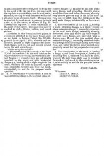
1. The combination of the stock A, the fence E, and the brackets G G, the said brackets being provided with vertical and vertically-slotted flanges e e, whereby they are adjustably attached to the stock, and with horizontal flanges g g, having slots at right angles to the stock, whereby the fence is attached in position adjustable toward and from the stock, substantially as and for the purpose herein specified.

2. In combination with the stock A and its main attaching-flange a, the vertical plane extension-flanges I J, attached to the side of the main flange, and extending directly downward therefrom and below the same, whereby very narrow grooves may be cut in the material, less in width than the thickness of the said main flange, substantially as herein set forth.

3. The combination of the stock A, having a main attaching-flange, a, a front vertical plane extension-flange, I, removably attached to the said main flange, extending directly downward from and below the lower edge of the said main flange, and provided with a double spur, H, and the rear vertical plane extension-flange, J, removably attached to the main flange and extending directly downward from and below the lower edge thereof, substantially as and for the purpose herein specified.

4. The combination of the stock A, having a flange, a, and front form-plate, G, having an attaching-slot, c, widened from front to back, whereby the said form-plate may be adjusted forward or backward by the attaching-screw b, substantially as and for the purpose herein specified.

AMOS FALES.

Witnesses:
LYMAN A. MILLS,
ERNEST F. COLES.

No. 294,825 – Bench-Plane (Justus A. Traut) (1884)

[paiddownloads id=”358″]294825


UNITED STATES PATENT OFFICE.

_________________

JUSTUS A. TRAUT, OF NEW BRITAIN, CONNECTICUT.

BENCH-PLANE.

_________________

SPECIFICATION forming part of Letters Patent No. 294,825, dated March 11, 1884.
Application filed October 17, 1883. (No model.)

_________________

To all whom it may concern:

Be it known that I, JUSTUS A. TRAUT, a citizen of the United States, residing at New Britain, in the county of Hartford and State of Connecticut, have invented certain new and useful Improvements in Bench-Planes, of which the following is a specification.

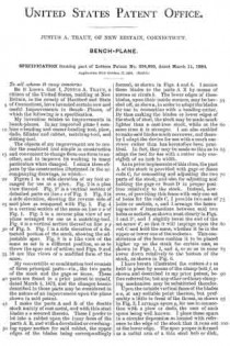
My invention relates to improvements in bench-planes. In my improved plane I combine a beading and center-beading tool, plow, dado, fillister and rabbet, matching-tool, and slitting-tool.

The objects of my improvement are to render the combined tool simple in construction and convenient to change from one form to another, and to improve its working in many particulars when changed. I attain these objects by the construction illustrated in the accompanying drawings, in which —

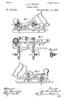
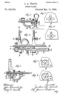
Figure 1 is a side elevation of my tool arranged for use as a plow. Fig. 2 is a plan view thereof. Fig. 2A is a vertical section of detached parts on line z z of Fig. 2. Fig. 3 is a side elevation, showing the reverse side of said plow as compared with Fig. 1. Fig. 4 is a vertical section of the same on line x x of Fig. 1. Fig. 5 is a reverse plan view of my plane arranged for use as a matching-tool. Fig. 6 is a vertical section thereof on line y y of Fig. 5. Fig. 7 is a side elevation of a detached portion of the stock, showing the adjustable spur. Fig. 8 is a like view of the same as set in a different position, so as to throw the spur out of action; and Figs. 9 and 10 are like views of a modified form of the same.

My convertible or combination tool consists of three principal parts — viz., the two parts of the stock and the gage or fence. These parts are found in a prior patent to myself, dated March 4, 1873, and the changes herein described in those parts may be considered in the nature of an improvement upon the plane shown in said patent.

I make the parts A and B of the double stock mainly of cast metal, and with thin steel blades on at secured thereto. These I prefer to let into a rabbet upon the inner faces of the parts A B, and with a dovetailed or overhanging upper surface for said rabbet, the upper edges of the blades being correspondingly formed, as shown in Figs. 4 and 6. I secure these blades to the parts A B by means of screws or rivets b. The lower edges of these blades, upon their inside corners, may be beveled off, as shown, in order to adapt the blades for use in connection with a beading-cutter. By thus making the blades or lower edges of the stock of steel, the stock may be made much lighter than a cast-iron stock, while at the same time it is stronger. I am also enabled to make said blades rnuch narrower, and thereby I adapt the device for use with a much narrower cutter than has heretofore been practical. In fact, they may be made so thin as to adapt the tool for use with a cutter only one-
eighth of an inch in width.

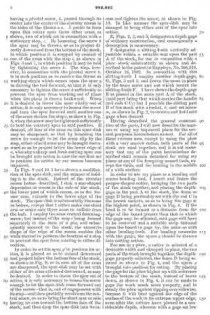
As in prior implements of this class, the part A of the stock is provided with gage or fence rods C, for connecting and adjusting the two parts of the stock, and also for adjusting and holding the gage or fence D in proper position relatively to the stock. Instead, however, of providing this fence with only one set of holes for the rods C, I provide two sets of holes or sockets, c, and I arrange the fastening-screw d’ intermediate between said two holes or sockets, as shown most clearly in Figs. 1 and 2A, and I slightly bevel the end of the set-screw d’, so that it will impinge upon the rod C and hold the same, whether it bein the upper or lower one of the sockets c. This construction of the fence enables it to be placed higher up on the stock for certain uses, as shown in Figs. 1, 3, and 4, or so as to come lower down relatively to the bottom of the stock, as shown in Fig. 6.

I have herein illustrated the cutters d e as held in place by means of the clamp-bolt f as shown and described in my prior patent, before referred to; but any other ordinary clamping mechanism may be substituted therefor.

Upon the outside vertical faces of the blades a a, at any suitable point thereon, but preferably a little in front of the throat, as shown in Fig. 3, I arrange spurs g, for use in connection with a plow or dado, the uses of such spurs being well known. I place these spurs in a circular depression so located with reference to the edge of the stock that it runs out at the lower edge. The spur proper is formed as a radial arm of a thin steel hub or disk, having a pivotal screw, h, passed through its center into the center of the circular recess in the sides of the blades a a. I prefer to form upon this rotary spur three other arms, as shown, two of which act in connection with a stationary stop, i. By loosening the screw h, the spur may be thrown so as to project directly downward from the bottom of the stock, in which position it is stopped by contact of one of the arms with the stop i, as shown in Figs. 3 and 7, in which position it may be held by tightening the screw h. The stop, however, in connection with the pivotal screw h, is in such position as to receive the thrust or working-strain which comes upon the spur g in driving the tool forward, so that it is only necessary to tighten the screw h suffiiciently to prevent the spur from working out of place when the plane is drawn backward. When it is desired to throw the spur wholly out of action, it is only necessary to loosen the screw and turn the spur forward until another one of the arms strikes the stop i, as shown in Fig. 8, when the screw may be tightened sufficiently to hold the rotatory spur in said position. If desired, all four of the arms on this spur-disk may be sharpened, so that by loosening the screw far enough to let the arms slip by the stop, either of said arms may be brought downward so as to proiect below the lower edge of a, whereby a sharp and fresh cutting-spur can he brought into action in case the one first set in position for action by any means becomes impaired.

In Figs. 9 and 10 I have shown a modification of the spur-disk, and the manner of holding it in the stock. Instead of the circular recess before described, I sink a star-shaped depression or recess in the side of the stock, the lower part of which recess, as in the former case, extends to the lower edge of the stock. The spur-disk is substantially the same as before, except that I either make one short arm or make only three arms to radiate from the hub. I employ the same central fastening-screw; but instead of the stop i being formed separately in the form of a pin, and subsequently secured to the stock, the eccentric shape of the edge of the recess enables the walls thereof to perform the function of a stop to prevent the spur from rotating in either direction.

In order to set the spur g’ in position tor action, it is placed so as to extend downward and project below the bottom face of the stock, as shown in Fig. 9; or in case all of the arms are sharpened, the spur-disk may be set with either of its arms extended downward, as may be desired. In order to throw the spur out of action, it is only necessary to loosen the screw enough to let the spur-disk come forward out of the recess — that is, out of engagement with its stop — and then partially revolve on the central screw, so as to bring the short arm or side having no arm toward the bottom face of the stock, and then drop the spur-disk into its recess and tighten the screw, as shown in Fig. 10. In like manner the spur-disk may be changed to bring either arm of the spur into action.

E, Figs. 2, 3, and 5, designates a depth-gage of ordinary construction, and consequently a description is unnecessary.

F designates a slitting-knife vertically adjustable within a suitable seat upon the part A of the stock, for use in connection with a plow-stock substantially as shown and described in the patent to Rappleye, No. 266,519, October 24, 1882. In connection with this slitting-knife I employ another depth-gage, G, Figs. 3 and 5, and fasten the same in place by the same screw and nut which secure the slitting-knife F. I have shown the depth-gage E as placed in the main part A of the stock, (said part being that which carries the handle and rods C C;) but I provide the sliding part B of the stock with a socket, k, and set-screw m, as shown in Fig. 2, to receive and hold said gage when desired.

Having described the general construction of the parts, I will now describe the manner of using my improved plane tor the several purposes hereinbefore named. For all of these various uses, except in using the plow with a very narrow cutter, both parts of the stock are used together, and it is not necessary that any of the parts hereinbefore described shall remain detached for using my plane as any of the foregoing-named tools, except the dado, and for beading in the middle of a wide surface.

In order to use my plane as a beading and center-beading tool, I insert and fasten the proper-shaped cutter, bringing the two parts of the stock together, and placing the depth-gage in the part A of the stock, the fence or gage D being preferably set with the rod C in the lowest sockets, so as to bring the gage at the highest point, as shown in Fig. 4. If the bead is to be formed at a distance from the edge of the board greater than that to which the gage may be adjusted, said gage will have to be removed and a suitable strip fastened upon the board to gage by, the same as with other beading-tools. For beading crosswise with the grain, the spurs g should be thrown into cutting action.

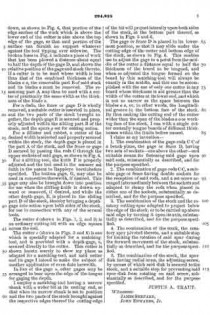
For use as a plow, a cutter is selected of a desirable width and clamped in place, the two parts of the stock brought together, the depth-gage properly adiusted, the fence D being secured as shown in Fig. 4, and the spurs g brought into position for acting. By placing the gage for the plow higher up with reference to the bottom of the stock, instead of lower down, as shown in Fig. 6, it can be made to gage the work much more properly, and to steady the plow against tipping over sidewise, because it will bear against the edge of the surface of the work to its extreme upper edge, even after the cutters have plowed to a considerable depth , whereas with a gage set low down, as shown in Fig. 6, that portion of the edge surface of the work which is above the lower end of the cutter is also above the top edge of the gage, so that said portion of the surface can furnish no support whatever against the tool tipping over sidewise. The broken lines in Fig. 4 indicate a piece of work that has been plowed a distance about equal to half the depth of the gage D, and shows the relative position of the gage and stock thereto.
If a cutter is to be used whose width is less than that of the combined thickness of the blades a a, the removable part B of said stock and its blades a must be removed. The remaining part A may then be used with a cutter of practically the same width as the thickness of the blade a.

For a dado, the fence or gage D is wholly removed, a suitable cutter is inserted in place, and the two parts of the stock brought together, the depth-gage E is secured and properly adjusted within the sliding part B of the stock, and the spurs g set for cutting action.

For a fillister and rabbet, a cutter of the desired width is selected and properly secured within the stock, the depth-gage is placed in the part A of the stock, and the fence or gage D secured by passing the rods C through the upper sockets of said gage, as shown in Fig. 6.

For a slitting-tool, the knife F is properly adjusted and the tool used in the manner set forth in the patent to Rappleye hereinbefore specified. The bottom gage, G, may also be used in connection therewith, if desired. This gage may also be brought down into position for use when the slitting-knife is drawn upward or removed, if desired, and while the other depth-gage, E, is placed in the sliding part D of the stock, thereby bringing a depth-gage into action upon both sides of the stock, for use in connection with any of the several tools.

The cutter d (shown in Figs. l, 2, and 3) is an ordinary cutting-bit with an edge square across the end.

The cutter e (shown in Figs. 5 and 6) is one which is specially adapted for a matching-tool, and is provided with a depth-gage, a, secured directly to the cutter. This cutter is shown herein merely to show my plane as adapted for a matching-tool, and said cutter and its gage I intend to make the subject of another application of even date herewith.

In lieu of the gage n, other gages may be arranged to bear upon the edge of the tongue for gaging the depth.

I employ a matching-tool having a narrow shank with a wider bit at its cutting end, so that when its narrow shank is set in position and the two parts of the stock brought against the respective edges thereof the cutting-edge of the bit will project laterally upon both sides of the stock, at the bottom part thereof, as shown in Figs. 5 and 6.

The gage or fence D is placed in its lowermost position, so that it may slide under the cutting-edge of the cutter and bottom edge of the stock, as shown in Fig. 6. This enables me to adjust the gage to a point from the middle of the cutter a distance equal to half the thickness of the board to be tongued, and when so adjusted the tongue formed on the board by this matching-tool will always be exactly in the middle, and this can be accomplished with the use of only one cutter in any board whose thickness is not greater than the width of the cutter at its lower end, and which is not so narrow as the space between the blades a a, or, in other words, the longitudinal groove in the bottom face of the stock. By thus making the cutting end of the cutter wider than the span of the blades a a or working-face of the stock, I can with a single cutter centrally tongue boards of different thicknesses within the limits before named.

I claim as my invention —

l. The combination of the gage-rods C C of a bench-plane, the gage or fence D, having two sets of sockets-one above the other-and suitable means for fastening said gage upon said rods, substantially as described, and for the purpose specified.

2. The combination of gage-rods C C, a suitable gage or fence having double sockets for the reception of said rods, and a set-screw arranged intermediately between the sockets and adapted to clamp the rods when placed in either one of the sockets, substantially as described, and for the purpose specified.

3. The combination of the stock and the rotatory cutting-spur adapted to project below the edge of the stock, or to be carried up above said edge by turning it upon its axis, substantially as described, and for the purpose specified.

4. The combination of the stock, the rotatory spur pivoted thereto, and a suitable stop for limiting the rotation of said spur during the forward movement of the stock, substantially as described, and for the purpose specified.

5. The combination of the stock, the spur-disk having radial arms, the adjusting-screw, by means of which said disk is secured to the stock, and a suitable stop for preventing said spur-disk from rotating on said screw, substantially as described, and for the purpose specified.

JUSTUS A. TRAUT.

Witnesses:
JAMES SHEPARD,
JOHN EDWARDS, Jr.

No. 148,649 – Improvement In Metallic Bench-Planes (John A. Baines) (1874)

[paiddownloads id=”227″]148649


UNITED STATES PATENT OFFICE.

_________________

JOHN A. BAINES, OF NEW YORK, N. Y.

IMPROVEMENT IN METALLIC BENCH-PLANES.

_________________

Specification forming part of Letters Patent No. 148,649, dated March 17, 1874; application filed February 9, 1874.

_________________

To all whom it may concern:

Be it known that I, JOHN A. BAINES, of New York city, in the county of New York and in the State of New York, have invented certain new and useful Improvements in Metallic Bench-Planes; and do hereby declare that the following is a full, clear, and exact description thereof, reference being had to the accompanying drawings making a part of this specification, in which —

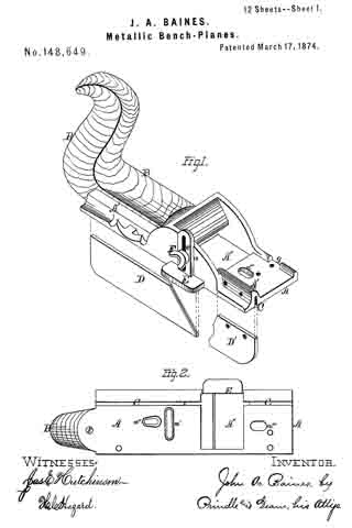
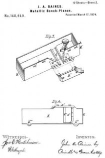
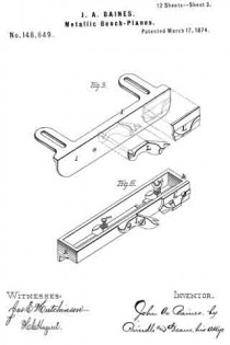
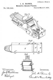
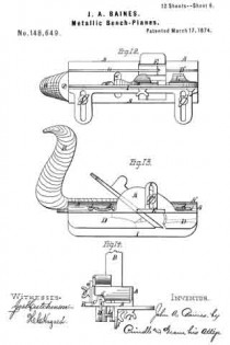
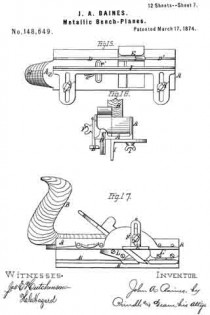
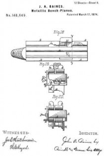
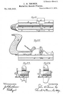
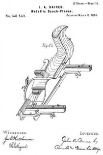
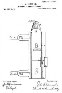
Figure 1 is a perspective view of the main frame, side gage, and sole or base plates of my plane. Fig. 2 is a plan view of the lower side of said frame. Fig. 3 is a perspective view of the detachable block or frame used for forming the smoothing and filletster planes. Fig. 4 is a plan view of the lower side of the same. Fig. 5 is a perspective view of the bottom gage. Fig. 6 is a like view of the detachable block employed for forming the sash-plane. Fig. 7 is a perspective view of the smoothing-plane complete. Fig. 8 is a plan view of the lower side of the same. Fig. 9 is a vertical section upon line x x of Fig. 8. Fig. 10 is a side elevation of the filletster-plane. Fig. 11 is a plan view of the lower side of the same. Fig. 12 is a plan view of the lower side of the tonguing-plane. Figs. 13 and 14 are, respectively, side and front elevations of the same. Fig. 15 is a plan view of the lower side of the grooving-plane. Figs. 16 and 17 are, respectively, a front and a side elevation of said plane. Fig. 18 is a plan view of the lower side of the sash-plane. Fig. 19 is a front elevation of the same. Fig. 20 is a section of said plane on line z z of Fig. 18, the cutting-tools being arranged for forming the meeting rail. Fig. 21 is a plan view of the lower side of a bead or round plane. Figs. 22 and 23 are, respectively, a side and a front elevation of the same. Fig. 24. is a front elevation of a hollow plane. Fig. 25 is a perspective view of a plow-plane. Fig. 26 is a plan view of the lower side of the same. Fig. 27 is a like view of a plane for forming center-beads. Fig. 23 is a front elevation of the same; and Fig. 29 is a side view of the cutting-irons employed, showing the shape of the cutting-edge of the same.

Letters of like name and kind refer to like parts in each of the figures.

The design of my invention is to lessen the cost and reduce the bulk of planes for producing irregular work; and to this end it consists in the construction and combination of the frame and various attachments employed for forming the different styles of plane, substantially as and for the purpose hereinafter specified.

In the annexed drawings, A represents the main frame of my tool, which has a plain lower surface, and at its upper side has such conformation as to enable it to receive the usual form of cutting-irons with the fastening-wedge, to permit the upward passage of shavings, and to provide for the attachment of a handle, B. Within the lower side, and near one edge of the frame A, is formed a narrow groove, C, which extends vertically upward within an enlargement or rib, A’, provided for the purpose, has a line parallel to the side of said frame, and receives two plates, D and D’, (shown in Fig. 1,) that form the base or sole. Two or more removable pins, d and d, pass horizontally and laterally inward through the side of said frame A, and through each of said plates D and D’, and locks the latter securely in position, when desired. Upon the inner side of the name A is formed a vertical groove, a, that receives the standard e of an adjustable gage, E, which gage is secured to or upon said frame, and held in vertical position by means of a screw, F, that passes into a threaded opening in the latter through a vertical slot in said standard.

Within the upper side of the frame A, near its ends, are formed two transverse grooves, g and g, that receive the ends of two corresponding bars, G and G’, which bars, when in position, are fastened by means of a screw, H, as shown in the front bar, or a pin, H’, as seen in the rear bar, said screw or pin being passed vertically downward through said bars into said frame. From the frame A the bars G and G’ extend laterally outward, and have their lower sides upon a line with the lower face of the former, in which position they form an extension of said face, and permit of the attachment of an angle-plate, I, (shown in Fig. 5,) which plate, being adjustable laterally toward or from the cutting-irons, forms a gage for several forms of plane. Within the lower side of the frame A, at or near its longitudinal center, is formed a transverse slot, a’; in rear of the same is provided a longitudinal slot, a”; while in front of the throat A” is a second longitudinal slot, a”’, the object of which is to enable the attachment of various parts required for forming several of the planes, said parts being described in connection with each plane of which it forms a part.

For use as a smoothing-plane, a hollow block, K, having the general form shown in Fig. 3, is placed upon the lower side of the main frame, and secured in posiuon by means of its inner side k, which extends upward into the groove C, and is provided with suitable openings k’ for the passage of the pins d and d.

The bolt k” of an adjustable throat-piece, k”’, projects upward through slots in said block and main frame and furnishes an additional means for securing said parts together.

The block K is provided with a throat, k””, which coincides with the throat of the main frame, and enables a cutting-iron, of usual form to be inserted and secured in place by means of the ordinary wedge.

To construct a filletster, the inner end of the throat k”” of the block K is uncovered by the removal of a covering plate or cap, K’, and the gage I attached to the lower face and outer side of said block, suitable threaded openings k””’ being provided within said block, for the reception of the binding-screws I’ of said gage.

The gage E is also placed in position and adjusted to depth, and, in connection with said gage I, enables the dimensions of the fillet or rabbet to be determined with certainty.

For use as a tonguing (matching) plane, the plates D and D’ are placed in position, the gage I attached to the lower face of the frame A, and upon the face of said gage is attached two blocks, L and L’, which have the form shown in Fig. 5, and perform the double office of a support for the heel of the inner half of the cutting-iron, and a gage for the depth of its cut. The gage E is also em-
ployed, its office being to insure the correct depth of cut for the outer half of said cutting-iron.

For a grooving-plane, the blocks L and L’ are removed, the gage I is moved inward to the position required by the thickness of the board, and a single cutting-tool inserted in place of the double one before used. The gage E is now reversed, so as to cause its bearing-face to extend inward nearly to the cutting-iron, the arrangement of parts being as shown in Figs. 15 and 16.

For use as a sash-plane, the plates D and D’ and the gages E and I are removed, and a block, M, having the form shown in Figs. 6 and 20, secured upon the lower side of the frame A by means of a screw, m, which extends upward through the longitudinal slot a” in said frame, and a second screw, m’, that passes downward through the transverse slot a”’ near the front end of said frame, and has its threaded end contained within a corresponding opening provided in said block. The blocks L and L’ are now attached to the inner face of the block M, where they serve as supports and gages for the cutting-iron that forms within the sash-rail the rabbet for containing glass, while the cutter for forming the molding upon said sash-rail is placed within a suitable throat formed in and through the molded face of said block M.

For use in forming the meeting rail, the gage-blocks L and L’ are removed, and the cutter shown in Fig. 20 inserted in place of that before employed for forming the glass rabbet.

For use as a beading or rounding plane, the block M is removed and a block, N, having the transverse shape shown in Fig. 23, is secured in its place upon the frame A, the size and shape of the groove it within the lower face of said blocks N and the corresponding features of the cutting-iron being varied to suit the especial purpose for which the tool is required.

To form a hollow plane, the shape of the lower face of the block N and of the edge of the cutting-iron are reversed, as shown in Fig. 24.

For use as a plow, the plates D and D’ are placed within the groove C, and the adjustable gage I secured upon the lower face of the frame A, or upon the extension–bars G and G’, after which the usual form of cutting-iron is inserted within the space between said plates, its heel resting upon the forward end of the rear plate D.

To form a center-bead plane, the extension-bars G and G’ and gage I are employed as before, the plates D and D’ are removed, and a hollow block, O, having the transverse form shown in Fig. 28, secured upon the lower face of the frame A. A cutting-iron having its lower or cutting end formed upon a line which corresponds to the grooved face of said block is placed in position within the throat o of the same, after which the plane is used in the ordinary manner.

As seen in Fig. 29, the lower end and forward side of such plane-irons as usually require caps are beveled off at an angle of about forty-five degrees with said side, so as to render more obtuse the angle of the cutting-edge, and enable any kind of wood to be cut smoothly and with ease without the use of a cap, by which means a saving is effected in the cost of said cutting-irons, and in the time and labor required in manipulating the planes.

The device thus constructed combines, in a simple and compact form, a number of tools which are usually separate, and enables them to be furnished at a comparatively small cost.

Having thus fully set forth the nature and merits of my invention, what I claim as new is —

The hereinbefore-described plane, constructed in the manner and for the purpose substantially as specified.

In testimony that I claim the foregoing, I have hereunto set my hand this 6th day of February, 1874.

JOHN A. BAINES.

Witnesses:
JOHN R. YOUNG,
JAS. E. HUTCHINSON.