
No. 277,767 – Bench-Plane (Frank A. Mershon) (1883)

UNITED STATES PATENT OFFICE.
_________________
FRANK A. MERSHON, OF PHILADELPHIA, PENNSYLVANIA.
BENCH-PLANE.
_________________
SPECIFICATION forming part of Letters Patent No. 277,767, dated May 15, 1883.
Application filed March 1, 1883. (No model.)
_________________
To all whom it may concern:
Be it known that I, FRANK A. MERSHON, a citizen ofthe United States, and a resident of Philadelphia, Pennsylvania, have invented certain Improvements in Molding-Planes, of which the following is a specification.
My invention relates to that class of molding-planes in which a wooden stock is combined with a detachable sole-plate; and the object of my invention is to afford means for readily attaching the sole-plate to and detaching it from the stock, and for steadily retaining the former on the latter, as fully described hereinafter.
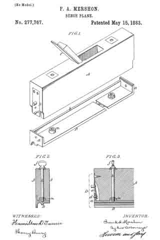
In the accompanying drawings, Figure 1 is a perspective view of my improved molding-plane, showing the sole-plate detached; Fig. 2, a transverse section, and Fig. 3 a longitudinal section of part of the plane.
The stock A of the plane is of wood and the sole-plate B of metal, the under side of this plate having such longitudinal ribs and grooves as the pattern of the molding to be planed may require. The sole-plate has at each end a transverse flange, a, and a longitudinal flange, b, fitted snugly in a recess in the stock, as shown in Fig. 2. There is at each end of the stock a spring-catch, D, for retaining the sole-plate, each catch consisting in the present instance of a spring, e, secured to the stock, and having a pin, d, for entering a hole in the transverse flange a. The stock, it should be understood, is cut away at each end to receive the said flange, and is further cut away to permit the free play of the spring, the flange being so rounded at the upper edge on the inner side that when the stock is applied to the sole-plate by depressing the former onto the latter the springs will yield without being manipulated, and will recoil when the stock reaches the plate, the pins entering the holes in the flanges, and thus holding the two parts of the plane together.
While the spring-retainers will suffice to hold the plate in place, I prefer, as an additional security, to use two set-screws, E, each provided with a head, f, constructed for the convenient turning of the screw by the finger and thumb, the stem of the screw passing through the stock, and its threaded end being adapted to a threaded projection, m, on the sole-plate. This projection is made tapering, and is adapted to an orifice of corresponding form in the under side of the stock. Even if no set-screws are used, I prefer to make these projections on the plate, as they facilitate the adjustment of the stock to its proper position on the plate, and serve as steady-pins for determining the proper lateral and longitudinal relation of the plate to the stock.
It will be seen that whenever a change in the pattern of the molding is required the plate can be readily detached to make way for another, the under side of which conforms with the desired molding, a change of plane irons or bits F being also required. The pins d are preferably tapered, so that they tend to draw the sole-plate firmly to its seat on the stock.
I claim as my invention —
1. A molding-plane in which a stock, A, provided at the ends with spring-catches, is combined with a sole-plate, B, having flanges a, constructed to be retained by the said catches of the stock, substantially as set forth.
2. The combination of the stock A, and a detachable sole-plate having tapering projections adapted to it closely correspondingly-tapered orifices in the stock, and devices, substantially as described, for securing the plate to the stock, substantially as set forth.
3. The combination of the stock A and its spring-catches with the flanged sole-plate and its tapering projections m, adapted to orifices in the stock, substantially as specified.
4. The combination ot the stock A, its spring-catches, the flanged sole-plate, and its tapering projections m, with the set-screws E.
In testimony whereof I have signed my name to this specification in the presence of two subscribing witnesses.
FRANK A. MERSHON.
Witnesses:
HARRY L. ASHENFELTER,
HARRY SMITH.