No. 466,494 – Beveling Attachment For Planes (Frank E. Hart) (1892)

UNITED STATES PATENT OFFICE.
_________________
FRANK E. HART, OF BROOKLYN, NEW YORK.
BEVELING ATTACHMENT FOR PLANES.
_________________
SPECIFICATION forming part of Letters Patent No. 466,494, dated January 5, 1892.
Application filed January 3, 1891. Serial No. 376,605. (No model.)
_________________
To all whom it may concern:
Be it known that I, FRANK E. HART, a citizen of the United States, residing in the city of Brooklyn, county of Kings, State of New York, have invented certain new and useful Improvements in Beveling Attachments for Planes, of which the following is such a full, clear, concise, and exact description as will enable others skilled in the art to which my invention appertains to make and use the same, reference being had to the accompanying drawings, forming part of this specification.
The object of my invention is to provide an attachment for a plane whereby the edge of a board, window-sash, door, or similar article may be reduced to the required angle and an accurate and predetermined bevel given without the aid of a square or other separate measure; and my invention consists in the improvements hereinafter more fully described, and pointed out in the claims.
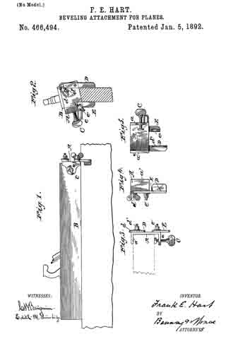
In the drawings, Figure 1 is a view in elevation of an ordinary plane fitted with the improved attachment. Fig. 2 is an end view of the same, showing the plane in action upon a beveled surface. Fig. 3 is a plan view of end of plane with attachment connected, showing top of graduated segment. Fig. 4 is a side view of attachment unconnected, and Fig. 5 is a rear view of the same.
The plate A, having flanges a a’, maybe conveniently secured to the plane B by means of the binding-screw C, and pivoted to this plate are the adjustable guiding arms or bars D and E, extending downward from opposite sides. The arms D and E of course might, if desired, be secured directly to the body of the plane The arm D is preferably formed with a slotted graduated sector d, adapted to be secured by the binding-screw d’, whereby the said arm may be held at any desired angle to the lower surface of the plane, while the arm E is shown as provided with a slotted elbow e, which, moving upon and about the screw e’, permits the arm E to be brought parallel to the arm D and also to approach and withdraw from the same. The lower ends of the guiding-arms D and E are, moreover, preferably provided with flanges d2 e2, which are shown as slightly beveled or inclined, giving thus a greater guiding-surface, while at the same time allowing the necessary oscillation and freedom in the movement of the plane. Further, the flange d2 forms a convenient rest for the finger of the artisan.
It is readily seen that when the guiding-bars D and E are adjusted to any position other than the perpendicular the plane will be made to bear unevenly, cutting more on one side than the other, until A the surface to be smoothed or reduced becomes parallel to the bottom of the plane and its slant or bevel corresponds with the inclination of the guiding-arms.
Having thus fully described my invention, what I claim as new, and desire to secure by Letters Patent, is —
l. In combination with a plane, guiding-arms pivoted thereto and extending downward from opposite sides, said arms being adapted to be secured at an angle, whereby the plane is inclined and made to bear unevenly until the surface acted on is smoothed or reduced to the slant or bevel desired, substantially as set forth.
2. In combination with a plane, a plate adapted to be secured thereto and provided with adjustable guiding-arms extending downward from opposite sides, whereby the plane is inclined and made to bear at an angle, substantially as and for the purpose set forth.
3. In combination with a plane, a plate adapted to be secured thereto, and guiding-arms pivoted to said plate and extending downward from opposite sides, the said arms being provided at their lower ends with beveled fianges, substantially as and for the purpose set forth.
4. In combination with a plane, the flanged plate B and guiding-arms D and E, having graduated sector d and slotted elbow e and flanges d2 and e2, all arranged and secured substantially as described.
FRANK E. HART.
Witnesses:
PERCY GRIFFITH,
WM. J. WINBERG.


