No. 402,886 – Bench-Plane (Frank M. Bailey) (1889)
UNITED STATES PATENT OFFICE.
_________________
FRANK M. BAILEY, OF NEW BRITAIN, CONNECTICUT, ASSIGNOR TO
THE STANLEY RULE AND LEVEL COMPANY, OF SAME PLACE.
BENCH-PLANE.
_________________
SPECIFICATION forming part of Letters Patent No. 402,886, dated May 7, 1889.
Application filed December 11, 1888. Serial No. 293,248. (No model.)
_________________
To all whom it may concern:
Be it known that I, FRANK M. BAILEY, a citizen of the United States, residing at New Britain, in the county of Hartford and State of Connecticut, have invented certain new and useful Improvements in Bench-Planes, of which the following is a specification.
My invention relates to improvements in bench-planes in which the cutting-bit is adjustable laterally; and the objects of my invention are to improve the general efliciency of the lateral adjustment, and also to effect said adjustment through the cap-screw.
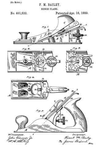
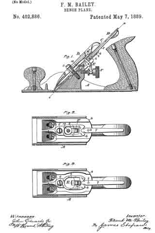
In the accompanying drawings, Figure 1 is a central longitudinal section, partly in elevation, of my plane. Fig. 2 is a transverse section thereof on the line x x of Fig. 1, and Fig. 3 is a like view showing a modification.
A designates the plane-stock, provided with the ordinary cutting-bit, B,its cap-iron C, holding-cap D, longitudinally-adjusting lever E, and its operating-nut F, all of ordinary construction.
The bed for the cutting-bit, or, as it is more generally termed, the “frog,” 4, is cut away through its middle portion to a point a little below the screw 5, by which the holding-cap is held, in order to make room for the laterally-adjusting compound lever composed of the lower member, 6, and upper member, 7, both of which are pivoted to the frog 4 on axes perpendicular to its face, the upper member by means of the pivot 8 and the lower member by means of the screw 5. The lower end of the upper member, 7, is rounded and engages a correspondingly-shaped notch at the upper end of the lower member, whereby a movement laterally of the upper member on its pivot will also move laterally the lower member, thereby enabling the lateral adjustment to be worked with ease and a very fine adjustment to be effected.
In the preferred form I provide the lower member, 6, of the compound lever, with an opening, 9, which will receive and nearly fit the head 10 of the ordinary cap-screw for holding the cap-iron C on the cutting-bit B, whereby a lateral movement of the lever, by thus engaging the cap-screw, necessitates a lateral movement of the cap-iron and cutting-bit. As the cutting-bit wears away at its lower end it will be slipped down farther on the cap-iron; but the cap-screw will always remain at nearly the same distance from the lower end of the cutting-bit, so that the laterally-adjusting mechanism always operates upon the cutting-bit at practically the same distance from its lower end.
In Fig. 3 I have shown the same construction, with the exception that I make the opening in the lower member, 6, of the compound lever large enough not to engage the cap-screw, and I provide said lower member with an upward projection, 12, which is adapted to engage the side walls of the ordinary longitudinal slot in the cutting-bit; or in the absence of said slot said upward projection may enter a hole in the cutting-bit specially adapted to receive it. This alternative form or modification may also be used in planes in which the cap-iron and cap-screw are absent.
I claim as my invention —
1. The combination of the plane-stock provided with the frog 4, the cutting-bit, andthe laterally-adjusting compound lever consisting of the lower and upper members pivoted on axes perpendicular to the face of said frog, substantially as described, and for the purpose specified.
2. The combination of the plane-stock provided with the frog 4, the compound lever consisting of the lower member, 6, having the opening 9 and upper member, 7, both pivoted to said frog, the cutting-bit B, cap-iron C, and the cap-screw 10, the head of which screw rests within the opening 9 of said lower member of the compound lever, substantially as described, and for the purpose specified.
FRANK M. BAILEY.
Witnesses:
H. S. WALTER,
H. C. HINE.