
No. 468,362 – Carpenter’s Plane (Frank Phelps) (1892)
UNITED STATES PATENT OFFICE.
_________________
FRANK PHELPS, OF AUBURN, NEW YORK.
CARPENTER’S PLANE.
_________________
SPECIFICATION forming part of Letters Patent No. 468,362, dated February 9, 1892.
Application filed April 16, 1891. Serial No. 389,185. (No model.)
_________________
To all whom it may concern:
Be it known that I, FRANK PHELPS, a citizen of the United States, residing in the city of Auburn, county of Cayuga, State of New York, have invented a new and useful Improvement in Carpenters’ Planes, of which the following is a specification, reference being had to the accompanying drawings on one sheet, making part of this specification.
My invention relates to improvements in that class of carpenters’ cutting and surface, smoothing tools generally denominated as “planes,” the stock of which is composed of wood or similar material; and the objects are to secure in such planes the advantages of trueness and freedom from wear which obtain in planes the stock of which is made of metal and at the same time retain the advantages of lightness which pertains to planes having the stock made of wood or similar material. I attain these objects by facing the ends and the sole of the stock of said plane with suitable plates of metal in the manner illustrated in the accompanying drawings, in which —
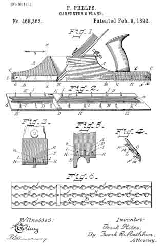
Figure 1 is a side elevation of a carpenteifs plane having a wood stock with my improvements aflixed thereto, the ends being shown in broken section, so that a clearer view may be afforded of the application of the same. Fig. 2 is a perspective view of the upper side of the metal sole-plate. Fig. 3 is a section of the stock of the plane and metal sole-plate through the line x x of Fig. 1, looking in the direction of the arrow z. Fig. 4 is a perspective view of one of the metal end plates, taken with its inner side next the point of view. Fig. 5 is an end section of a beading-plane, showing the under surface of the metal sole-plate formed for beading, but attached to the stock, as shown in Fig. 1. Fig. 6 is a plan view of the bottom side of the metal sole-plate.
Throughout the several figures similar letters refer to similar parts.
In Fig. 1 A is the wood stock of the plane. B is the metal sole-plate, and C C are the metal end plates, which are affixed thereto.
Referring to Fig. 2, the metal sole-plate B has formed therein in proper working position the transverse slot D, which corresponds to and fits when in place over the mouth E of the wood stock A.
Longitudinally and approximately in a central position on the upper surface of the metal sole-plate B is provided the flange F, which is formed at either side of the transverse slot D at proper working angles to correspond with those of the mouth E of the wood stock A. The forward and rearward ends of the flange F of the metal sole-plate B have V-shaped notches or seats G G, as seen in Fig.2, the object of which V-shaped notches will presently be explained.
Formed on the upper surface of the metal sole-plate B and constituting a part thereof are arranged at appropriate intervals between the flange F and either edge of said metal sole-plate B one or more series of vertical projections H H H, &c., which are uniformly provided near their upper ends with the barbs or notches I I I, &c., the object of which will be presently seen.
On the under surface of the metal sole-plate B are provided countersinks J J J, &c., 7 5 (see Fig. 6,) which may be regularly or irregularly arranged thereon, as desired, the said countersinks J J J, &c., being connected with each other in any desired pattern by the channels K K K, &c., the object of the said countersinks and their connecting-channels being to afford sufficient air so as to prevent any adhesion between the under surface of the metal sole~plate B and the plane surface with which it may be brought in contact.
Metal end plates C C are provided for the ends of the wood stook A of the plane, which are constructed substantially as follows: On their inner sides and forming a part thereof are formed the V-shaped projections L L in such position as will assure their engagement when adjusted to position with the V-shaped notches G G, which are formed in either end of the fiange F of the metal sole-plate B. Near either end of the inner sides of the metal end plates C C and constituting a part thereof are provided the projections M M, which are formed at right angles thereto and which are furnished with barbs or notches N N, the object of which will be presently explained. The upper ends of the metal end plates C C are turned into the segment of a circle, as shown, thus presenting a symmetrical outline and doing away with sharp and obtrusive corners.
The wood stock A of the plane has formed in a central longitudinal position of the sole thereof the groove a, the purpose of which will be presently explained.
Having thus described in detail the essential features of my invention, I will now describe their adjustment on the stock of the plane and their arrangement with relation to each other when such has been effected. The upper surface of the metal sole-plate B and the lower surface of the stock A of the plane are brought into immediate contact with each other by a compression brought to bear upon either or both powerful enough to force the several series of vertical projections H H H, &c., formed on the upper surface of the metal sole-plate B, which have been described, into the wood stock A of the plane, the fiber of which on retracting, after the said operation, engaging with and filling in beneath the barbs or notches I I I, &c., serves to assure the permanent fastening and securing together of the wood stock A and the metal sole-plate B. During this operation the flange F of the metal sole-plate B is entered in the groove a, Fig. 3, of the wood stock A, and thus serves to assure against any lateral displacement of the several parts described during and subsequent to the operation. The metal end plates C C are next brought into position on either end of the wood stock A of the plane by being forced by compression or by being driven thereon, as deemed most expedient. During this operation the V-shaped projections L L, which are formed on and project from their inner sides, engage with the V-shaped notches G G, which are formed in either end of the flange F of the metal sole-plate B and serve at the same time to bring the ends of the metal sole-plate B and the wood stock A of the plane into the closer contact and there lock them, as well as the lower ends of the said metal end pieces C C, into a joint with the ends of the metal sole-plate B, which project sufficiently beyond the ends of the wood stock A of the plane for that purpose. During this operation, also, the projections M M, which are provided on and project at right angles from the inner sides near either end of the said metal end plates C C, are forced into the wood of the wood stock A of the plane, the fiber of which, retracting, engages with and fills in behind the barbs or notches N N, formed thereon, thus substantially and permanently securing the metal end plates C C to the wood stock A of the plane and assisting, also, in the further permanent stability and securing of the ends of the metal sole-plate B, already described.
I am aware that metal plates for protecting and assuring the correctness of tools and instruments of precision, which are largely composed of wood and the said plates secured thereto in various ways, are and have for some time been in use; but I am not aware that such metal plates formed and arranged as has been described have been used in connection with carpenters’ planes or otherwise for the purpose and objects or in the manner set forth herein; therefore
What I claim as my invention, and desire to secure by Letters Patent of the United States, is —
I claim —
1. In a carpenter’s plane, the combination of a stock having a centrally-disposed longitudinal groove formed in its under surface with a metal sole-plate provided on its upper surface with a series of barbed vertical projections arranged near either side thereof, and a centrally-disposed longitudinal upwardly-projecting iiange, substantiallyin the manner and for the purpose herein described and specified.
2. In a carpenter’s plane, a stock having a centrally-disposed longitudinal groove formed in its under surface and a metal sole-plate provided on its upper surface with a series of barbed vertical projections arranged near either side thereof, a centrally-disposed longitudinal upwardly-projecting flange provided at either end with V-shaped notches, and a transverse slot D, in combination with the metal end plates provided on their inner sides with centrally-disposed V-shaped projections and near either end with barbed projections at right angles thereto, substantially in the manner and for the purpose herein specified and described.
3. In a carpenter’s plane, a stock having a centrally-disposed longitudinal groove formed in its under surface, a metal sole-plate provided on its upper surface with a series of barbed vertical projections arranged near either side thereof, a centrally-disposed longitudinal upwardly-projecting flange provided at either end with V-shaped notches, a transverse slot D, and the lower surface of said sole-plate provided with countersinks connected with each other by channels, and metal end plates provided on their inner sides with centrally-disposed V-shaped projections and near either end with barbed projections at right angles thereto, the whole combined and arranged in the manner and for the purpose herein described and specified.
In testimony whereof I have hereunto set my hand this 2d day of April, A. D. 1891.
FRANK PHELPS.
Witnesses:
JOHN J. TROWBRIDGE,
W. N. JENNINGS.