No. 817,096 – Adjustable Plane-Handle (Fred Allen Shontz) (1906)

UNITED STATES PATENT OFFICE.
_________________
FRED ALLEN SHONTZ, OF EUREKA, UTAH.
ADJUSTABLE PLANE-HANDLE.
_________________
817,096. Specification of Letters Patent. Patented April 3, 1906.
Application filed February 27, 1905. Serial No. 247,525.
_________________
To all whom it may concern:
Be it known that I, FRED ALLEN SHONTZ, a citizen of the United States, residing at Eureka, in the county of Juab and State of Utah, have invented a new and useful lmprovement in Adjustable Plane-Handles, of which the following is a specification.
This invention is an improvement on the adjustable plane-handle for which I have filed application of Letters Patent under date of July 27, 1904, Serial No. 218,420.
The object of these improvements is to strengthen the construction and otherwise perfect the various details of construction.
This invention consists in a sleeve threaded adjacent its upper end, said sleeve extending through the plane-handle, a plate adapted to rock laterally on the plane-base and to receive the lower end of the sleeve, and a plunger-rod working through the said sleeve and curved adjacent its lower end.
The invention also consists in the novel features of construction and combination of parts hereinafter described, pointed out in the claims, and shown in the accompanying drawings, in which —
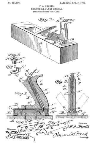
Figure 1 is a perspective view showing the application of my handle to a plane. Fig. 2 is a detail vertical sectional view through the handle. Fig. 3 is a section on the line 3 3 of Fig. 2. Fig. 4 is a detail perspective view of a rocker-plate. Fig. 5 is a detail perspective view of a block adapted to support the rocker-plate. Figs. 6 and 7 are detail perspective views of a tubular nut and a washer-plate, respectively.
In the drawings, A represents a plane of any make or construction having on its upper face a boss B. A block C, semicylindrical in cross-section, is cut out on its under straight face, as shown at C’, to fit over the boss B. The block is apertured at C2 for the reception of countersunk screws and at the ends is notched, as shown at C3. Radially-arranged apertures are formed therein, as shown at C3, said apertures or bores being parallel to the ends of the block. A rocker-plate D has a flat smooth upper face and is curved on its under face to fit the curvature of the block C, as shown in Fig. 3, and the plate has also depending end portions which carry inwardly-extending pintles D2, adapted to engage the notches C3 of the block C. The plate is recessed on one longitudinal edge, said recesses being adapted to aline with the apertures C2 of the block C, whereby access is had to the screw-heads for the purpose of tightening or removing the screws connecting the block C to the boss B. The plate D is also apertured at D3 to receive the lower end of a sleeve F, hereinafter described, the aperture D3 being placed so that it can be brought successively in alinement with the bores C4 as the plate is rocked on the block C. The handle E is mounted on the plate D, to which it is secured by a suitable screw and placed longitudinally in the handle, and downwardly and rearwardly inclined is a metal sleeve F, threaded internally adjacent its upper end and having its lower end in engagement with the aperture D3 of the plate D, the said lower end extending below the handle E and into aperture D. On the upper end of the handle is placed a washer or plate G, having a circular opening G’ in alinement with the upper open end of the sleeve F and carrying on one side two parallel upward arms G2, between which a lever J is pivoted intermediate its ends.
A tubular nut having a head H, threaded shank portion H’, and bore H2 serves to lock the washer or plate G to the handle, and a plunger-rod J’, which works in the sleeve F, projects through the bore H2 of the nut and is pivotally connected at its upper end to the lever J. Adjacent its lower end the plunger is bent or curved, as shown at J2, and this bent portion engages the apertures or bores C4 of the block C, working through the aperture D3 of the plate D. A coil-spring K is placed in the sleeve F around the plunger-rod J’ and bears at its upper end against the inner end of the tubular nut and at its lower end on a stop-pin K’, carried by the plunger-rod J’.
By means of the above construction a very substantial handle is formed which can be adjusted laterally with respect to the plane and locked by the plunger-rod J’ in its adjusted position.
Having thus fully described my invention, what I claim as new, and desire to secure by Letters Patent, is —
1. A device of the kind described oornprising a semicylindrical block having a plurality of radial bores therein, a rocker-plate pivotally connected to each end of the block and adapted to rock laterally thereon, said plate having an aperture adapted to aline with the bores of the block, a plane-handle carried by the plate, a sleeve having its inner end in engagement with the aperture of the plate, a plunger-rod working in the sleeve, and means for operating the plunger-rod.
2. The combination with a plane, of a semicylindrical block carried thereon and having radial bores parallel to the ends of the block, a plate curved on its under face and having inwardly-extending pintles at its ends, the block having notches at the ends to receive the said pintles, the said plate having an aperture adapted to aline with the bores of the block, a handle carried by the plate, a sleeve downwardly and rearwardy inclined and carried by the handle, the lower end of said sleeve engaging the aperture of the plate, and a plunger-rod working in the sleeve and curved adjacent its lower end, the said lower portion of the rod working through the aperture of the plate and engaging one of the said bores of the block.
3. The combination with a plane, a block semicylindrical in cross-section carried by the plane, and having apertures adapted to receive screw-heads and notched at the ends, the said block having a plurality of radial bores, a plate flat on its upper face and curved on its lower face, and having downwardly-extending ends, pintles carried by the said ends adapted to engage the notches of the block, the said plate being recessed on one side edge, said recesses alining with the screw-receiving apertures of the block, and the plate being apertured in alinement with the radial bores of the block, a handle carried by the plate, and a plunger working through the handle and adapted to engage the bores of the block as and for the purpose set forth.
4. The combination with a plane, a block having radial bores, a plate having the pivot-pins at each end in engagement with the ends of the block and apertured in alinernent with the bores, a handle carried by the plate, an inclined sleeve passing longitudinally through the handle, a plate on the upper end of the handle apertured to aline with the upper end of the sleeve, vertical arms carried by the plate, a lever pivoted between said arms, a headed, tubular screw passing through the plate on the handle and into the sleeve, the aperture of the plate and the interior of the upper end portion of the sleeve being threaded, a plunger-rod curved adjacent its lower end and having its upper end portion projecting through the tubular nut and pivotally connected to the lever, a pin on the plunger, and a coil-spring in the sleeve between the pin and inner end of the nut, as and for the purpose set forth.
FRED ALLEN SHONTZ.
Witnesses:
D. B. CRONIN,
F. CHRISTIANSON.