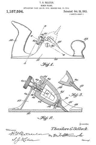
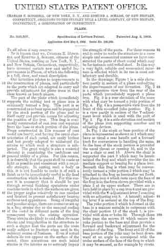
No. 1,181,004 – Bench Plane (George W. Harvey) (1916)

[paiddownloads id=”711″]1181004


UNITED STATES PATENT OFFICE.

_________________

GEORGE W. HARVEY, OF JASPER, MISSOURI.

BENCH-PLANE.

_________________

1,181,004. Specification of Letters Patent. Patented Apr. 25, 1916.
Application filed July 22, 1915. Serial No. 41,306.

_________________

To all whom it may concern:

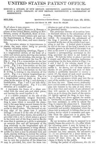
Be it known that I, GEORGE W. HARVEY, citizen of the United States, resident of Jasper, in the county of Jasper and State of Missouri, have made a certain new and useful Invention in Bench-Planes; and I declare the following to be a full, clear, and exact description of the same, such as will enable others skilled in the art to which it appertains to make and use the invention, reference being had to the accompanying drawings, and to letters or figures of reference marked thereon, which form a part of this specification.

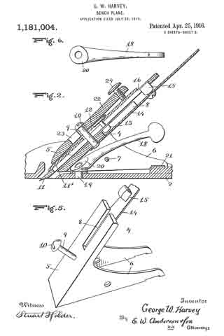
Figure 1 is a side view of the invention. Fig. 2 is a section on the line 2–2, Fig. 3. Fig. 3 is a section on the line 3–3, Fig. 1. Fig. 4 is a section on the line 4–4, Fig. 1. Fig. 5 is a detail perspective view of the bit iron holder. Fig. 6 is a detail top plan view of the adjusting lever.

The invention has relation to bench or carpenters’ planes, and it consists in the novel construction and combination of parts, as hereinafter set forth.

In the accompanying drawings, illustrating the invention, the numeral 2 designates the stock, having side flanges 3, 3, and 4 is the bit iron holder, having an incline 5 and lower side flanges 6, 6, pivoted to the flanges of the stock by a strong cross-pin 7. The bit holder has in its incline a slot 8, open at its upper end, and is provided with a stud 9, projecting upwardly at right-angles to the incline and having a head 10 at its upper end.

Resting upon the bit iron holder incline is the bit iron 11, a cap iron 11′ having therein a slot 12, of keyhole form, adapted to engage the head of the stud, when the bit and cap irons will slide downwardly to position, the contracted portion of the slot engaging the shank of the stud. Projecting from the lower wall of the bit iron, intermediately of its length, is a stud 13, fitting within the slot of the incline. An upwardly projecting, inclined spring arm 14 is secured at its lower end to the lower wall of the incline, and carries intermediately of its length an upwardly projecting squared stud 15, engaging a squared slot or seat 16 of the bit iron.

A wedge 22 has, intermediately of its length, a keyhole slot 23 therein, engaging over the headed end of the stud 9, said wedge having at its upper end a screw 24, having contact with the upper portion of the cap iron, to press said iron, with the bit iron, downwardly against the incline of the bit iron holder and bind it securely in place thereupon.

Located below the spring arm, about midway between the same and the floor of the stock, is a rearwardly projecting inclined lever 18, having at its lower end a pivot upon a vertical pin 19 of the stock, said lever having at its lower end an upper cam surface 20, against which the lower wall of the incline bears, so that when the lever is moved to one side or the other, the cam will engage the bit iron holder and move the same upwardly or allow the same to move downwardly, upon the cross~pin as a pivot, the bit iron holder and bit iron carried thereby rocking upon said cross-pin, to adjust the cutting edge upwardly or downwardly and thereby vary the thickness of the shaving, said lever being easily worked by one finger, without changing the grip upon the handle, so that delicate adjustments, to vary the thickness of the shaving, may be conveniently made. As the bit iron holder and bit iron are adjusted as stated, to vary the thickness of the shaving, a transverse spring 21, located beneath the rear portions of the flanges 6 of the bit iron holder, is put under tension, this transverse spring acting to press the bit iron holder in contact with the cam, and accomplishing the downward recking movement of the bit.

What I claim is:

1. In a plane, a stock, a bit iron holder pivoted to said stock, a bit iron upon said holder, a pressure spring for said holder and said bit iron in rear of said pivot, and a transversely movable adjusting lever having a vertical fulcrum pin connection with said stock and a cam end in contact with said holder forward of said pivot.

2. In a plane, a stock having side flanges, a bit iron holder having side flanges, a bit iron upon said holder, a pivotal cross-pin connecting the flanges of said stock and said holder, a pressure spring for said holder and said bit iron in rear of said cross-pin, and transversely movable adjusting lever having a vertical fulcrum pin connection with said stock and a cam end in contact with said holder forwardly of said cross-pin.

3. In a plane, a stock, a bit iron holder pivoted to said stock, a bit iron upon said holder, a pressure spring for said bit iron and said holder in rear of the pivot thereof, In testimony whereof I affix my signature, and a transversely movable rearwardly projecting lever having at its lower end a vertical fulcrum pin connection with the stock and an upper cam surface bearing against the said holder forwardly of the pivot thereof.

GEORGE W. HARVEY.

Witnesses:
LEIGH I. DODWELL,
ADOLPH McGEE.

_________________

Copies of this patent may be obtained for five cents each, by addressing the “Commissioner of Patents, Washington, D. C.”
_________________

No. 1,157,594 – Bench Plane (Theodore G. Selleck) (1915)

[paiddownloads id=”705″]1157594


UNITED STATES PATENT OFFICE.

_________________

THEODORE G. SELLECK, OF CHICAGO, ILLINOIS, ASSIGNOR OF ONE-HALF TO JOHN L. DEPPEN, OF CHICAGO, ILLINOIS.

BENCH-PLANE.

_________________

1,157,594. Specification of Letters Patent. Patented Oct. 19, 1915.
Application filed January 26, 1914. Serial No. 814,479. Renewed March 17, 1915. Serial No. 15,055.

_________________

To all whom it may concern:

Be it known that I, THEODORE G. SELLECK, a citizen of the United States, residing at Chicago, in the county of Cook and State of Illinois, have invented certain new and useful Improvements in Bench-Planes, of which the following is a specification.

This invention relates to bench-planes, and its object is to provide a structure which permits the bit to be quickly and easily removed for sharpening, without disturbing the adjusting means thereof.

The invention also has for its object to provide novel and improved means for adjusting the bit.

Other objects and advantages of the invention will be pointed out in the detailed description appearing hereinafter, and in order that the same may be better understood, reference is had to the accompanying drawings, in which —

Figure 1 is a side elevation of a bench plane constructed in accordance with the present invention; Fig. 2 is a longitudinal section on the line 2–2 of Fig. 4; Fig. 3 is a sectional detail showing a slightly modified form of bit; Fig. 4 is a section on the line 4-4 of Fig. 1; Fig. 5 is a section on the line 5–5 of Fig. 1, and Fig. 6 is a section on the line 6–6 of Fig. 4.

Referring specifically to the drawing the stock of the plane is of conventional form, the same comprising a sole 10, side or check-pieces 11, a rear hand grip 12 and a forward knob 13. The sole has a slot 14 through which the bit 15 protrudes.

The bit 15 is carried by a member 16 which is pivotally mounted between the side pieces 11 in a manner to be presently described. By thus pivoting the bit carrier the same may be rotated to take the bit out of the slot 14 as shown by dotted lines in Fig. 1, the bit then pointing upward and being free of the side pieces, in which position it is readily accessible for the purpose of removal. The axis of rotation of the bit carrier is transverse of the stock. The bit carrier 16 tapers toward the end which carries the bit 15, said end having a dovetailed transverse groove 17 in which the bit seats and is held, the rear portion of the bit being shaped to fit in the groove.

The following clamping means for the bit 15 is provided: In the under side of the bit carrier 16 is a threaded aperture to receive a screw 18. This aperture is so located that it intersects the inner end of the groove 17, thus allowing a portion of the back of the bit to extend into the aperture, at the place where the beveled side of the screw head 19 seats, the aperture being countersunlr to accommodate said screw head. By working the screw inward, the beveled side of the head is forced against the back of the bit, and the bit is forced forward to a rigid seat in the groove. The bit can be readily removed by sliding it along the groove, after backing the screw.

Fig. 3 shows a slightly modified form of bit, its inner end having a shoulder 20 which abuts against the end of the bit carrier 16. The bit carrier 16 is a hollow casting having side openings 21. The sides of the bit carrier are flat and parallel, and its width is such that it has a small amount of side play between the side pieces 11. The bit carrier is carried by a yoke, the side arms 22 of which latter seat in longitudinal grooves 23 in the sides of the bit carrier. The connecting bar 24 of the yoke extends across and in spaced relation with the rear end of the bit carrier, or that end which is opposite the end carrying the bit 15. The bar 24 has, midway between its ends, an aperture in which is held an adjusting screw 25 which is threaded through a block 26 carried by the bit carrier, the latter having an aperture 27 to accommodate the inner end of the screw. The screw is held against travel in the direction of its length by its head 27a and a collar or washer 28 located, respectively, on opposite sides of the bar 24. Thus, it will be seen that when the screw is operated, the bit carrier is moved baclr and forth between the arms 22 to regulate the degree of protrusion of the bit through the slot 14.

The yoke is pivoted to the side pieces 11, which provides the hereinbefore described pivotal support for the bit carrier 16. The pivotal connection is made by pivot screws 29 passing through the side pieces and threaded into the arms 22 of the yoke. The heads 30 of the pivot screws are countersunk in the side pieces, and their shanks are devoid of threads where they pass through the side pieces, which enables the bit carrier to be swung without causing the pivot screws to tighten up.

The block 26 seats against the rear end of the bit carrier 16 between outstanding spaced ribs 31 and 32 on the latter, and it is pivoted at one end so that it may swing outward from the end of the bit carrier. The pivotal connection is made by a pin 33 passing through the block and held at its ends in the ribs 31 and 32. The free end of the block is shaped to form a half nut, the thread 34 of which fits in the groove of a worm 35 seating in a recess in the end of the bit carrier, and mounted on a pivot screw 36 carried by the latter. The worm carries a small projecting finger-piece 37 for operating the same.

Upon turning the worm 35 in one direction, by means of the finger-piece 37, the block 26 swings outward from the bit carrier 16, as shown by dotted lines in Fig. 4, and it is swung back toward the bit carrier upon turning the worm in the opposite direction. This movement of the block reults in giving the bit carrier a sidewise tilt to line up the slot 14.

In order to prevent the bit carrier 16 from rocking when the tool is in use, a stout spring latch 38 is provided, the same being secured to the sole 10 and having its free end offset and shaped to snap under the bar 24. When the latch is in holding position, the rear end of the bit carrier cannot swing downward, and it is prevented from swinging upward by the bit 15 engaging the rear wall of the slot 14. Upon disengaging the latch from the yoke bar, the bit carrier may be swung to the dotted line position shown in Fig. 1, for the purpose stated hereinbefore.

I claim:

1. A bench-plane comprising a stock having side-pieces, a yoke pivotally mounted between the side-pieces, a bit carrier carried by the yoke and adjustable in the direction of its length, and means for locking the yoke.

2. A bench-plane comprising a stock having side-pieces, a yoke pivotally mounted between the side-pieces, a bit carrier carried by the yoke, an adjusting screw carried by the yoke and having a threaded engagement with the bit carrier, and means for locking the yoke.

3. A bench-plane comprising a stock having side-pieces, a yoke pivotally mounted between the side-pieces, a bit carrier having longitudinal side grooves, in which the yoke arms seat, means for adjusting the bit carrier in the direction of its length, and means for locking the yoke.

4. A bench-plane comprising a stock having side-pieces, a yoke pivotally mounted between the side-pieces, a bit carrier carried by the yoke and adjustable sidewise and in the direction of its length, and means for locking the yoke.

5. A bench-plane comprising a stock having side-pieces, a yoke pivotally mounted between the side-pieces, a bit carrier carried by the yoke, a pivoted member carried by the bit carrier, an adjusting screw carried by the yoke and having a threaded engagement with the pivoted member, a worm carried by the bit carrier and having a threaded engagement with the free end of the pivoted member, and means for locking the yoke.

6. A bench-plane comprising a stock, a bit carrier, a support for the bit carrier carried by the stock, a pivoted member carried by the bit carrier, an adjusting screw carried by the support and having a threaded engagement with the pivoted member, and a worm carried by the bit carrier, and having a threaded engagement with the free end of the pivoted member.

In testimonv whereof I affix my signature in presence of two witnesses.

THEODORE G. SELLECK.

Witnesses:
S. J. LEHRER,
H. W. BATCHELOR.

_________________

Copies of this patent may be obtained for five cents each, by addressing the “Commissioner of Patents, Washington, D. C.”
_________________

No. 1,021,369 – Plane (Thomas A. Manley) (1912)

[paiddownloads id=”681″]1021369


UNITED STATES PATENT OFFICE.

_________________

THOMAS A. MANLEY, OF AUBURN, NEW YORK, ASSIGNOR TO OHIO TOOL COMPANY, OF AUBURN, NEW YORK, A CORPORATION OF NEW YORK.

PLANE.

_________________

1,021,369. Specification of Letters Patent. Patented Mar. 26, 1912.
Application filed January 18, 1912. Serial No. 671,879.

_________________

To all whom it may concern:

Be it known that I, THOMAS A. MANLEY, a citizen of the United States, residing at Auburn, in the county of Cayuga and State of New York, have invented certain new and useful Improvements in Planes, of which the following is a specification.

This invention relates to improvements in planes, and has for its object to provide novel, simple, convenient and effective means for adjusting the plane-frog longitudinally for facilitating the setting of the bit or plane iron in different positions in the throat of the plane body.

A further object is to provide novel and simple means for locking the frog after the same has been adjusted. And a particular object of the invention is to provide convenient and effective means for adjusting and locking the frog without disturbing the plane iron and related parts.

The various features and parts and the operation of the same, will be fully set forth in the detailed description which follows, illustrated in the accompanying drawing, and then particularly pointed out in the claims.

Figure 1 is a side elevation and part section of my complete plane. Fig. 2 is a horizontal section, taken on line 2–2 of Fig. 1. Fig. 3 is a vertical cross-section, taken on line 3–3 of Fig. 2. Fig. 4 is a horizontal section similar to Fig. 2; showing a modification of the locking and adjusting means. Fig. 5 is a vertical cross-section, taken on line 5–5 of Fig. 4.

Similar characters of reference designate like parts throughout the several views.

In the drawing, 2 represents the body of the plane, 3 the sole, 4 the throat or mouth, and 5 the cheeks or lateral guards which are formed integral with the body. The rear side or edge of the throat 4 is formed sharp and thin, and then the metal inclines upwardly and rearwardly at a slight angle for forming a smooth bearing surface 6 which extends across the upper side of the sole 3, to receive a correspondingly formed forwardly projecting portion 7 of the frog 8. The frog 3 consists of an irregularly shaped casting or part having a rearwardly and upwardly inclining top surface 9, for receiving and supporting the plane iron or bit 10, and having a substantially plain horizontal bottom 11, which bears and slides upon a comparatively long elevated step or portion 12, preferably an integral part of the body of the plane. The elevation or seat 12 is disposed a short distance rearwardly of the inclined bearing 6, and its top surface lies in a higher plane than the said bearing. The under side of the frog is correspondingly shaped, so that when the bottom 11 of the frog rests upon the elevation 12, the forward end 7 approaches close to the sloping surface 6. 13 represents like inwardly facing angular ribs or tongues formed horizontally on the cheek pieces 5, directly above the opposite side-edges of the elevated bearing 12, and 14 represents hollow corners or grooves formed in the opposite bottom corners of the frog, the said hollow corners preferably being formed right-angled, so as to clear the ribs 13 when the frog is moved to and fro over the body of the plane. The tongues or ribs 13 are triangular in cross-section, and preferably extend the length of the elevated bearing 12, and they are disposed parallel to said bearing, so that the frog, when operatively connected with the tongues, may be freely moved forward and backward in a true and level plane. The tongues 13 are of sufficient length and strength to effectually hold the frog from chattering while the plane is in operation.

To hold the frog 8 in place on the base 2, and yet allow said part to be freely moved to and fro for adjusting the cutting-blade or bit 10 relatively to the throat 4, the underside of the frog is provided with a broad transverse dove-tail groove or slot 15, in which is operatively fitted a pair of correspondingly shaped keys or locking members 16–17. The keys 16–17 are disposed end to end, in the slot or way 15, and their combined length is slightly less than the breadth of the bearing surface 12 beneath the tongues or guides 13, the outer ends of the keys 16–17 then project beyond each side of the bottom of the frog, as shown in Figs. 2 and 3. The outer ends of the keys 16–17 are beveled to correspond to the under-cut sides of the tongues 13 (see Fig. 3). The abutting ends of the keys 16–17 are provided with transverse concaves 18, the said concaves tapering toward the forward end of the frog.

19 represents a set-screw having a tapering point 19′ extending beyond the threads, the said point being tapered to correspond to the concaves 18 of the keys. The set-screw 19 passes through a threaded hole 20 formed in the rear portion of the frog (see Figs. 1 and 2), the hole 20 being arranged to bring the set or locking screw 19 into coincidence with the abutting ends of the keys 16–17. When the keys 16–17 are brought together, the opposite concaves 18 form a tapering hole corresponding to the tapering point 19′ of the set-screw. In practice, the length of the tapering end of the screw 19 is such that its point 19′ normally projects part way into the tapering hole 18 between the ends of the keys. To lock the frog in any adjusted position the wedge screw 19 is driven inwardly until its tapering end 19′ spreads and forces the keys 16–17 in opposite directions against the beveled under-sides of the tongues or ribs 13 (see Fig. 3). Any desired pressure or tension may be produced by means of the wedging of the screw 19 between the abutting ends of the keys 16–17. The said keys are preferably broad enough to insure a firm bearing beneath and against the tongues 13, and will hold the frog rigidly in place. By the provision of the beveled ends of the keys 16–17, when the screw 19 is driven inwardly for spreading said keys, they exert a downward pressure which forces and holds the frog rigidly against the bearing surfaces of the elevated seat 12. When the keys are made as shown in Figs. 1, 2 and 3, they are not liable to wear seats in the under-side of the ribs 13, which will interfere with the line and accurate adjustment of the frog. In practice the key 16 is made longer than the key 17, so as to bring the abutting ends (18) to one side of the longitudinal center of the body 2. Under this arrangement the screw 19 may be readily manipulated without interference by the handle 21 or the bit adjusting-screw 22.

To assemble the frog and plane body, the frog is inserted between the cheeks 5 just forwardly of the tongues 13, and when brought to the proper position the projecting beveled outer-ends of the keys 16–17 may be entered underneath the tongues 13, after which the frog may be moved rearwardly until brought to the desired position. In constructing the plane body and the frog, the tongues 13 and the hollow-corners 14 are arranged so that the bottom 11 of the frog will rest firmly upon the upper surface of the elevated seat 12.

To adjust the frog to and fro longitudinally, I provide an adjusting screw 25 which enters a threaded hole 26 in the rear side of the frog 8 above the bottom 11. The screw 25 is preferably positioned at one side of the longitudinal center of the plane, so as to facilitate adjusting the frog without interference by the handle 21 or other parts of the plane. The screw 25 is held from longitudinal movement by means of a yoke 27 which forms the upright arm of an L-shaped bracket 28 which is mounted upon the upper side or face of the sole 3, by means of a screw or pin 29. The screw 25 has a circumferential groove 25′ to receive the yoke 27. When the screw 25 is turned in either direction by hand or by means of a screw-driver, it will move the frog to and fro longitudinally on the base 2. The provision of the guide tongues 13 and the corresponding beveled keys 16–17 will prevent vertical movement of the frog, as well as, lateral and longitudinal rocking of said part relative to the base, and this arrangement also insures the smooth, free and true horizontal movement of the frog on the elevated bearing surface 12. The provision and arrangement of the tongues 13 and the locking keys or members 16–17 will also effectually obviate the chattering of the bit when the plane is operated over hard or burly wood.

Figs. 4 and 5 illustrate a modification of the adjusting and locking parts, and also a slight modification of the form and arrangement of the bottom of the frog 8′. The lower side corners of the frog 8′ are provided with annular grooves 14′, which conform to the shape of the tongues 13′ (see Fig. 5). The locking means comprise apair of like round keys or pins 30 and 31 which are loosely disposed in a hole 32 which passes transversely through the lower portion of the frog. The outer ends of the pins or keys 30 and 31 are beveled to correspond to the under-out sides of the guide ribs 13′, and their combined length is slightly less than the distance between the ribs 13′, for permitting endwise adjustment, the same as the keys 16–17. The keys 30 and 31 are preferably the same length, and their inner ends meet at the transverse center o-f the frog. The abutting ends 33 of the keys 30–31 are formed concave, and taper forwardly, similar to the construction shown and described for the keys 16–17. To lock the frog 8′ from longitudinal movement, I provide a screw 34 which enters a threaded hole 35 formed centrally in the rear-part of the frog 8′. The inner end of the screw 34 is provided with a tapering point 36, which is arranged to enter the tapering concaves arranged in the abutting ends of the keys 30 and 31 for wedging them apart. When the screw 34 is driven inwardly the point 36 spreads the keys 30–31 and forces said keys laterally for tightly engaging the underside of the ribs 13′. When the screw 34 is driven tightly between the keys, the frog 8′ will be held from longitudinal movement. The arrangement of the dove-tail tongues 13′ and the similar grooves 14′ is such that, the frog cannot be moved vertically until it is withdrawn free from the ribs. To adjust the frog 8′ to different positions longitudinally, the screw 34 is first loosened up, and then the frog may be shifted to and fro, and set in the desired position, by hand.

The plane iron or bit 10 is provided with the usual guard plate 37, and is held in place by a cap 38, which is fitted with the usual clamping part 39.

40 represents a screw carried by the frog for engaging the cap 38. The adjusting screw 22 is employed for shifting the plane iron longitudinally on the frog, and a lever 41 is employed for adjusting the plane iron laterally.

The locking means comprising the keys and the wedge screws are extremely simple, yet affording powerful means for locking the frog to the frame. When these parts are properly made and assembled, but a slight movement of the screws 19 and 34 in either direction will effect the rigid locking or the unlocking and freeing of the frog. The broad keys 16–17 cooperating with the side ribs 13 tend to steady the frog during its forward and backward movements. The disposition of the screws 19 and 25 at or near the sides of the plane render the locking and adjusting parts conveniently accessible, and in view of the location and arrangement of these parts the locking and adjusting of the frog may be accomplished without disturbing the plane-iron or any other part.

Having thus described my invention what I claim as new and desire to secure by Letters Patent, is —

1. In a plane, the combination with a sole having a throat and an elevated seat arranged rearwardly of said throat, of a frog having a plane bottom adapted to rest and slide upon said seat, said frog having longitudinal grooves formed in its opposite bottom corners, a pair of angular tongues carried by the body of the plane, said tongues received by said grooves, and adjustable means carried by said frog adapted to engage said tongues for guiding and locking said frog.

2. In a plane, the combination with a sole having a throat and an elevated seat arranged rearwardly of said throat, of a frog having a plane bottom adapted to rest and slide upon said seat, said frog having longitudinal grooves formed in its opposite bottom corners, a pair of angular tongues carried by the body of the plane, said tongues received by said grooves, adjustable means carried by said frog adapted to engage said tongues for guiding said frog, and a screw cooperating with said means for locking said frog rigidly to the elevated seat.

3. In a plane, the combination with a sole having a throat and an elevated seat arranged rearwardly of said throat, of a frog having a plane bottom adapted to rest an slide upon said seat, said frog having longitudinal grooves formed in its opposite bottom corners, a pair of angular tongues carried by the body of the plane, said tongues received by said grooves, adjustable means carried by said frog adapted to engage said tongues for guiding and locking said frog, and a swivel-screw for adjusting said frog to different positions on said sole.

4. In a plane, the combination with a sole having spaced cheek pieces and having an elevated seat between said cheek pieces, of horizontal guide-ribs formed on the inner sides of said cheek pieces above and parallel to the said seat, a frog having a plane bottom slidable upon said seat, the opposite lower corners of said frog cut away to clear said ribs, a pair of keys disposed end to end in a transverse slot formed in the bottom of said frog, said keys having their outer ends beveled to pass under and to engage said ribs, and a tapering screw for spreading said keys apart for locking the frog to said ribs.

5. In a plane, the combination of a sole having a transverse throat and an inclined bearing adjacent the throat, and having an elevated seat adjacent the inclined bearing, triangular ribs formed above and parallel to the said elevated seat, a frog having a plane bottom surface adapted to engage and slide upon said elevated seat between said ribs, said frog having portions out-away for clearing said ribs, and a pair of transversely movable keys carried by said frog adapted to engage said ribs for guiding and also for locking said frog.

6. In a plane, the combination of a frame comprising a sole and spaced cheek pieces, a raised seat formed on the sole between the cheek pieces, an inwardly facing tongue carried by each cheek piece disposed horizontally above said raised seat, said tongues having their facing sides under-cut, a frog slidable on the said raised seat between the said tongues, but free from said tongues, transversely movable keys carried by the frog having beveled outer ends adapted to slide beneath the under-out sides of said tongues for guiding said frog when moved to and fro on said seat, and a wedge-screw carried by said frog adapted to force and hold said keys against said tongues for locking said frog from movement in any direction.

7. In a plane, the combination with a body having an integral elevated seat lying between like cheeks projecting upwardly on its opposite sides, and ribs formed on the inner sides of said cheeks and overhanging said elevated seat, said ribs disposed parallel to the said elevated seat and also to the sole of the body, of a frog having a plane bottom surface adapted to engage and slide upon the said elevated seat, said frog having its opposite bottom corners. cut-away to receive said ribs, and means carried by said frog adapted to engage said ribs for holding said frog from vertical movement.

8. In a plane, the combination of a frame comprising a sole and spaced cheek pieces, a raised seat formed on the sole between the cheek pieces, an inwardly facing; tongue carried by each cheek piece disposed horizontally above said raised seat, said tongues having their facing sides under-cut, a frog slidable on the said raised seat between the said tongues, but free from said tongues, transversely movable keys carried by the frog adapted to slide beneath the under-cut sides of said tongues for guiding said frog when moved to and fro on said seat, a wedge-screw carried by said frog adapted to force and hold said keys against said tongues for locking said frog from movement in any direction, and a swivel-screw for adjusting said frog to different positions in the said frame.

9. In a plane, the combination with a body having an integral elevated seat, said body having like cheeks projecting upwardly on its opposite sides, and ribs formed on the inner sides of said cheeks and overhanging said elevated seat, said ribs disposed parallel to the said elevated seat and also to the sole of the body, of a frog having a plane bottom surface adapted to engage and slide upon the said elevated seat, said frog having its opposite bottom corners cut-away to receive said ribs, means carried by said frog adapted to engage said ribs for guiding said frog during its longitudinal movements, and means for adjusting said frog to different positions on said elevated seat.

10. In a plane, the combination of a body having vertically disposed lateral guards, ribs carried by the inner faces of said guards, said ribs arranged parallel to the sole of said body, an elevated step disposed beneath and parallel to said ribs, a frog having a substantially flat bottom adapted to rest and slide upon said elevated step, the opposite sides of said frog cut-away to clear said ribs, transversely disposed keys carried by said frog, the outer ends of said keys projecting beyond said frog adapted to engage the under-cut edges of said keys for holding said frog firmly upon said step, said keys and said ribs cooperating for guiding said frog when moved to and fro on said body, and a wedge-screw carried by said frog adapted for spreading said keys for rigidly locking said frog to the said ribs.

11. In a plane, the combination of a sole having a transverse throat and an inclined bearing adjacent the throat, and having an elevated seat adjacent the inclined bearing, triangular ribs disposed above and parallel to the said seat, a frog having a plane bottom surface adapted to engage and slide upon said seat between said ribs, a pair of keys carried by said frog adapted to engage said ribs for guiding and also for locking said frog, and a screw for adjusting said frog to different positions relative to said throat.

In testimony whereof I affix my signature in presence of two witnesses.

THOMAS A. MANLEY.

Witnesses:
G. W. BAYNON,
N. L. CASEY.

_________________

Copies of this patent may be obtained for five cents each, by addressing the “Commissioner of Patents, Washington, D. C.”
_________________

No. 987,081 – Plane (Edmund A. Schade) (1911)

[paiddownloads id=”678″]987081


UNITED STATES PATENT OFFICE.

_________________

EDMUND A. SCHADE, OF NEW BRITAIN, CONNECTICUT, ASSIGNOR TO THE STANLEY RULE & LEVEL COMPANY, OF NEW BRITAIN, CONNECTICUT, A CORPORATION OF CONNECTICUT.

PLANE.

_________________

987,081. Specification of Letters Patent. Patented Mar. 14, 1911.
Application filed December 27, 1910. Serial No. 599,481.

_________________

To all whom it may concern:

Be it known that I, EDMUND A. SCHADE, a citizen of the United States, residing at New Britain, county of Hartford, State of Connecticut, have invented certain new and useful Improvements in Planes, of which the following is a full, clear, and exact description.

My invention relates to an improved frog adjustment for a bench plane, whereby the frog, which is the means for supporting the plane iron, may be readily adjusted to and fro, and which, when locked in position, is rigidly held in such a manner as to reduce to a minimum any chance of slippage or displacement.

In the drawings, Figure 1 is a longitudinal section of a plane showing my improved adjustment. Fig. 2 is a section on the plane of the line x–x, Fig. 1, looking from left to right. Figs. 3, 4 and 5 are detail views. Fig. 6 is a longitudinal section of part of a plane of slightly modified construction from that shown in Fig. 1, my invention being applied thereto. Fig. 7 is a cross section on the line y–y of Fig. 6, looking from right to left. Fig. 8 is a longitudinal section of a part of a plane of another modified form. Fig. 9 is a cross section on the line z–z Fig. 8, looking from left to right. Fig. 10 is a longitudinal section illustrating still another modification. Fig. 11 is a cross section thereof on the line w–w looking from right to left.

Referring to Figs. 1 to 5, 1 represents a sole of an iron bench-plane which may be, as to general details, of conventional form. 2 is a frog bearing, in this particular instance formed on an incline directly to the rear of the throat 3. 4 is a frog adjustably mounted on the support 2 for movement to and fro relatively to the throat 3. 5 is a plane iron. 6 is a cap of conventional form and by which the plane iron may be clamped to the frog 4. The invention in this case resides primarily in the means for adjustably securing the frog 4 to the frog support 2. In this instance the frog is provided with two longitudinal slots or passages 7 in which stand clamping or gripping studs 8–8. These studs are headed, the headed portions standing above the slots, the opposite ends projecting down into cavities or recesses in the support 2. Each stud is transversely recessed toward its lower end, as indicated at 9. 10 is what I will term a cam stud, there being one for each gripping stud 8. The cam studs are arranged in the support 2, suitable bores being provided therefor, the rear ends of said studs being arranged to receive a suitable tool, for example, a screw driver, the forward end of each cam stud being provided with an eccentric projection or cam 11. This cam 11 projects into the recess 9 of the respective gripping stud. 12 is a slot in the side of each cam stud. Entering from the side of the plane is a locking screw 14, the same being so arranged relatively to the slotted portion 11 of the cam stud that the forward ends of each screw 14 will engage the wall at the base of the recess 12 at one side of, or eccentric to, the axis of the cam stud.

In the operation of the parts thus far described, it will be seen that by rotating the cam stud in the proper direction, the cam 11 will engage with the wall at the lower end of the recess 9 in the gripping stud so that said gripping stud will be pulled down into firm gripping engagement with the frog 4. To give a further set to the cam and to guarantee against disengagement, the screw 14 may be turned in until its nose engages eccentrically said cam stud, tending to turn it in a direction to increase the tension of the cam on the gripping stud and also preventing any rotation of the cam stud in a reverse direction to release said gripping stud. I have found, by this means, that the frog may be very quickly and easily adjusted, and, at the same time, when locked in position, is held with exceeding rigidity.

In the other views I have shown slight modifications. For example, in Figs. 6 and 7 I have shown the frog 4a as mounted upon a support 2a having a two-point bearing for the frog. In this case as before, the frog is held by means of gripping studs 8a operated by cam studs 10a which are in turn controlled by screws 14a.

In Figs. 8 and 9 I have shown a modification in which instead of providing the gripping studs 8 for holding the frog to its seat, I have provided the frog 4b with a plate-like extension 8b which is preferably cast into the frog, so as to be a permanent part thereof, said plate 8b having passages to receve the cam ends 11b of the cam studs 10b. In this case, as previously, the side screws 14b may be employed to cooperate with the cam studs for the same purpose as before.

In Figs. 10 and 11 I have shown a modification more particularly of the construction shown in Fig. 8 in that instead of anchoring the aforesaid plate in the frog, I have anchored a similar plate in the frog support. In these views, 8c represents said plate anchored in the support 2c, and in this case the cam studs 10c are carried in passages in the rear of the frog 4c, the cam ends 11c engaging the walls of the slot in the plate 8c in the same manner as the cam ends 11b engage the walls of the slot in the plate 8b, shown in Figs. 8 and 9. Here again take-up screws are employed, the same being indicated at 14c. In this case the take-up screws are carried by threaded bores in the sides of the frog, suitable windows or clearance openings 15 being provided in the cheek pieces of the plane to permit a screw driver to be entered sufficiently to engage the slotted ends of said screws 14c for the purpose of operating the same.

In both forms of devices shown in Figs. 8 to 11, a suitable clearance space is provided for the plates 8b and 8c respectively whereby there may be a relative movement between said plate and the part carrying the cam screw. In these cases, the cam ends 11b and 11c respectively should be of sufficient length to engage the plates 8b and 8c respectively in all of the various positions of adjustment.

What I claim is:

1. In a plane, a main body portion having a throat therein, a frog support at the rear of said throat, a frog adjustable to and fro thereon, a locking means for holding said frog in different positions of adjustment comprising a clamping member operatively engaged with one of said parts, means for operating said clamping member carried by the other part and comprising a rearwardly projecting cam stud coacting with said clamping member, and a lock and tightener for said cam stud, said lock and tightener comprising a laterally projecting exposed screw engaging said cam stud in a direction to turn the same as said lock and tightener is advanced.

2. In a plane, a main body portion having a throat therein, a frog support at the rear of said throat, a frog adjustable to and fro thereon, a locking means for holding said frog in different positions of adjustment comprising a clamping member operatively engaged with one of said parts, means for operating said clamping member carried by the other part and comprising a rearwardly projecting cam stud coacting with said clamping member, a lock for said cam stud, said lock comprising a laterally projecting exposed screw, and a shoulder on one side of said cam stud eccentric thereto, said screw engaging said eccentric shoulder and pressing against the same in a direction to turn said cam stud so as to more tightly engage the clamping member.

3. In a plane, a body portion having a throat, a frog support at the rear of said throat, a frog adjustable to and fro on said support and relatively to said throat, a clamping member carried by said frog and projecting into said support, said support having a recess therefor, a cam stud carried in said support and exposed at its rear end, an eccentric pin extension at the forward end of said stud eccentrically engaging said clamping member, and a lock screw for engaging said clamping stud at one side and arranged laterally thereto.

4. In a plane, a body portion having a throat, a frog support at the rear of the throat, a frog mounted for adjustment to and fro on said support, said frog having a fore and aft slot therein, a clamping stud passing downwardly through said slot into said support, an operating device for said clamping stud comprising a cam stud mounted in said support, an eccentric pin projection at the forward end of said cam stud eccentrically engaged with said clamping stud, and a lock for said cam stud.

5. In a plane, a body portion having a throat, a frog support at the rear of the throat, a frog mounted for adjustment to and fro on said support, said frog having a fore and aft slot therein, a clamping stud passing downwardly through said slot into said support, an operating device for said clamping stud comprising a cam stud mounted in said support, an eccentric pin projection at the forward end of said cam stud eccentrically engaged with said clamping stud, and a lock for said cam stud, said lock comprising a screw entering said frog support from the side of the plane.

6. In a plane, a body portion having a throat, a frog support at the rear of the throat, a frog mounted for adjustment to and fro on said support, said frog having a fore and aft slot therein, a clamping stud passing downwardly through said slot into said support, an operating device for said clamping stud comprising a cam stud mounted in said support and eccentrically engaged with said clamping stud, and a lock for said cam stud, said lock comprising a screw entering said frog support from the side of the plane, said screw engaging said cam stud eccentrically to rotate the same in a direction to increase the pressure on the clamping stud.

EDMUND A. SCHADE.

Witnesses:
W. J. WORAM,
H. S. WALTER.

_________________

Copies of this patent may be obtained for five cents each, by addressing the “Commissioner of Patents, Washington, D. C.”
_________________

No. 955,557 – Plane (Edmund A. Schade) (1910)

[paiddownloads id=”670″]955557


UNITED STATES PATENT OFFICE.

_________________

EDMUND A. SCHADE, OF NEW BRITAIN, CONNECTICUT, ASSIGNOR TO STANLEY RULE &
LEVEL COMPANY, OF NEW BRITAIN, CONNECTICUT, A CORPORATION OF CONNECTICUT.

PLANE.

_________________

955,557. Specification of Letters Patent. Patented Apr. 19, 1910.
Application filed November 4, 1909. Serial No. 526,204.

_________________

To all whom it may concern:

Be it known that I, EDMUND A. SCHADE, a citizen of the United States, residing at New Britain, county of Hartford, State of Connecticut, have invented certain new and useful Improvements in Planes, of which the following is a full, clear, and exact description.

My invention relates to improvements in planes.

The object of the invention is to provide a simple and effective means to facilitate the adjustment of the plane frog to and fro for the proper positioning of the cutting edge of the plane iron in the throat of the plane.

In the drawings — Figure 1 is a longitudinal section of a plane taken approximately on the plane of the line x–x of Fig. 2, certain parts being shown in elevation; Fig. 2 is a cross section of the body of the plane on the line y–y, Fig. 1, showing a portion of the plane frog in elevation; F ig. 3 is a view of the under side of the forward part of the plane frog; Fig. 4 is a plan view of that part of the body of the plane which supports the frog.

1 represents the sole of the plane body; 2 the throat therein, and 3–3 are the cheek pieces. Immediately to the rear of the throat 2 is a smooth bearing support 5 designed to receive a cooperating bearing surface 7 at the forward end of the frog 6. Still farther to the rear of the throat 2 is an elevated bearing support 8, the rear portion of which is constructed to receive and support a cooperating bearing surface 9 on the frog. The bearing supports 5–8 are spaced apart so that the frog will be supported at two different points.

10 is a longitudinally arranged guide and strengthening rib on the upper side of the sole of the plane extending rearwardly from a point at or near the throat 2.

11 is a groove or slot in the under side of the frog, the side walls of which are arranged to take a bearing upon the side walls of the rib 10 whereby said rib 10 will serve to hold the frog in correct aiinement and guide the frog in its movement to and fro, thereby avoiding any twist or lateral displacement of the frog as it is being adjusted.

12–12a are longitudinal slots in the frog, parallel with the groove 11 but somewhat to the rear of the same. These slots are arranged to receive clamping screws 13–13a respectively. The lower ends of these clamping screws take into threaded openings 14–14a respectively in the sole of the plane which openings are arranged forward of the most elevated portion of the support 8.

15 is an adjusting screw carried by the sole of the plane at the rear of and below the bearing 8. This screw has a groove 15a arranged to receive a yoke 16, which is secured to the rear of the frog. When the screw 15 is moved to and fro, it will impart a corresponding movement to the frog.

17 is the plane iron or cutter held in place on the frog by the usual cap 18.

In operation, the frog is secured in place by means of the screws 13–13a, the same being set down snugly so as to prevent accidental or unintentional displacement of the frog. The strain of these screws, as shown, comes upon an intermediate part of the frog between the supports 5–8. The plane iron and cap are then applied. The adjustment of the plane iron for the purpose of projecting or retracting the cutting edge of the same may be accomplished in any well known manner, that being immaterial to my invention. If it is found that the position of the plane iron, fore and aft, in the throat 2 should be changed, it is merely necessary to move the screw 15 in the proper direction and to the desired extent, producing thereby the desired movement and adjustment of the frog. If by chance (and it is practically impossible to prevent it) one of the screws 13 or 13a is screwed down more tightly than the other, it is obvious that any movement to and fro of the frog would tend to twist the same upon its bearing supports by reason of an abnormal drag on one side of the center line. The provision of the guide rib 10 which fits between the guide walls of the groove 11 will prevent this displacement. I have found that even though the screws 13–13a be screwed down very tightly nevertheless adjustment of the frog by means of the screw 15 alone may be readily effected, due doubtless to the smooth bearing supports 5–8 and the co-acting smooth bearing surfaces 7–9 and to the fact that there is sufficient elasticity or spring in the frog along the line of the clamping screws 13–13a to prevent the absolute locking of the frog. While the clamping engagement of the screws 13–13a is not sufficient to prevent the intentional adjustment of the frog by the screw 15, said clamping engagement is quite sufficient to prevent accidental or unintentional displacement of the frog, particularly as in this respect the guiding rib 10 and the adjusting screw 15 cooperate with the clamping screws 13–13a in the retention of the frog in any of its adjusted positions.

l am aware that heretofore separated frog supports, adjusting screws, clamping screws and reinforcing ribs are old but in the present instance I have added a new function to the reinforcing rib, viz., the guiding function, and have thereby produced a means for permitting the quick and accurate adjustment of a plane frog, which means is vastly more simple and far more effective than any adjusting means heretofore produced in that it eliminates certain parts and operations heretofore regarded as essential, simplifies the act of adjusting, and guarantees a straight line movement of the frog to and fro. ln devices of this character it is desirable that the plane iron should be in position when the adjustment of the frog is being effected. By my improvement this is possible.

It is obvious that the number of guiding ribs 10 employed may be increased, but one is sufficient, and is, indeed, preferable. It is obvious that the rib 10 may engage the side walls of the groove 11 throughout their entire length, but in the preferred form it is desirable to cut back or narrow the top of the rib to the rear of its front end, so that the active guiding part of the rib is comparatively short and close to the throat. By this arrangement a slight lateral adjustment of the extreme rear end of the frog may be had in assembling the plane, only a very slight adjustment at this point ever being required (if at all) to secure the accurate positioning of the frog on the supports 5 and 8 relatively to the throat.

In practice I accomplish the proper positioning of the frog on its support in the following manner: Before tightening up the screw which holds the fork in its place, I place the forward end of the frog in its proper position upon the rib and then swing the rear end of the frog to right or to left as may be necessary to secure perfect alinement between the frog and center line of the plane bottom. During this swinging movement the fork 16 (loose on its own fastening screw) engages the circular groove 15a. When perfect alinement is secured, I force home the screw which holds the fork, thereby securing all the parts in cooperative combination. In this way the fore and aft movement of the frog on the plane bottom is made to be in perfect alinement throughout. When the fore and aft movement is secured in this manner the front edge of the frog is always parallel to the throat of the plane. This method is found to be advantageous in practice, although it is evident that with sufficient pains the proper cooperative relations of the frog and plane bottom may be secured even if the fork were firmly fastened in the first instance.

It is evident that yoke 16 and the adjusting screw 15 may be reversed, that is to say, the yoke may be secured by a screw to the bottom of the plane and the adjusting screw be inserted in the rear of the frog, these two elements cooperating with each other in the same way, whichever one of them may be uppermost. Likewise the fork may be cast integral with the portion of which it is a part.

What I claim is:

1. A bench plane comprising a body portion having a transverse throat in the sole portion thereof, a frog support to the rear of said throat, a frog mounted thereon for adjustment to and fro, means for frictionally clamping said frog to said support, a combined guide and operating means located at and accessible at the rear of the frog for moving said frog on said support longitudinally of the plane body, and a guiding rib and groove engagement between said frog and support adjacent to the throat of the plane whereby said frog will be prevented from twisting out of correct alinement relatively to the throat as it is adjusted to and fro.

2. A bench plane comprising a plane body having a transverse throat in its sole portion, a frog support, a frog mounted thereon, means for frictionally clamping said frog to said support on both sides of the central vertical plane thereof, and intermediate its forward and rear ends a single positively operating means for adjusting said frog on said support longitudinally of said plane, and a guiding rib and groove engagement between said frog and support at the forward end of the frog and adjacent to the throat of the plane whereby the said single adjusting means will move the frog parallel with said central vertical plane regardless of difference of degree of clamping between said clamping means.

EDMUND A. SCHADE.

Witnesses:
W. J. WORAM,
I. W. CHAPMAN.

No. 955,556 – Plane (Edmund A. Schade) (1910)

[paiddownloads id=”669″]955556


UNITED STATES PATENT OFFICE.

_________________

EDMUND A. SCHADE, OF NEW BRITAIN, CONNECTICUT, ASSIGNOR TO THE STANLEY RULE
& LEVEL COMPANY, OF NEW BRITAIN, CONNECTICUT, A CORPORATION OF CONNECTICUT.

PLANE.

_________________

955,556. Specification of Letters Patent. Patented Apr. 19, 1910.
Application filed March 18, 1909. Serial No. 484,099.

_________________

To all whom it may concern:

Be it known that I, EDMUND A. SCHADE, a citizen of the United States, residing at New Britain, county of Hartford, State of Connecticut, have invented certain new and useful Improvements in Planes, of which the following is a full, clear, and exact description.

My invention relates to improvements in planes, the main object being to provide superior adjusting means.

In the accompanying drawings, Figure 1 is a longitudinal section of the body of a plane and certain parts, showing also certain other parts in side elevation, this section being taken on approximately the line W–W Fig. 2. Fig. 2 is a cross-section on the line X–X Fig. 1, looking in the direction of the arrow. Fig. 3 is a cross-section on the line Y–Y Fig. 1, looking in the direction of the arrow. Fig. 11 is a cross-section on the line Z–Z Fig. 1, looking in the direction of the arrow. Fig. 5 is a central longitudinal section of certain parts of the plane. Fig. 6 is a longitudinal section taken on the same plane as the section of Fig. 1 and showing a modiication. Figs. 7 and 8 are side elevations of companion parts. Fig. 9 is a side elevation of a modified part.

1 represents the frame of a plane provided with the usual sole and cheek pieces, and having the usual handles 2–2.

3 is a saddle mounted on the sele of the plane and preferably integral therewith. This saddle 3 furnishes a support for the frog 4, upon which is mounted the plane-iron 5, the same being secured thereto by the well known clamp 5a not necessary to describe in detail herein. The forward or cutting edge of the plane-iron 5 projects through a throat 6 in the sole of the plane. In the particular form shown, the saddle 3 is provided with a rib 7, which enters a groove in the lower end of the frog 4 and so fits the same that it operates as a guide to guarantee an accurate fore and aft movement of the frog relatively to the longitudinal axis of the plane while adjustment is being effected. The frog is suitably shaped to rest upon the saddle 3 so that it may be adjusted back and forth, thereby shifting as desired the cutting edge of the plane-iron 5 forward and back in the throat 6. The usual adjusting mechanism to vary the projection of the plane-iron may be provided, but, since the same constitutes no part of this invention, it need not be described herein.

The particular feature of invention herein disclosed relates to the adjustment of the frog, whereby the throat clearance may be varied. To accomplish the adjustment of the frog, I provide an adjusting screw 8 mounted at the rear of the saddle 3 and operating to and fro. A forked plate 9 carried by and at the rear of the frog 4 stands in an annular groove in the head of the screw 8 so that as the screw 8 is operated to and fro, it imparts a corresponding movement to the frog, provided the latter is not locked in place. To lock the latter in place, I provide a simple and effective clamping mechanism comprising (in the form shown in Figs. 1 to 4 and 6 and 7) the tubular shank 10 arranged vertically in a suitable bore in the saddle 3. As shown, two of these tubular shanks 10 are provided and each of these shanks is preferably threaded to receive a screw 10a, the shank of each screw standing in a longitudinal slot 4a in the frog 4.

11–11 are set-screws which pass into the rear of the saddle 3 so as to be easily accessible from the rear. These screws preferably have conical noses at the forward end, which pass into recesses in the side of each sleeve 10 so that when said screws 11 are advanced they will operate to force the sleeves 10 down so as to clamp the heads of the screws 10a tightly against the frog, in turn drawing the frog hard down against the saddle 3. Ordinarily, in planes of this character, it has been necessary, in order to adjust the frog, to remove the plane-iron 5. Inasmuch as the degree of throat clearance cannot be accurately and quickly determined when the plane-iron is removed, it follows that an adjusting device which is accessible and operable when the plane-iron is in place, furnishes an exceedingly valuable improvement.

By my invention all that is required is to simply loosen the screws 11–11, after which the adjusting screw 8 may be turned in a direction to advance or retract the frog to the desired extent. When the proper adjustment has been attained, the set-screws 11–11 are advanced by a screw-driver entered from the rear, until the heads of the screws 10a draw down on the frog and clamp it firmly to the saddle.

During the period of adjustment, the rib serves to guide the forward edge of the frog to and fro in exactly the proper line, thus relieving all the other parts of this burden. While of course an approximate alinement might be given by the cheek-pieces, it would require an expensive machining operation to so finish the cheek pieces and frog sides that accurate alinement, from this source, could be relied upon. By my invention the rib 7 may be cast integrally with the saddle and the groove in the lower side of the frog which rides on the rib may be quickly and easily formed so as to guarantee the maximum of perfection in adjustment at a minimum of expense and labor.

In the modification shown in Figs. 6 and 9, I provide the solid clamping stud 10b in place of the companion parts 10–10a, and in this case, instead of providing a tubular sleeve similar to 10, I provide a solid shank for the stud 10b.

I am aware that various modifications may be made, and, so long as the construction selected provides for adjustment of the frog without removing the plane-iron therefrom, I deem such modification as within the scope of the broadest of the claims herein.

What I claim is:

1. In a plane, a body portion having a sole and a throat therein, a frog support arranged at the rear of said throat and extending transversely across the sole, a frog mounted on said support, and adjustable to and fro, means for adjusting said frog comprising a screw accessible at the rear of said frog, means to secure said frog on said support comprising a clamping device projecting downwardly through the frog and into said support, a locking device comprising a screw entering said support from the rear, the forward end of said screw having a cone head, a recess in said clamping device into which said cone head may be projected, the inclined wall of said cone head engaging and forcing said clamping device in a direction to rigidly secure said frog in place.

2. In a plane, a body portion having a sole and a throat therein, a frog support arranged at the rear of said throat and extending transversely across the sole, a frog mounted on said support and adjustable to and fro, means for adjusting said frog comprising a screw accessible at the rear of said frog, means to secure said frog on said support comprising a two part clamping device projecting downwardly through the frog and into said support, a locking device comprising a screw entering said support from the rear, the forward end of said screw having a cone head, a recess in said clamping device into which said cone head may be projected, the inclined wall of said cone head engaging and forcing said clamping device in a direction to rigidly secure said frog in place, said clamping device being adjustable as to length.

EDMUND A. SCHADE.

Witnesses:
W. J. WORAM,
I. W. CHAPMAN.

No. 930,307 – Plane (Charles E. Mitchell And Edmund A. Schade) (1909)

[paiddownloads id=”664″]930307


UNITED STATES PATENT OFFICE.

_________________

CHARLES E. MITCHELL, OF NEW YORK, N. Y., AND EDMUND A. SCHADE, OF NEW BRITAIN, CONNECTICUT, ASSIGNORS TO THE STANLEY RULE & LEVEL COMPANY, OF NEW BRITAIN, CONNECTICUT, A CORPORATION OF CONNECTICUT.

PLANE.

_________________

930,307. Specification of Letters Patent. Patented Aug. 3, 1909.
Application filed May 6, 1902. Serial No. 106,200.

_________________

To all whom it may concern:

Be it known that we, CHARLES E. MICHELL and EDMUND A. SCHADE, citizens of the United States, residing at New York, N. Y., and New Britain, Connecticut, respectively, have invented certain new and useful Improvements in Planes, of which the following is a full, clear, and exact description.

Our invention relates to improvements in the construction of planes, and particularly to the parts which are adapted to carry and provide adjustment for plane irons in that class known as bench planes.

The part of the plane which immediately supports the cutting tool or plane iron is commonly termed a frog. This part is so constructed as to bear upon and be supported by the stock portion of the plane and to itself carry and provide means for adjusting the position of the iron. This frog is commonly constructed of cast iron and separate from the base or stock portion of the plane. Frogs constructed in this manner of cast metal are heavy, and having the usual characteristics of such metal, are easily broken and but poorly adapted to withstand the strains to which such a structure is subjected. The great weight is also a material element in considering the usefulness and general utility of a plane. For this reason, it is desirable that the parts shall he made as light as possible and consistent with a requisite strength. In casting such a body as this, it is not feasible to make it of such a finish as to be immediately useful in the final construction which is desired. For this reason it is necessary that it should be put through several finishing operations under machine tools in which the surfaces are given the proper angles relatively to one another and finished to present satisfactory bearing surfaces and appearance. Being of irregular and peculiar shape, there are moreover set up in a frog strains due to the unequal cooling of the metal in different parts of the frog consequent upon the casting operation. These strains are likely to and often do cause checks and irregularities in the structure to such a degree that the parts are the more easily subject to fracture when used in the ordinary course of business. Even if actual defects do not appear on the surface of the metal, there sometimes are such initial strains in the interior as to seriously impair the strength of the parts. For these reasons and in order to make the structure in a more simple and economical manner we have constructed the parts of sheet metal which may he for instance cold rolled steel. ln this way a very light, reliable and economical structure is effected which in its use is most satisfactory and durable.

ln the drawings: Figure 1 is a side elevation partly in section of a plane embodying the improvements of our invention. 2 is a perspective view from the rear of the parts which immediately support a plane iron. Fig. 3 is a rear elevation of the same with what may be termed yoke portion of Fig. 4. Fig. 4 is a perspective view from the front of this so-called yoke portion. Fig. 5 is a view partly in section of the Y-adjustment lever which is used with the part of Fig. 2. Fig. 6 is a side elevation and section of the plane iron supporting member and adjusting devices.

In Fig. I the stock or base portion of the plane is represented as shown at 1 which may have as usual a rear handle and a forward knob for convenience in handling the same. In the base of the stock portion is provided the usual throat or opening 10, and to the rear a chair or seat 13. Above the chair is supported the part 2 which may he herein termed the frog and which provides the immiediate support or bearing for a plane iron. Beneath this frog is what may be conveniently termed a yoke portion 3 which may he attached to the frog as hereinafter set forth. The plane iron 4 which rests upon the face of the frog is in the form shown provided with a plate 5 at its upper surface. These are in turn held in place by a cap iron 6 and are provided with the Y-adjustment lever 7 coacting with an adjusting nut 8. A laterally adjusting lever 9 is secured at the top of the frog.

The yoke portion 3 which is formed at the lease in a manner suitable to cooperate with the chair portion 13 of the stock 1, is provided with slots or holes 30. Through these holes pass the screws 31 which secure the yoke portion to the base and thus provide a forward and backward adjustment for the position of the frog. The front end 32 of the base portion of the yoke may be bent downward at an angle to correspond with the under surface of the face of the frog to which it may be secured, as for example by rivets. The upright portion or back of the yoke extends upward and is secured at the downwardly bent portion 36 to the frog at a point just above the opening 20 in the face of the frog. Through this opening access may be had readily to the securing screws 31 in the base.

When the plane iron and plate are adjusted in position and secured to the frog by means of the cap iron 6 and cap screw 61, the frog is subjected to stresses of considerable amounts. To provide for meeting these stresses it is desirable that the sides of the frog should be bent down and depressed to form reinforcing flanges. It will be noted that these flanges as shown are substantially triangular in form and correspond in depth from the face of the frog very closely to the diagram of changes in bending moments which would occur in a beam loaded in the center and supported at the ends, which is the case that we have herein. The cap iron 6 is provided with a cam lever 65 for effecting the requisite pressure between the cap and the plane iron or the plane iron plate for holding the parts in place.

The upper end of the bearing face of the frog is depressed in a truss-like form at 29 to provide a recess in which the lower end of the aterally adjusting lever 9 may be pivoted at 92 and operate. The end of this lever 9 may be provided as is usual in planes of this character with a disk 94 which cooperates with a slot 40 in the plane iron 4 to effect the desired lateral adjustment. The depth of the cutting edge of the instrument may be adjusted by means of what is known as a Y-adjustment 7 in which the nose 75 projects forward through an opening in the face of the frog into a hole 50 in the plate which is above the plane iron. The plane-iron and plate being secured together by the screw 45, movement up and down of the Y-adjustment will also operate the plane iron itself.

The face of the frog is provided with a perforation or recess to receive the head of the securing screw which is thus let into the platform and allows the plane iron to have a smooth and even bearing upon the face of the frog. Above this recess the metal of the frog may be cut out and bent back in the form of ears 27 which will provide bearings for the pivot of the Y-adjustment. In order that these ears may be bent back at convenient angles and with as little injury to the metal as possible, it is desirable that the sides of the recess should be cut back both above and below the ears and at the base thereof as shown particularly in Fig. 3. ln order that the Y adjustment 7 may have a secure and even bearing and also to increase the economy and efficiency of the device, we have made the Y-adjusting lever 7 of sheet metal as shown in Fig. 5, in which 70, 70 are perforations in the two opposite sides of the lever to provide for the pivot pin. It will thus be seen that the lever has two bearings and that they are spaced apart a considerable distance. The lower ends of the arms 78 coact with the adjusting nut 8 which operates on the screw 81. in this construction as shown particularly in Fig. 6 the adjusting screw 81 is conveniently seated in the back of the yoke at a point near the top thereof where the strength and rigidity of the same would be sufficient to give it a secure bearing. lt is also desirable that the face of the frog should have a reinforcing piece at the point where the cap screw 61 is attached thereto. The bent down portion 36 of the yoke provides this in a most satisfactory manner. By this structure also the cap screw tends to aid in holding the yoke and the frog more securely together. The upper portion 33 of the back of the yoke may be out away as appears most clearly in Fig. 3, and thus provide an easy and convenient access for the purpose if desired of riveting the plate 36 to the frog 2. The lower front end of the yoke acts also as a reinforcement to the lower front edge or toe of the frog in the structure herein shown, and materially adds to the strength and efficiency of the parts since the pressure of the lower end of the cap iron 6 is applied near this point. The cutting edge of the plane iron may be projected through the throat or slot 10 in the base of the stock portion just in front of the toe of the frog. The face of the frog is also reinforced as shown by the depressed portion 29 which in stamping the article forms a corrugation at that point substantially opposite the point of application of the pressure applied by the cam lever 65 at the upper end of the cap iron.

The whole structure is exceedingly light in weight and although very simple and economical in its construction is durable and efficient.

The yoke 3 forms a backing for the plane-iron and may be referred to in some of the claims by the term backing or frog backing.

What we claim is:

1. In a plane the combination of a stock-portion having a throat therein for the passage of a plane-iron, a chair at the rear of said throat, a sheet metal frog adapted to sit upon said chair, a plane-iron bearing against the face of said frog, a plate for said plane-iron, a screw for securing said plane-iron and said plate together, a perforation through the face of said frog forming a cavity to receive the head of said screw the head of said screw being accessible from the rear of said frog, the sides of said frog being depressed to form supporting flanges, substantially as described.

2. In a plane the combination of a stock-portion having a throat therein for the passage of a plane-iron, a chair at the rear of said throat, a sheet metal frog sitting upon said chair, a plane-iron bearing against the face of said frog, a plate reinforcing said plane-iron, a screw for securing said plane-iron and said plate together, a recess in the face of said frog forming a cavity to receive the head of said screw, pivot ears formed from the metal of the face of said frog and bent above said recess forming bearings for the pivot of an adjustment lever.

3. In a plane the combination of a stock-portion having a throat therein for the passage of a plane-iron, a chair at the rear of said throat, a sheet metal frog sitting upon said chair, a plane-iron bearing against the face of said frog, a plate for said plane-iron, a screw for securing said plane-iron and said plate together, a perforation through the face of said frog forniing a cavity to receive the head of said screw, pivot ears formed frori the metal of said frog and above said cavity forming bearings for the pivot of an adjustment lever, said adjustinent lever being formed of sheet metal and having bearings in the opposite sides thereof, substantially as described.

4. In a plane the combination of a stock-portion having a throat therein for the passage of a plane-iron, a raised chair at the rear of said throat, a sheet metal frog for said chair, a plane-iron bearing against the face of said frog, a plate over said plane-iron, a screw for securing said plane-iron and said plate together, a perforation through the face of said frog forming a cavity to receive the head of said screw the head of said screw being accessible from the rear of said frog, the sides of said frog being depressed and forrning triangular shaped supporting flanges for said frog resting on said chair, the forward edge of said frog projecting downward beyond the chair and resting on the sole back of the throat and forward of the chair.

5. In a plane, a stock-portion having a chair seat therein, a frog adapted to support a plane-iron and adjacent parts, the sides of said frog being depressed to form supporting and reinforcing flanges and a sheet metal yoke portion secured to said frog, and means for securing said yoke portion to said frog portion, substantially as described.

6. In a plane, the combination of a stock-portion, a frog for supporting a plane-iron, the said frog being formed of sheet metal having the opposite sides depressed to forrn supporting and reinforcing flanges, a yoke secured to said frog forming a seat for said frog, and a screw secured in said yoke portion and adapted to carry a means for adjusting the cutting depth of a plane-iron.

7. In a plane, a stock-portion having a chair therein, a sheet metal frog adapted to support a plane-iron, screws for securing said frog to said stock-portion, a perforation through the face of said frog to permit of access to the said screws, a plane-iron having a plate at the top thereof, a screw for securing said plate and said iron together, a perforation in the face of said frog to receive the head of said screw, a lever for laterally adjusting the position of said plane-iron, a depressed portion from the face of said frog to form a recess to receive said laterally adjusting lever, pivot ears struck from the metal of said frog and bent down to form bearings for an adjustment lever, the metal of the face of said frog being cut away above and below at the sides of said ears, substantially as described.

8. ln a plane, a stock-portion having a chair therein, a sheet metal frog adapted to support a plane-iron, screws for securing said frog to said stock-portion, a perforation through the face of said frog to permit of access to said screws, a plane-iron having a plate at the top thereof, a screw for securing said plate and said iron together, a perforation in the face of said frog to receive the head of said screw, a lever for laterally adjusting the position of said plane-iron, a depressed portion from the face of said frog to form a recess to receive said laterally adjusting lever, pivot ears struck from the metal of said frog and bent down to forrn bearings for an adiustrnent lever, the metal of the face of said frog being out away at the sides of said ears, and a yoke portion secured to said frog forming a reinforce therefor, and providing a bearing for a cap screw and also a bearing for an adjusting screw.

9. ln a plane, a sheet metal frog forrned with depressed side flanges, a sheet metal yoke having slots in the base thereof for adjusting-screws, said yoke being bent down at the upper portion and secured to the underside of the face of said frog, substantially as described.

10. ln a plane, a sheet metal frog formed with depressed side flanges, a sheet metal yoke having slots in the base thereof for adjusting-screws, said yoke being bent down at the upper-portion and secured to said frog, and a cut out portion in the face of said frog below the point of attachrnent of the upper end of said yoke, whereby access may be had to the slots in the base of said yoke, as and for the purpose specified.

11. In a plane, a frog formed of sheet metal having the sides depressed to form supporting flanges , a yoke formed of sheet metal and separately therefrom but united to the underside of the face thereof at the lower end and also at the upper end by a bent down portion, substantially as described.

12. ln a plane, a stock-portion, a frog for and forming a bearing for a plane-iron, means for securing said frog to said stock-portion, a plane-iron secured to the face of said frog, a plate secured to said plane-iron, a screw for fastening said plate to said iron, a recess in the face of said frog forming a cavity to receive the head of said screw, bearings formed integral with said frog and above said recess, an adjustment lever formed of sheet metal and having its nose projecting upward into a hole in said plate and having bearings in the two opposite sides thereof for a pivot therefor, and means for operating said adjusting lever, substantially as described.

13. In a plane, a stock-portion, a frog for and forming a bearing for a plane-iron, means for securing said frog to said stock-portion, a plane-iron secured to the face of said frog, a plate secured to said plane-iron, a screw for fastening said plate to said iron, a recess in the face of said frog forming a cavity to receive the head of said screw, pivot bearing ears formed integral with said frog, the face of said frog being out away at the sides near the upper and lower edges of each pivot bearing ears for the purpose specified.

14. In a plane, a stock-portion, a frog for supporting a plane-iron, a yoke portion formed of sheet metal and secured to said frog portion and having slots in the base thereof for receiving securing screws and a support in the rear thereof for carrying a Y-adjustment screw.

15. In a plane, a frog formed of sheet metal having a perforation near the top thereof to receive a screw-head, a yoke portion formed of sheet metal and at its lower forward edge parallel to the face of said frog portion, the base of said yoke portion being bent back from the face of said frog to form a bearing surface and slotted to receive securing screws, the back of said yoke portion being adapted to form a bearing for an adjustment lever screw, and means for securing the upper end of said yoke to said frog.

16. In a plane, a frog formed of sheet metal having a recess near the top thereof to receive a screw-head, a yoke portion formed of sheet metal and secured at its lower forward edge to said frog portion, the base of said yoke portion being bent back from said frog and having holes to receive securing screws, the back of said yoke portion being adapted to form a bearing for an adjustment screw, the upper end of said yoke being bent downward and forward and parallel to the face of said frog, and means for securing said bent down portion to said frog.

17. In a plane, a frog formed of sheet metal adapted to support a plane iron, a yoke portion formed of sheet metal and at its lower forward edge secured to said frog portion, the base of said yoke portion having holes to receive securing screws, the back of said yoke portion being adapted to form a bearing for an adjustment screw, the upper end of said yoke forming a supporting means for a cap screw.

18. In a plane, a frog formed of sheet metal adapted to form a bearing for a plane iron, a yoke-portion formed of sheet metal and secured at its lower edge to said frog portion, the base of said yoke portion having holes to receive securing screws, the back of said yoke portion being adapted to form a bearing for an adjustment screw, and means for securing the upper end of said yoke to said frog, the sides of said frog being depressed to form reinforcing flanges about said yoke portion.

19. In a plane, a plane stock, a chair portion therein, a frog adapted to carry a plane-iron, a sheet metal yoke secured to said frog having a base portion and being secured at its upper portion to the said frog and having a back portion extending from said upper portion to said base, said back portion being narrowed at the top adjacent said top portion to facilitate attaching the said top portion to the said frog.

20. A frog for a plane said frog being formed of wrought metal, the opposite edges being turned downwardly, a sheet metal frog-backing to the rear and underneath said frog, permanently secured to the frog, and means for removably securing the backing to the plane stock.

21. In a plane, the combination of a stock portion, a frog formed of sheet metal and adapted to support a plane iron said frog having downwardly extending flanges formed integrally with its face, a rearwardly extending sheet metal member carried by said frog and substantially parallel to the upper surface of the sole of said stock portion an upward extension therefrom secured to the back of the frog and means for securing said frog to said stock portion whereby it may be adjusted backward and forward on its seat.

22. In a plane, a plane stock, a frog formed of sheet metal and having reinforcing side flanges, a sheet metal frog-backing formed separately from said stock and said frog, means for securing said backing to said frog and means for adjustably securing said backing to said stock to permit said frog to be adjusted to and fro and a passage through the frog to afford access to the last mentioned means.

23. A frog for a plane, said frog being formed of sheet metal, downwardly extending integral side flanges and a separately formed sheet metal downwardly extending and reinforcing backing secured to the frog.

24. A frog for planes, said frog being formed of sheet metal, a separate backing attached thereto and extending downwardly and to the rear thereof, screws for securing said frog to the plane, a passage through the face of the frog to afford access to the screws, an opening in the upper part of the frog and integral lugs adjacent to said opening and a lever pivot-ed between said lugs.

25. In a plane, a stock portion, a frog therefor formed of sheet metal and having at downwardly extending backing securely fixed at the rear thereof end resting on the stock, and means for removably securing the same thereto.

26. In a plane, the combination of a stock portion, a sheet metal frog adapted to support a plane iron and a reinforcing sheet metal yoke portion secured to said frog, said yoke portion having a downwardly extending member, a forwardly extending member and a further downwardly and forwardly extending member, the letter being secured to said frog adjacent its foward lower end.

27. In plane, a stock portion, a frog carried thereby, a plane iron and cap carried by said frog, a lever for adjusting said plane iron formed of sheet metal and having side arms connected by an integral bend forming a double nose for engagement with the plane iron, and an adjusting member cooperating with said side arms for moving said lever.

Signed at New Britain, Conn., this 2d day of May 1902.

CHARLES E. MITCHELL.
EDMUND A. SCHADE.

Witnesses:
H. S. WALTER,
W. J. WORAM.