
No. 138,625 – Improvement In Surfacing-Planes (George E. Franklin) (1873)
UNITED STATES PATENT OFFICE.
_________________
GEORGE E. FRANKLIN, OF NATICK, MASSACHUSETTS.
IMPROVEMENT IN SURFACING-PLANES.
_________________
Specification forming part of Letters Patent No. 138,625, dated May 6, 1873; application filed March 8, 1873.
_________________
To all whom it may concern:
Be it known that I, GEORGE E. FRANKLIN, of Natick, in the county of Middlesex and State of Massachusetts, have invented an Improvement in Surfacing-Planes; and I do hereby declare that the following, taken in connection with the drawing which accompanies and forms part of this specification, is a description of my invention sufficient to enable those skilled in the art to practice it.
In using dies for punching or cutting shoe soles and uppers, and other stock, it is customary to use blocks of wood with the end of the grain uppermost, the top surface being faced off for smoothness. As such a block becomes too much worn for practical use, it is cut down with an adz to a plane below the lowest depression worn by the dies, and is then surfaced off with a smoothing-plane. This method of surfacing a block is very slow and laborious, and does not result in procuring a uniform face.
My invention has reference to a method of surfacing such a block by means of a plane alone; and for this purpose I make a plane having a straight bottom face and a straight side face, and projecting through said adjacent faces, and adjacent to the angle of such faces, two cutters or cutting-edges, one edge being and cutting horizontally, and the other being vertical and cutting vertically, the cutting-edges being in the same vertical plane, right-angular to the side face of the tool, this side face having a gage to regulate the depth of cut of both cutters or bits. This plane is used by beginning at one side of the block and setting the gage to the depth to be cut, in order to reach the deepest depressions, and resting the gage upon the top of the block, with the vertical cutter against the side of the block. Then, as the plane is worked, the vertical cutter planes off the block, while the horizontal cutter joints or cuts across the grain, and smooths the top surface of the block, the plane being thus used until the block is planed across its whole face. It is in this construction of the surfacing-plane that my invention primarily consists.
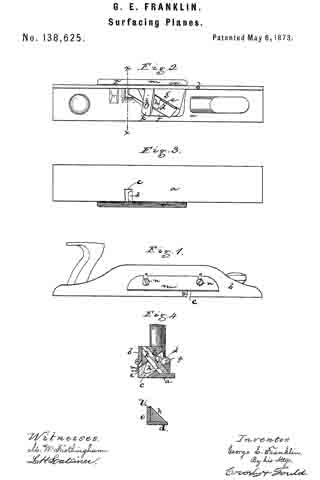
The drawing represents a tool embodying the invention.
Figure 1 is a side view of the plane. Fig. 2 is a top view thereof. Fig. 3 is a bottom view. Fig. 4 is a cross-section on the line x x.
a denotes the bottom plate of the plane; b, an upright, extending from one edge of said plate; c, the throat through which the cutters or plane-bits extend and the chips escape. d e denote the two cutters, set at an angle to both plates a b, and at a right angle to each other, the cutter d resting upon a bed-piece, f, and its cutting-edge extending through the throat c, and so as to be in a horizontal plane just beyond the bottom face of the plate a, and the cutter e sitting edgewise on top of the cutter d, and with its inner face against a bed-piece, g, the cutter e also extending through the throat c, but its cutting-edge being vertical and standing just beyond the outer face of the upright b, the two cutting-edges standing, therefore, at a right angle and being in effect one cutting-edge, bent so as to be one part vertical and one part horizontal. The two cutters are held by an angular clamp, h, which is pressed down against the cutters by a screw, i, passing through a bar, k, and the clamp h has a shoulder, l, extending over the edge of the cutter e, so that not only are the two cutters forced against the bed-faces, but the cutter e is pressed against the cutter d, bringing their cutting-edges together and firmly securing them in position.
On the outer face of the upright b is fastened a gage, m, which, by screws n and slots o is made adjustable, and this gage determines the depth of cut of the two cutters.
As the tool is used, as before described, the edge d cuts across the grain, and the edge e with the grain, and by the action of the two cutters together the work is very rapidly effected, and the block uniformly surfaced or resurfaced.
I claim —
1. The surfacing-plane, formed with two cutters, d and e, having their edges in line and standing one in horizontal and the other in vertical position, combined with the gage m, on the vertical face of the plane, substantially as described.
2. In combination with the two cutters, the clamp h, for holding the cutters, substantially as shown and described.
3. The clamp, formed with the shoulder l, for pressing the cutter e down to the cutter d, substantially as shown and described.
GEO. E. FRANKLIN.
Witnesses:
FRANCIS GOULD,
M. W. FROTHINGHAM.