No. 1,181,004 – Bench Plane (George W. Harvey) (1916)

UNITED STATES PATENT OFFICE.
_________________
GEORGE W. HARVEY, OF JASPER, MISSOURI.
BENCH-PLANE.
_________________
1,181,004. Specification of Letters Patent. Patented Apr. 25, 1916.
Application filed July 22, 1915. Serial No. 41,306.
_________________
To all whom it may concern:
Be it known that I, GEORGE W. HARVEY, citizen of the United States, resident of Jasper, in the county of Jasper and State of Missouri, have made a certain new and useful Invention in Bench-Planes; and I declare the following to be a full, clear, and exact description of the same, such as will enable others skilled in the art to which it appertains to make and use the invention, reference being had to the accompanying drawings, and to letters or figures of reference marked thereon, which form a part of this specification.
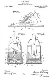
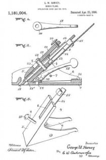
Figure 1 is a side view of the invention. Fig. 2 is a section on the line 2–2, Fig. 3. Fig. 3 is a section on the line 3–3, Fig. 1. Fig. 4 is a section on the line 4–4, Fig. 1. Fig. 5 is a detail perspective view of the bit iron holder. Fig. 6 is a detail top plan view of the adjusting lever.
The invention has relation to bench or carpenters’ planes, and it consists in the novel construction and combination of parts, as hereinafter set forth.
In the accompanying drawings, illustrating the invention, the numeral 2 designates the stock, having side flanges 3, 3, and 4 is the bit iron holder, having an incline 5 and lower side flanges 6, 6, pivoted to the flanges of the stock by a strong cross-pin 7. The bit holder has in its incline a slot 8, open at its upper end, and is provided with a stud 9, projecting upwardly at right-angles to the incline and having a head 10 at its upper end.
Resting upon the bit iron holder incline is the bit iron 11, a cap iron 11′ having therein a slot 12, of keyhole form, adapted to engage the head of the stud, when the bit and cap irons will slide downwardly to position, the contracted portion of the slot engaging the shank of the stud. Projecting from the lower wall of the bit iron, intermediately of its length, is a stud 13, fitting within the slot of the incline. An upwardly projecting, inclined spring arm 14 is secured at its lower end to the lower wall of the incline, and carries intermediately of its length an upwardly projecting squared stud 15, engaging a squared slot or seat 16 of the bit iron.
A wedge 22 has, intermediately of its length, a keyhole slot 23 therein, engaging over the headed end of the stud 9, said wedge having at its upper end a screw 24, having contact with the upper portion of the cap iron, to press said iron, with the bit iron, downwardly against the incline of the bit iron holder and bind it securely in place thereupon.
Located below the spring arm, about midway between the same and the floor of the stock, is a rearwardly projecting inclined lever 18, having at its lower end a pivot upon a vertical pin 19 of the stock, said lever having at its lower end an upper cam surface 20, against which the lower wall of the incline bears, so that when the lever is moved to one side or the other, the cam will engage the bit iron holder and move the same upwardly or allow the same to move downwardly, upon the cross~pin as a pivot, the bit iron holder and bit iron carried thereby rocking upon said cross-pin, to adjust the cutting edge upwardly or downwardly and thereby vary the thickness of the shaving, said lever being easily worked by one finger, without changing the grip upon the handle, so that delicate adjustments, to vary the thickness of the shaving, may be conveniently made. As the bit iron holder and bit iron are adjusted as stated, to vary the thickness of the shaving, a transverse spring 21, located beneath the rear portions of the flanges 6 of the bit iron holder, is put under tension, this transverse spring acting to press the bit iron holder in contact with the cam, and accomplishing the downward recking movement of the bit.
What I claim is:
1. In a plane, a stock, a bit iron holder pivoted to said stock, a bit iron upon said holder, a pressure spring for said holder and said bit iron in rear of said pivot, and a transversely movable adjusting lever having a vertical fulcrum pin connection with said stock and a cam end in contact with said holder forward of said pivot.
2. In a plane, a stock having side flanges, a bit iron holder having side flanges, a bit iron upon said holder, a pivotal cross-pin connecting the flanges of said stock and said holder, a pressure spring for said holder and said bit iron in rear of said cross-pin, and transversely movable adjusting lever having a vertical fulcrum pin connection with said stock and a cam end in contact with said holder forwardly of said cross-pin.
3. In a plane, a stock, a bit iron holder pivoted to said stock, a bit iron upon said holder, a pressure spring for said bit iron and said holder in rear of the pivot thereof, In testimony whereof I affix my signature, and a transversely movable rearwardly projecting lever having at its lower end a vertical fulcrum pin connection with the stock and an upper cam surface bearing against the said holder forwardly of the pivot thereof.
GEORGE W. HARVEY.
Witnesses:
LEIGH I. DODWELL,
ADOLPH McGEE.
Copies of this patent may be obtained for five cents each, by addressing the “Commissioner of Patents, Washington, D. C.”
_________________


