No. 1,102,095 – Plane (John Smith) (1914)

[paiddownloads id=”698″]1102095


UNITED STATES PATENT OFFICE.

_________________

JOHN SMITH, OF POOLER, GEORGIA.

PLANE.

_________________

1,102,095. Specification of Letters Patent. Patented June 30, 1914.
Application filed October 9, 1913. Serial No. 794,225.

_________________

To all whom it may concern:

Be it known that I, JOHN SMITH, a citizen of the United States, and a resident of Pooler, in the county Of Chatham and State of Georgia, have invented a new and Improved Plane, of which the following is a full, clear, and exact description.

This invention relates to woodworking tools and has particular reference to the construction of carpenters’ planes whereby a tool of this character may be adjusted or modified in size and thereby made to serve as a substitute for several different sizes of planes commonly required by a carpenter.

The primary object of the invention, therefore, is to provide a tool of the class indicated which is adapted by the provision of one or more extensions to take the place of a set of planes including a smoothing or block plane, a jack plane, a fore-plane and a jointer.

The foregoing and other objects of the invention will hereinafter be more fully described and claimed and illustrated in the drawings forming a part of this specification in which like characters of reference indicate corresponding parts in all the views, and in which —

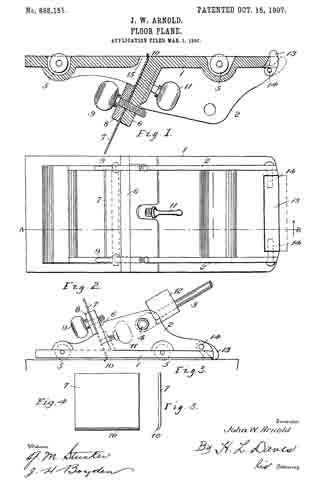
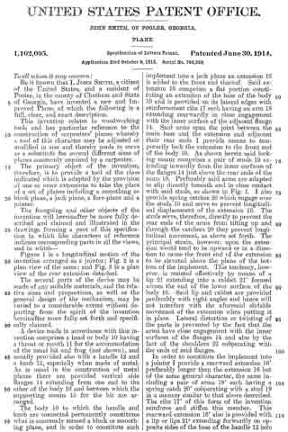
Figure 1 is a longitudinal section invention arranged as a jointer; Fig. 2 is a plan view of the same; and Fig. 3 is view of the rear extension detached.

The several parts of the device may be made of any suitable materials, and the relative sizes and proportions, as well as the general design of the mechanism, may be varied to a considerable extent without departing from the spirit of the invention hereinafter more fully set forth and specifically claimed.

A device made in accordance with this invention comprises a head or body 10 having a throat or mouth 11 for the accommodation of the usual bit and frog (not shown), and nsually provided also with a handle 12 and a knob 13, especially when made of metal. As is usual in the construction of metal planes there are provided vertical side flanges 14 extending from one end to the other of the body 10 and between which the supporting means 15 for the bit are arranged.

The body 10 to which the handle and knob are connected permanently constitutes what is commonly termed a block or smoothing plane, and in order to constitute such of the a plan implement into a jack plane an extension 16 is added to the front end thereof. Said extension 16 comprises a flat portion constituting an extension of the base of the body 10 and is provided on its lateral edges with reinforcement ribs 17 each having an arm 18 extending rearwardly in close engagement with the inner surface of the adjacent flange 14. Said arms span the joint between the main base and the extension and adjacent their rear ends I provide means to temporarily lock the extension to the front end of the body 10. As shown herein said locking means comprises a pair of studs 19 extending inwardly from the inner surfaces of the flanges 14 just above the rear ends of the arms 18. Preferably said arms are adapted to slip directly beneath and in close contact with said studs, as shown in Fig. 1. I also provide spring catches 20 which engage over the studs 19 and serve to prevent longitudinal displacement of the extension 16. The studs serve, therefore, directly to prevent the rear ends of the arms from tilting up and through the catchers 20 they prevent longitudinal movement, as above set forth. The principal strain, however, upon the extension would tend to be upward or in a direction to cause the front end of the extension to be elevated above the plane of the bottom of the implement. This tendency, however, is resisted effectively by means of a lip 21 extending into a rabbet 21′ formed across the end of the lower surface of the body 10. Said lip and rabbet are provided preferably with right angles and hence will not interfere with the aforesaid slidable movement of the extension when putting it in place. Lateral distortion or twisting of the parts is prevented by the fact that the arms have close engagement with the inner surfaces of the flanges 14 and also by the fact of the shoulders 22 cooperating with the ends of said flanges.

In order to constitute the implement into a jointer I provide a rearward extension 16′ preferably longer than the extension 16 but of the same general character, the same including a pair of arms 18′ each having a spring catch 20′ cooperating with a stud 19 in a manner similar to that above described. The ribs 17′ of this form of the invention reinforce and stiffen this member. This rearward extension 16′ also is provided with a lip or lips 21a extending forwardly on opposite sides of the base of the handle 12 into cooperation with the rabbet 21′, as shown in Fig. 1. The base of this extension is provided with a socket or notch 16a into which the base of the handle is snugly seated when the extension is shoved forwardly into place. Either of these extensions may be almost instantly attached or detached. The manner of detachment may consist in the holding of the body 10 in one hand and with the other hand spanning the handle or knob and causing two of the fingers of such hand to lift upon the free ends 20a of the catches. Such handle or knob constitutes therefore a fulcrum to assist in such lifting movement, and the pressure between the hand and the ends of the fingers causes sufficient outward or rearward movement of the extension to unlock the catches from the studs. The two parts, then, may be pulled apart directly without resistance. The assembling movement will be readily understood from what has been said above, and requires but a simple shove of the extension directly into its place, the ends 20a of the catches causing the catches to ride automatically over and into engagement with the studs.

Having thus described my invention, I claim as new and desire to secure by Letters Patent:–

1. In an implement of the class set forth the combination of a main plane body having a base and upwardly extending side flanges, an extension for said body comprising a base adapted to aline with the body base, said extension also including a pair of arms extending along the body base adjacent the inner surfaces of said flanges, a pair of studs secured to said iianges and extending toward each other in contact with the upper surfaces of said arms to prevent downward tilting of the extension, and means engaging over said studs to prevent longitudinal displacement of the extension.

2. In a plane, the combination with a main body including a base and a pair of upwardly extending lateral flanges, of an extension for either end of said base, said extension comprising a base adapted to aline with the aforesaid base and also including a pair of arms extending along the top of the main base just within the flanges thereof, a pair of studs cooperating directly with the upper surfaces of said arms, a pair of spring catches secured to the arms and adapted to snap automatically over said studs when the extension is shoved into place, and means cooperating with said arms to prevent the upward tilting of the extension.

3. In a plane, the combination of a main body including a base, vertical side flanges extending upwardly from the base, and a pair of studs extending inwardly from the inner faces of said side flanges in alinement with each other and spaced above the upper surface of said base, an extension for the main body including a base adapted to abut against the aforesaid body base, a pair of rigid arms extending from the extension and lying snugly between said studs and the main body base, and means on the arms cooperating with said arms and studs serving to prevent accidental removal of the extension from the base.

In testimony whereof I have signed my name to this specification in the presence of two subscribing witnesses.

JOHN SMITH.

Witnesses:
JOHN B. SMITH,
E. CARMEL MURPHY.

_________________

Copies of this patent may be obtained for five cents each, by addressing the “Commissioner of Patents, Washington, D. C.”
_________________

No. 868,151 – Floor-Plane (John Walter Arnold) (1907)

[paiddownloads id=”647″]868151


UNITED STATES PATENT OFFICE.

_________________

JOHN WALTER ARNOLD, OF ATLANTA, GEORGIA.

FLOOR-PLANE.

_________________

868,151. Specification of Letters Patent. Patented Oct. 15, 1907.
Application filed March 1, 1907. Serial No. 359,966.

_________________

To all whom it may concern:

Be it known that I, JOHN WALTER ARNOLD, a citizen of the United States, residing at Atlanta, in the county of Fulton and State of Georgia, have invented certain new and useful Improvements in Floor-Planes, oi which the following is a specification.

This invention pertains to floor scrapers, more particularly of the roller carriage type, and has as its object to provide a device of that character whereby the same may be easily and noiselessly moved about a floor and remove therefrom any roughness or unevenness and leave the same in one smooth even plane.

Another object is that of providing the scraper with a means for automatically tilting the same on every backward movement thereof and thereby to raise the scraper blade hom scratching the planed surface of the floor. lts further object provides for means whereloy the scraper may be regulated to scrape heavily or lightly without requiring any physical exertion on the part of the operator.

With these and other objects of importance in view the invention consists in the construction and combination of parts hereinafter more fully described and pointed out in the claims.

ln the accompanying drawings, forming a part of this specification: Figure 1 is a. longitudinal section. Fig. 2 is a top plan view thereof. Fig. 3 is a side elevation reduced, and Figs. 4 and 5 show the blade in detail.

Similar reference numerals designate corresponding parts in the different figures.

The device comprises a truck of any suitable design mounted upon rollers 5 and having a. base plate 1, and its vertical side walls 2 adapted to receive an operating handle 3 which is journaled thereon by a bolt 4. Said base plate 1 is bifurcated at its rear end as seen in Fig. 2, said bifurcations being adapted to receive therebetween the cam foot 13.

Numeral 6 designates an upright which with the clamping plate 8 and thumb screws 9 constitute the supporting means for the scraper blade 7 which is forwardly inclined as against the usual types which are inclined rearwardly or towards the operating handle. The scraper-blade 7 thus inclined sets its active edge 10 to a drag or relieved position by which all possibilities of its jamming against knots or tearing splinters is obviated. This position rather tends to permit of its readily passing over such obstructions and yet remove therefrom any roughness. The edge 10 of the blade is turned slightly forward, or in the direction of the movement of the scraper, and by means of the regulating screw 11 it may be set to cut at various depths. The opening 15 in the base of the scraper being sufficiently wide to permit this.

To vary the amount of pressure necessary to exert upon the planer as is required on floors of different grains and in the different stages of cleaning a floor, the truck 1, is weighted by one or more weights 12 which are threaded upon the handle.

ln cleaning a floor it is desirable that the scraper-blade should pass over the same only in the necessary operative movements, as any more than that has a dulling and scratching effect on the finish. To remedy this defect my device is provided with a lifting foot or cam 13 suitably journaled to the rear end oi the planer as at 14. Said foot may be operated by gravity, or a spring may be provided to facilitate its movement. In the forward movement of the scraper the cam 13 will remain inactive, that is, — following behind the planer; but upon the reverse movement of the planer the cam immediately engages against the floor and turning upon its bearings 14, raises the rear end of the truck which elevates the edge 10 of the blade 7 sufficiently to permit of its clearing the floor. This operation likewise saves undue wearing on the edge 10 of the blade.

What is claimed as new is:–

1. A floor scraper comprising a truck having a base-plate bifurcated at its rear end, a cam foot pivoted at said end between the bifurcations, a forwardly inclined scraper-blade support located intermediate the ends of the base-plate, a scraper-blade and means for adjustably connecting the same to said support, a roller journaled in rear of the blade, and forward of the cam-foot, another roller journaled in front of the blade, and an operating handle connected to the truck.

2. In a floor scraper the combination of a carriage, an operating handle journaled thereto, removable weights threaded upon said handle, an integral and forwardly inclined upright having a scraper blade secured thereto, the cutting edge of said blade being turned outwardly, means for vertically adjusting said blade, and separate means for adjusting the cutting depth of said outwardly turned edge, and a cam foot journaled to the rear end of the carriage and projecting beyond said carriage, said cam foot adapted to tilt the carriage during its inoperative movement.

In testimony whereof I affix my signature in presence of two witnesses.

JOHN W. ARNOLD.

Witnesses:
W. J. NALLEY,
I. L. HAMMOND.

No. 439,061 – Bench-Plane (Jerome E. Greene) (1890)

[paiddownloads id=”467″]439061


UNITED STATES PATENT OFFICE.

_________________

JEROME E. GREENE, OF TOCCOA, GEORGIA, ASSIGNOR
OF ONE-THIRD TO JOHN McJUNKIN, OF SAME PLACE.

BENCH-PLANE.

_________________

SPECIFICATION forming part of Letters Patent No. 439,061, dated October 21, 1890.
Application filed November 30, 1889. Serial No. 332,142. (No model.)

_________________

To all whom it may concern:

Be it known that I, JEROME E. GREENE, a resident of Toccoa, in the county of Habersham and State of Georgia, have invented certain new and useful Improvements in Roller Bench-Planes; and I do hereby declare the following to be a full, clear, and exact description of the invention, such as will enable others skilled in the art to which it pertains to make and use the same.

The object of my invention is to improve the efficiency of bench-planes and to provide simple and durable devices for adjusting and holding the bit, that can be quickly and conveniently operated; and it consists in the matters hereinafter described and pointed out.

In the accompanying drawings, Figure 1 is a vertical longitudinal section on line a b. Fig. 2 is a side elevation of a roller, and Fig. 3 is a perspective view of a detail. Fig. 4 is a side elevation of a corrugated roller. Fig. 5 is a partial section on line c d of Fig. 1, and Fig. 6 is a partial longitudinal section near one side of the plane.

The body of the plane is preferably made of metal having the side and bottom cast in one piece.

A cross-piece 1, situated just behind the location for the bit, may be cast with the other parts, and also two wedge-shaped pieces 2, one on each side. A handle, which may be secured to the body in any convenient manner, is denoted by 3.
In the present instance the handle is provided in its lower end with an undercut recess, which engages a suitable lug on the plane-body and is then fastened in such position by a screw, as indicated in Fig. 1. A bit is indicated by 4. It is placed on the inclined front side of the support 1 and beneath the side parts 2. The latter at their lower extremities are reduced to a thin edge and receive above them a cap or plate 5, which is conveniently secured to the parts 2 by screws. The part 1 strengthens the plane-body. It also supports the bit at its lower part in a horizontal direction, the slipping of the bit in an approximately vertical direction being prevented by a locking or clamping device which forces the bit against suitable bearings. The spring 5 is made sufficiently strong to force the lower end of the bit upon said support 1.

The bit is locked in any desired position by means of an eccentric 6, journaled in any suitable manner, as by securing-bones 7, having bearings for a rod, bar, or pin 8 to the sides of the plane-body. These bearings are open on the side toward the bit, as indicated in in Fig. 1, and permit the rod 8 with the cam to be inserted or removed when desired by suitably turning them and taking out the bit, if necessary. A handle 9 affords means for suitably moving the eccentric, the bit being released by raising the handle, and gripped or locked by lowering it.

The cap 5 can be made of spring metal, and being prolonged beyond the bearings 2 and bent down upon the bit, as shown, will produce a spring-pressure upon the same. To relieve this tension, the spring-plate is released by loosening its retaining-screws.

As illustrated in Fig. 1, the cap is in close contact with its supports 2 throughout the entire length of the latter. It is obvious that if the cap is of suitable curved form and the compression applied by means of the screws is just sumcient to bend it down upon supports 2 they will appear as represented in Fig. 1.

In Fig. 6 an enlarged view is shown, indicating a small space between the cap and support, which could not be well indicated in Fig. 1. The cap at its lower end has a knife-edge, it being essential that it have a closely-fitted bearing on the bit. By the described construction the fastening together of a bit and its cap in manner heretofore practiced is avoided and the bit can be independently removed or inserted in the plane, and the adjustment of the bit to the cap requires no special attention, for the reason that the cap is permanently fixed in its proper position and the proper adjustment of the bit with reference to the bottom of the plane necessarily secures a suitable adjustment with respect to the cap.

In front of the bit is arranged a roller 10, which is preferably corrugated and is provided with circumferential shoulders 11, forming recesses adapting it to receive springs and be supported thereby. These springs are secured to the body of the plane — one near each side — in any convenient manner, as by screws 13, and a block or saddle 14, having bearings 15, rests upon the reduced ends of the roller immediately above the springs, and the roller is thus sustained between the springs and the bearing-blocks. It can be adjusted vertically to the extent of the resiliency of the springs by means of the screw 16, working through a cross-bar 17 secured in the side of the plane. By running the screw 16 up or down the vertical position of the roller is varied and also its distance from the bit. The bit can in this manner be set according to the nature of the wood or material upon which it is used and the kind of work to be done.

I am aware that rollers have been used in connection with plane-bits, and also devices for adjusting the bit and clamping it from the rear side thereof, and I do not broadly claim such features. I have, however, simplified prior constructions and added to the efficiency of the tool. It will be noted that parts 1 and 2 are cast solid with the body of the plane, and that the spring-plate bears upon the bit at both ends against the action of a simple cam, which latter is so arranged and supported that it is held in its bearings by the bit and can readily be inserted or removed by removing said bit. The structure is quite simple and the parts easily assembled and regulated, and the bit is held very securely. The roller, supported on horizontal springs in or very close to the lower face of the plane, is adapted to bear on the object being planed. The grooves or recesses forming shoulders at the ends of the rollers receive these springs, which lie in a horizontal direction just above the bottom of the plane. The bearing-block 14 rests in the same recesses and embraces the reduced ends of the roller in manner to prevent lateral displacement holding the roller adjustable against the action of the springs.

Having thus described my invention, what I desire to secure by Letters Patent is —

1. In a bench-plane, the combination of the transverse part 1, having a rearwardly-inclined front, the wedge-shaped side parts 2, said parts 1 and 2 being cast solid with the body of the plane, with the bit and the eccentric having journals supported in boxes 7, fixed to the sides of the plane, adapted to press the bit against the bottom of the side pieces, substantially as set forth.

2. In a bench-plane, the combination ofthe transverse part 1, having the inclined front, the wedge-shaped side pieces 2, the bit, the cap fixed upon said side pieces and pressing upon the bit at both its ends, and the eccentric having journals supported in boxes 7, fixed to the sides of the plane, with a handle adapted to press the bit against the bottom of the side pieces and against the cap, substantially as set forth.

3. In a bench-plane, the combination of the bit with a roller, springs secured in the bottom of the plane for supporting the said roller near the edge of the bit, and means for pressing the roller upon its spring-supports, substantially as set forth.

4. In a bench-plane, the combination of the bit, the recessed roller, springs extending into the recesses to support the roller, bearing-blocks resting in said recesses upon the upper side of said roller, and an adjusting-screw for varying the pressure of the bearing-blocks upon the roller, substantially as set forth.

In testimony whereof I have signed this specification in the presence of two subscribing witnesses.

JEROME E. GREENE.

Witnesses:
JOHN McJUNKIN,
E. P. SIMPSON.

No. 180,867 – Improvement In Bench-Planes (Jackson Gorham) (1876)

[paiddownloads id=”266″]180867


UNITED STATES PATENT OFFICE.

_________________

JACKSON GORHAM, OF CRAWFORDVILLE, GEORGIA, ASSIGNOR TO HIMSELF AND CHARLES E. SMITH, OF SAME PLACE.

IMPROVEMENT IN BENCH-PLANES.

_________________

Specification forming part of Letters Patent No. 180,867, dated August 8, 1876; application filed July 11, 1876.

_________________

To all whom it may concern:

Be it known that I, JACKSON GORHAM, of Crawfordville, in the county of Taliaferro and State of Georgia, have invented an Improvement in Bench-Planes, of which the following is a specification:

My invention consists of a stud applied on the top of a smoothing-plane stock near the heel, and adapted to fit between the thumb and forefinger of the right hand, while the palm bears against the heel of the stock, whereby the pressure of the hand is distributed over a larger surface, and is thus diminished on the small area heretofore employed for driving the plane by pressing against the heel of the stock. It also affords a bearing or rest for a part of the hand not heretofore having any support on the stock, and therefore making the work easier.

The drawing is a perspective side elevation of a plane-stock constructed according to my invention.

A is the stock, and B the stud, which I apply as above described. The rear side of the stud a is made in suitable transverse convex; form and vertical concave form, to make an easy bearing for the hand. The handle may be made separate from the stock and attached to it, or it may be worked out of the block in connection with it.

Having thus described my invention, what I claim as new, and desire to secure by Letters Patent, is —

The plane-stock A, having the stud B, constructed in the form represented at a, and located relatively to the heel of the stock, substantially as specified.

JACKSON GORHAM.

Witnesses:
V. T. SMITH,
CHARLES A. BEAZLEY.

No. 23,678 – Bench Plane Stock (Jackson Gorham) (1859)

[paiddownloads id=”80″]23678


UNITED STATES PATENT OFFICE.

_________________

JACKSON GORHAM, OF BAIRDSTOWN, GEORGIA.

BENCH-PLANE STOCK.

_________________

Specification of Letters Patent No. 23,678, dated April 19, 1859.

_________________

To all whom it may concern:

Be it known that I, JACKSON GORHAM, of Bairdstown, in the county of Oglethorpe and State of Georgia, have invented a new and useful Improvement in Joiners’ Planes; and I do hereby declare that the following is a full, clear, and exact description of the same, reference being had to the annexed drawings, making a part of this specification, in which —

Figure 1, is a longitudinal vertical section of my invention taken in the line x, x, Fig. 2. Fig. 2, is a plan or top view of ditto.

Similar letters of reference indicate corresponding parts in the two figures.

This invention consists in having the stock of the plane formed of wood with metal sides and the front part of the wooden portion made adjustable by means of set screws, so that the “throat” may be enlarged and contracted at pleasure, as the nature of the work may require.

The invention is designed to facilitate the construction of planes and render them more perfect than those of ordinary construction.

To enable those skilled in the art to fully understand and construct my invention I will proceed to describe it.

A, represents the plane stock, which is formed of a wooden center a, a’, with a metal strip or plate b, at each side. The back part a’, of the wooden part of the stock is permanently attached to the metal plates b, b, but the front part a, is adjustable, that is to say, it is allowed to slide longitudinally between the plates b, b, and nearer to or farther from the part a’, of the central wooden portion as may be desired, — the part being secured at any desired point by set screws ax, ax.

The throat c, of the plane is formed between the parts a, a’, of the central wooden portion of the plane, the front end of the part a’, being inclined, as shown at d, and the back end of the part a, having a double inclined surface, as shown at e, f. This form of the adjoining ends of the parts a, a’, constitute the throat, and as the part a, is adjustable the throat it may be seen may be enlarged or contracted as desired.

The lower edges of the metal slides b, b, do not quite extend down to the bottom of the wooden portion a, a’, of the stock, and consequently the bottoms of the wooden portion a, a’, constitute the “sole” of the plane. The iron B, is of usual form and is fitted against the end d, of the part a’, and secured thereto by a wooden key or wedge g, which is driven behind flanches h, h, formed on the inner sides of the plates b, b, — the flanches being cast with the plates b, b.

From the above description it will be seen that the plane may be very readily constructed, much more so, than if made entirely of wood in the ordinary way. The throat c, is formed or made without difficulty and its orifice at the cutting edge of the iron B, may be contracted or enlarged as occasion may require. The plates b, b, may be of cast metal, and the central part a, a, may be of beech or other similar wood.

Having thus described my invention what I claim as new and desire to secure by Letters Patent, is,

Constructing the plane stock of a central wooden portion a, a’, secured between metal side plates b, b, provided with flanches h, h, the part a’, being permanently secured between the plates b, b, and the part a, rendered adjustable between said plates by set screws ax, ax, substantially as and for the purpose set forth.

JACKSON GORHAM.

Witnesses:
GEO.W. NEAL,
WM. O. CHENEY, Jun.