No. 794,667 – Plane (Gustav Dechant) (1905)

[paiddownloads id=”623″]794667


UNITED STATES PATENT OFFICE.

_________________

GUSTAV DECHANT, OF KIEL, GERMANY.

PLANE.

_________________

SPECIFICATION forming part of Letters Patent No. 794,667, dated July 11, 1905.
Application filed May 10, 1904. Serial No. 207,307.

_________________

To all whom it may concern:

Be it known that I, GUSTAV DECHANT, a subject of the German Emperor, and a resident of Gerhardtstrasse 5, Kiel, Germany, have invented certain new and useful Improvements in Planes, of which the following is a specification.

My invention relates to improvements in planes holding several adjustable blades or bits; and its object is to provide a plane which may be used successively for different kinds of work, such as chipping, planing, finishing, rabbeting, &c., thus uniting several tools in one.

I attain my object by the construction illustrated herewith on the accompanying drawings, in which —

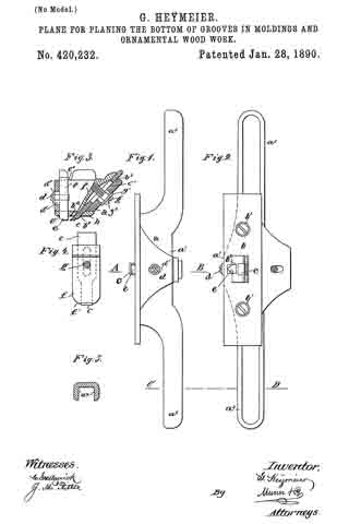
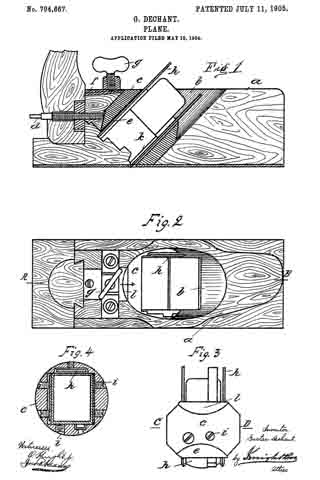
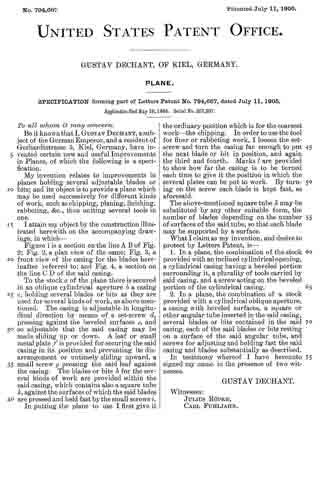
Figure 1 is a section on the line A B of Fig. 2; Fig. 2, a plan view of the same; Fig. 3, a front view of the casing for the blades hereinafter referred to; and Fig. 4, a section on the line C D of the said casing.

To the stock a of the plane there is secured in an oblique cylindrical aperture b a casing c, holding several blades or bits as they are used for several kinds of work, as above mentioned. The casing is adjustable in longitudinal direction by means of a set-screw d, pressing against the beveled surfaces e, and so adjustable that the said casing may be made sliding up or down. A leaf or small metal plate f is provided for securing the said casing in its position and preventing its disarrangement or untimely sliding upward, a small screw g pressing the said leaf against the casing. The blades or bits h, for the several kinds of work are provided within the said casing, which contains also a square tube k, against the surfaces of which the said blades are pressed and held fast by the small screws i.

In putting the plane to use I first give it the ordinary position which is for the coarsest work — the chipping. In order to use the tool for fmer or rabbeting work, I loosen the set-screw and turn the casing far enough to put the next blade or bit in position, and again the third and fourth. Marks l are provided to show how far the casing is to be turned each time to give it the position in which the several plates can be put to work. By turning on the screw each blade is kept fast, as aforesaid.

The above-mentioned square tube k may be substituted by any other suitable form, the number of blades depending on the number of surfaces of the said tube, so that each blade may be supported by a surface.

What I claim as my invention, and desire to protect by Letters Patent, is —

1. In a plane, the combination of the stock provided with an inclined cylindrical opening, a cylindrical casing having a beveled portion surrounding it, a plurality of tools carried by said casing, and a screw acting on the beveled portion of the cylindrical casing.

2. In a plane, the combination of a stock provided with a cylindrical oblique aperture, a casing with beveled surfaces, a square or other angular tube inserted in the said casing, several blades or bits contained in the said casing, each of the said blades or bits resting on a surface of the said angular tube, and screws for adjusting and holding fast the said casing and blades substantially as described.

In testimony whereof I have hereunto signed my name in the presence of two witnesses.

GUSTAV DECHANT.

Witnesses:
JULIUS RõPKE,
CARL FUHLJAHN.

No. 547,924 – Instrument For Planing Or Scraping Out Round Objects (Peter Keltsch And Paul Keltsch) (1895)

[paiddownloads id=”519″]547924


UNITED STATES PATENT OFFICE.

_________________

PETER KELTSCH AND PAUL KELTSCH, OF ERLANGEN, GERMANY.

INSTRUMENT FOR PLANING OR SCRAPING OUT ROUND OBJECTS.

_________________

SPECIFICATION forming part of Letters Patent No. 547,924, dated October 15, 1895.
Application filed February 12, 1895. Serial No. 538,080. (No model.)

_________________

To all whom it may concern:

Be it known that we, PETER KELTSCH and PAUL KELTSCH, subjects of the King of Bavaria, and residents of Erlangen, in the Kingdom of Bavaria, German Empire, have invented new and useful improvements in instruments adapted for planing or scraping out round objects, as well as for hollowing out or grooving square or rectilinear objects, of which the following is a specification.

This invention relates to an instrument adapted for planing or scraping out round objects, as well as for hollowing out or grooving square or rectilinear objects.

The instrument is particularly adapted for the construction of carriage-poles, shafts, and telegraph and hop poles.

The invention is illustrated in the accompanying drawings, wherein —

Figure 1 shows the instrument as used for grooving or hollowing out flat objects. Figs. 2 and 3 are transverse sections taken, respectively, on the lines x x and y y of Fig. 1, and Fig. 4 is a part side view of Fig. 1. Fig. 5 shows the instrument as used for round carving, and Fig. 6 is a part side view of same. Fig. 7 is a perspective view of part of the instrument shown in Fig. 5, and Figs. 8 and 9 are representations showing the method of working the instrument when carving cylindrical or prismatic shaped woods.

The instrument consists of a knife a, which possesses a bow-shaped cutting-edge, the knife itself being strengthened at the back by curving it centrally. This bow shape of the knife a can either be concave, as in Fig. 1, for hollowing out flat surfaces, or can be convex, as in Fig. 5, for carving round-shaped surfaces. On the inner side of the back is screwed a disk-shaped block b, which is likewise constructed as a knife, and has a fork-shaped slit d at each end and is secured in its place on the knife a by means of screws e. The gage-plate b stands on the cutting-plate a, as shown in Figs. 2, 3, and 5. The plate b acts as a gage to limit the depth of the cut, and, is made removable to facilitate the grinding of the blade.

When it is desired to hollow out flat objects, the instrument shown in Fig. 1 must be used, and to carve round objects the instrument shown in Fig. 5 must be used.

Having fully described our invention, what we claim as new, and desire to secure by Letters Patent, is —

An instrument for carving round or hollowing out flat objects, consisting of a bow-shaped knife, an obliquely rising cutting rest having a concaved top surface, and provided with slots in the base flange whereby the rest is adjusted on the knife, as and for the purpose specified.

In witness whereof we hereunto set our hands in presence of two witnesses.

PETER KELTSCH.
PAUL KELTSCH.

Witnesses:
KONRAD MILLING,
FLANDER BEYER.

No. 420,232 – Plane For Planing The Bottom Of Grooves In Moldings And Ornamental Wood-Work (Gustav Heÿmeier) (1890)

[paiddownloads id=”458″]420232


UNITED STATES PATENT OFFICE.

_________________

GUSTAV HEŸMEIER, OF BREMEN, GERMANY.

PLANE FOR PLANING THE BOTTOMS OF GROOVES
IN MOLDINGS AND ORNAMENTAL WOOD-WORK.

_________________

SPECIFICATION forming part of Letters Patent No. 420,232, dated January 28, 1890.
Application filed June 1, 1889. Serial No. 312,910. (No model.)

_________________

To all whom it may concern:

Be it known that I, GUSTAV HEŸMEIER, sculptor, of Bremen, in the Free State of Bremen and German Empire, have invented a new and useful Improvement in Planes for Planing the Bottoms of Grooves in Moldings and Ornamental Wood-Work, of which the following is a specification, reference being had therein to the accompanying drawings.

My invention relates to tools for planing the bottoms of grooves in moldings and ornamental wood-work, and has for its object to provide an effective tool for that purpose.

The invention consists in a plane of the character specified, constructed as hereinafter described and claimed.

Reference is to be had to the accompanying drawings, forming a part of this speciiication, in which similar letters of reference indicate corresponding parts in all the figures.

Figure 1 is a front view of the invention. Fig. 2 is a bottom view. Fig. 3 is a cross-section on the line A B of Fig. 1. Fig. 4 is a view of the blade with its guard-plate, and Fig. 5 is a cross-section of one of the handles of the tool on the line C D of Figs. 1 and 2.

The invention consists of a frame a, preferably hollow, as shown, and made of metal, and constituting the central portion a’ and the handles a2. On the bottom of the frame a is centrally located a plate b, secured by screws b’ to the central portion a’ of frame a. The plate b is provided with an opening b2, through which projects a blade c extending up through an opening b3 in the top of frame a, the blade c being movable through the openings b2 and b3. The blade c is clamped in fixed position by means of a shield-plate f also projecting through openings b2 and b3, and a screw g, passing through a washer g’, a slot g2 in frame a, over which the washer g’ extends, and a slot c’ in blade c, and engages plate f. By means of this construction the plate f and blade c may be adjustably raised and lowered and clamped in position. Within the central portion a’ is also located a vertical guide-piece e, projecting through an opening e’ in the plate b and opening e2 in the top of frame a, and vertically adjustable by means of a screw d engaging the guide-piece e and extending through a slot d’ in frame a, and a washer d2 overlapping the slot d’. The lower end of piece e projects in front of the projecting end of blade c, is in the form of a tooth, and is made of bone or other suitable material.

The piece e prevents the blade c from cutting too deeply into the wood.

The depth of the cavity to be planed is determined by the length of the blade c projected beyond the plate b.

The lower end of the plate f is formed with the rounded edge f’, and when the bottom of a groove is to be planed the plate f is adjustably lowered so as to bring its lower end down to the cutting-edge of the blade c, and the shape of the curved bottom of the groove is thereby retained while the tool is planing the bottom of the groove.

Having thus fully described my invention, l claim as new and desire to secure by Letters Patent —

A tool for planing moldings, consisting of the frame a, with handles a2, the removable plate b, with openings b2 e’, the vertically-adjustable curved shield-plate f, and the vertically-adjustable slotted blade c, projecting through opening b2, the binding-screw g, extending through slotted blade c and engaging plate f and the vertically-adjustable tooth e, projecting in front of the edge of blade c, and having the adjusting-screw d extending through the slot d’ in frame a, and the overlapping washer d2, substantially as shown and described.

In witness whereof I have hereunto set my hand in presence of two witnesses.

GUSTAV HEŸMEIER.

Witnesses :
EARNST BIERNRITH,
HUGO MÜHLENBACH.

No. 415,918 – Plane (Wilhelm Meister) (1889)

[paiddownloads id=”456″]415918


UNITED STATES PATENT OFFICE.

_________________

WILHELM MEISTER, OF APOLDA, SAXE-WEIMAR-EISENACH, GERMANY.

PLANE.

_________________

SPECIFICATION forming part of Letters Patent No. 415,918, dated November 26, 1889.
Application filed May 28, 1889. Serial No. 312,470. (No model.)

_________________

To all whom it may concern:

Be it known that I, WILHELM MIEISTER, manufacturer, of Apolda, in the Grand Duchy of Sane-Weimar-Eisenach and German Empire, have invented new and useful Improvements in Planes, of which the following is a specification, reference being had therein to the accompanying drawings.

This invention relates to carpenters’ planes, and has for its object to provide a carpenter’s plane which will be strong and durable, and in which the bit will be effectively held from slipping.

The invention consists in a carpenter’s plane constructed as hereinafter described and claimed.

Figure 1 is a side view, in elevation, of a plane constructed in accordance with this invention. Fig. 2 is a longitudinal section; and Fig. 3 is a transverse section on the line A A, Fig. 2.

Heretofore in the ordinary construction of carpenters’ planes with an opening extending through the stock from top to bottom and an adjustable bit or planing-iron located in the opening it has been found that the stock is considerably weakened and is liable to be broken, owing to the opening extending through the stock from top to bottom. Moreover, the bit in such construction is apt to slip. To obviate these objections, I have devised the following construction: d indicates the stock of a carpenter’s plane formed, instead of the old form of opening extending through the stock from top to bottom, with an opening e, extending through the bottom and sides of the stock, the opening in the sides being of such size as to permit the shavings to pass out laterally from the stock. The opening e, as shown, extends only part way toward the top of the stock. Within the opening e is located the bed-plate b, secured by screws c, and upon the bed-plate b is located the bit or planing-iron a, held by the clamping-plate f and the screws g, engaging the bed-plate b. The heads of the screws g are formed with cross-slots or holes g’,with which a tool inserted laterally into the opening e may be engaged. The bit a, is formed with a slot a’ open at its rear end, so that the bit may be slid, by means of the slot a’, into engagement with and removed from the screws g. By loosening the screws g with a tool inserted laterally into the opening e the bit a may be adjusted and then secured by tightening the screws g.

By means of this invention a strong stock is provided, the bit maybe quickly and readily adjusted, and will be held from slipping.

Having thus described my invention, what I claim as new, and desire to secure by Letters Patent, is —

l. A carpenter’s plane having a stock with an opening for the bit extending part way toward the top of the stock and through its sides for the escape of shavings, a bit with a slot open at the rear end of the bit, and a bed-plate, clamping-plate, and screws, substantially as shown and described.

2. A carpenter’s plane having a stock with an opening for the bit extending part way toward the top of the stock and through its sides for the escape of shavings, a bit, bed-plate, clamping-plate, and screws, the screws having heads with cross-slots, substantially as shown and described.

In witness whereof I have hereunto set my hand in presence of two witnesses.

WILHELM MEISTER.

Witnesses:
RICHARD MEISTER,
JULIUS MEISEL.

No. 198,180 – Improvement In Bench-Planes (Heinrich Baecker) (1877)

[paiddownloads id=”287″]198180


UNITED STATES PATENT OFFICE.

_________________

HEINRICH BAECKER, OF REMSCHEID, GERMANY.

IMPROVEMENT IN BENCH-PLANES.

_________________

Specification forming part of Letters Patent No. 198,180, dated December 18, 1877.; application filed October 8, 1877.

_________________

To all whom it may concern:

Be it known that I, HEINRICH BAECKER, of Remscheid, Germany, have invented Improvements in the Construction of Planes, of which the following is a specification:

This invention relates to bench-planes, the common form of which consists of a stock in which the plane-iron is fastened by means of wedges. These plane-irons are, in their main part, composed of an iron plate, to the end of which a strip or facing of steel is attached to form the cutting-edge. Such planes are deficient in many respects. They are rendered expensive by the forging operation necessary to unite the main part of the plane-iron and its steel facing, which mode of manufacture often ruins the structure. The mode of their production frequently renders the said irons defective by destroying the high quality required for the steel cutting-edge. Such irons require to be bulky, and therefore more difficult to grind, and on account of the limited extent of their steel portion must soon be destroyed when frequently ground.

My invention relates to that class of planes wherein the iron or bit is composed of a plate having an even thickness, and composed entirely of steel — such an iron or bit as may be sharpened until its length is so diminished that it can no longer be supported in the stock.

My invention consists in the means for securing and adjusting such an iron or bit in the plane-stock, the details of which are too fully hereinafter set forth to need preliminary description.

In the accompanying drawings, illustrating my invention, in which like reference-characters indicate the same parts, Figure 1 is a plan view, and Fig. 2 an edge view, of the plane iron or bit; Fig. 3 is a plan view, and Fig. 4 an edge view, of the upper break-iron. Fig. 5 is a plan view, and Fig. 6 an edge view, of the under break-iron, with the adjusting mechanisms attached; Fig. 7, a view of the clamping mechanism. Fig. 8 shows the clamping-screw, and Fig. 9 an operating-key. Fig. 10 shows an adjusting-screw. Fig. 11 is a vertical section of all the parts fitted together in operative position. Fig. 12 is a plan view, and Fig. 13 an edge view, of a rabbet-plane iron, and Fig. 14 is a modification of the mode of fastening the iron or bit in place.

The steel iron or bit 5 is composed of a thin sheet of steel, of even thickness, which is sharpened at its bottom edge, and it is provided with a slot, 2, extending centrally from its top edge to a distance beyond its middle part. It is adjusted in the plane-stock between two break-irons, 8 9, one of which (the lower, 9) is secured to the plane-stock. The iron or bit lies between these break-irons, as in Fig. 11, and the said devices are fastened securely together by means of a clamping-screw, 10, whose stem passes through a hole, 11, in the under break-iron 9, through the slot 2 in the iron or bit, and enters a screw-threaded hole, 12, tapped into the upper break-iron 8. When the iron or bit is properly adjusted between these break-irons, it may be firmly secured by properly tightening said clamping-screw. The upper break-iron 8 and the plane iron or bit are prevented from moving laterally with respect to the under break-iron 9 by means of a pin, 13, projecting from the inner face of the under break-iron 9, passing through the slot 2 of the iron or bit, and entering a hole, 14, in the upper break-iron 8. The parts thus held together are secured in the mortise in the plane-stock 15 by means of an arm, 16, projecting rearward from the under break-iron, and fastened to the stock 15 by means of a screw. The lower end of the under break-iron rests upon one side of the mortise, where it is secured by screws 40, while the front surface of the end of the upper break-iron rests upon the other side of said mortise, the devices being thus held steadily in place.

In order that the iron or bit 5 may be adjusted while its break-irons are hired in the mortise in the plane-stock, the head 6 of the clamping-screw is provided with gear-teeth, fitting a worm, 4, the shank 7 of which turns in arms 17 18 projecting from the rear face of the under break-iron 9. The shank 7 of this worm is provided with a squared head, 19, which fits a similar socket in a turning-key, 20.

By these devices the said clamping-screw 10 may be turned in and out of the screw-threaded hole 12 by inserting the key 20 through a hole (not shown) in the side of the plane-stock, engaging the same with the head 19 and operating said key in the proper direction.

In order to adjust the plane-iron vertically with respect to the break-irons and plane-stock, and thus protrude its cutting-edge the desired distance, each of the break -irons is provided with slots in which a pin connected with said plane-iron may freely play. The slot in the upper break-iron is marked 21, and that in the lower break-iron is marked 22. The pin 23, operating the iron 5, projects from a hub, 24, and enters one of two holes, 25 26, with which said plane-iron is provided. An ad-
justing-screw, 27 , having a screw-threaded shank, which runs in a threaded hole tapped through the hub 24, is supported in a collar, 30, fast to the underbreak-iron, and its squared head (adapted to fit the socket of the turning-key 20) projects above the plane-stock. This construction permits the rotation of said screw 27 to raise or lower the hub 24, and to impart a like movement to the plane-iron without disturbing the break-irons.

It is evident that in order to adjust the plane-iron in either direction the clamping-screw 10 must be first loosened, whereupon the adjusting movement may be imparted by means of the adjusting-screw 27. This done, the iron may be again secured by operating the clamping-screw 10.

Furthermore, if it is desired to remove the plane-iron it may be done when the break-irons are adjusted so as not to clamp and hold the said iron.

In the modification , Figs. 12, 13, 14, which represent the irons of a rabbet-plane, the devices are constructed substantially as before described, except that the adjusting-screw 27 is omitted, and the clamping-screw is adapted by means of a squared head to be operated by means of the turning-key, which operation may be the more readily effected by having the head of said screw project from the front side of the upper break-iron, the under break-iron, in this instance, being provided with the screw-threaded hole 12.

What is claimed is —

1. The combination of the plane iron or bit 5, upper and under break-irons 8 9, and clamping-screw 10, substantially as described.

2. The combination of the plane iron or bit 5, upper break-iron 8, having hole 14, under break-iron 9, having projecting pin 13, and clamping-screw 10, substantially as described.

3. The combination of the plane iron or bit 5, break-irons 8 9, clamping-screw 10, worm 4, and geared head 6, substantially as described.

4. The combination of the break-irons 8 9, having slots 21 22, with the plane iron or bit 5, having a slot, 2, pin 23, and adjusting-screw 27, substantially as described.

5. An improved plane, consisting of a bit having an equal thickness throughout its length, and a slot, 2, break-irons 8 9, clamping-screw 10, and an adjusting mechanism, as screw 27 and pin 23, substantially as described.

In testimony whereof I have signed my name to this specification in the presence of two subscribing witnesses.

HEINRICH BAECKER.

Witnesses:
BERNH. SCHENK,
FRANZ MAYENBARN.