No. 512,084 – Bench-Plane (Granville W. Wright And Albert A. Page) (1894)

[paiddownloads id=”499″]512084


UNITED STATES PATENT OFFICE.

_________________

GRANVILLE W. WRIGHT AND ALBERT A. PAGE, OF NEW HAVEN, CONNECTICUT,
ASSIGNORS TO THE SARGENT & COMPANY, OF SAME PLACE.

BENCH-PLANE.

_________________

SPECIFICATION forming part of Letters Patent No. 512,084, dated January 2, 1894.
Application filed May 15, 1893. Serial No. 474,270. (No model.)

_________________

To all whom it may concern:

Be it known that we, GRANVILLE W. WRIGHT and ALBERT A. PAGE, of New Haven, in the county of New Haven and State of Connecticut, have invented a new Improvement in Bench-Planes; and we do hereby declare the following, when taken in connection with accompanying drawings and the letters of reference marked thereon, to be a full, clear, and exact description of the same, and which said drawings constitute part of this specification, and represent, in —

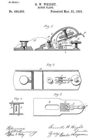
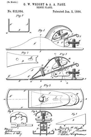
Figure 1, a view in side elevation of one form which a plane constructed in accordance with our invention may assume; Fig. 2, a plan view thereof; Fig. 3, a view thereof in central vertical longitudinal section on the line a–b of Fig. 2; Fig. 4, a view of the plane in transverse section on the line c–d of Fig. 3; Fig. 5, a view in transverse section through the stock of the plane on the line e–f of Fig. 1; Fig. 6, a detached view through the clamp of the plane on the line g–h of Fig. 2; Fig. 7, a detached plan view of the box or housing; Fig. 8, a similar view thereof in side elevation; Fig. 9, a detached reverse plan view of the secondary adjusting lever.

Our invention relates to an improvement in bench-planes, the object being to produce at a low cost for manufacture, a simple, light, durable and convenient article.

With these ends in view, our invention consists in a bench-plane having certain details of construction as will be hereinafter described and pointed out in the claims.

In carrying out our invention we form a stock A, from a single piece of heavy sheet-metal, which is struck into the required shape, the stock having the usual side flanges A’, and in addition thereto upturned end flanges A2 A2, into which the side flanges merge, as clearly shown by Figs. 1, 2 and 3 of the drawings. The stock thus formed will naturally have rounded side and end corners a, as shown in Figs. 4 and 5 of the drawings, that being an advantageous form, as such corners are less liable to mark or mar the article being planed than the sharp corners of planes having their stocks cast. The said stock is constructed with a transverse slot A3, located in the usual place, its rear wall of being beveled, as shown by Fig. 3 of the drawings.

Within the stock we locate a box or housing B, which we preferably strike up from a single piece of sheet-metal. This box may be said to be U-shaped in transverse section, and is arranged with its open side downward, as shown in Fig. 4 of the drawings, its edges being furnished with projecting lugs b b, by means of which it is secured to the stock A, the bottom of which is thereto provided with openings of suitable form to receive the said lugs. The box tapers gradually from its rear to its forward end, so as to form an inclined bed for the bit C, of the plane to rest upon. It also tapers laterally, growing wider from its rear to its forward end, so that it will form a wide bearing for the bit behind the cutting edge thereof. The vertical taper of the box is clearly shown by Fig. 8 of the drawings, while its lateral taper is seen in Fig. 7 of the same.

About midway the length of its inclined upper face or bed, the box is provided with a coupling-stud D, which stands at a right angle to the said bed. At its rear end the box is constructed with an elongated slot E, through which the teeth f of the primary adjusting-lever F, project, the said lever being hung upon a horizontal pin G, the ends of which are mounted in the sides of the box. Two thick washers G’ G’ located upon the said pin G, on opposite sides of the said lever F, prevent the same from lateral displacement on the pin. The outer end of the said lever is provided with an open longitudinal slot F’, which receives the knurled edge of an adjusting-nut H, mounted upon a threaded stud H’, secured in a vertical position to the rear end of the stock A. We do not, however, claim the said lever, nut or stud as new, for corresponding parts have been before employed for the same purpose in bench-planes. We have called the lever in question the primary adjusting lever because its function is to move the bit longitudinally to project its cutting edge from or withdraw it into the slot A3 for securing more or less depth of cut as required. The bit C is constructed upon its under face with a series of transverse grooves c, which are taken into by the teeth of the primary adjusting lever F, and which are located in the rear of its longitudinal slot C’, with which it is provided to adapt it to fit over the coupling-stud D, and be longitudinally adjusted. A secondary adjusting-lever I, projecting at its rear end slightly beyond the rear end of the bit, is pivotally attached to the lower face thereof by means of a screw I’, the forward end of the said lever being offset as at i, and then extended forward, whereby it is adapted to enter the open rear end of the box or housing B, with the side walls of which its forward edges engage to secure a purchase for the lateral adjustment of the bit, which it shifts to keep square with respect to the position of its cutting edge in the transverse slot A3 in the stock. The offsetting of this secondary lever in order to enable it to enter the rear end of the housing, will be proportional to the thickness of the metal from which the housing is formed.

We do not broadly claim a bit having a secondary adjusting lever secured to its lower face as described, except when its forward end is offset downward to adapt it to enter last the housing. We have called the lever described the secondary adjusting lever, because its function of laterally adjusting bit for squaring its edge in the slot in the the body of the stock seems secondary to the longitudinal adjustment of the bit.

The clamp J, of our improved plane, we prefer to strike from a single piece of sheet-metal in substantially the form which clamps of bench-planes ordinarily have, except as will be specified. Toward its forward end the clamp is constructed with an opening J’ , adapted in size to pass the head of the coupling-stud D, and with an open slot J2, leading forward from the said opening, and narrower than the same, the said slot being flanked on each side by horizontal flanges J3 J3, which form bearings for the head of the said stud. Under this construction the clamp is adjusted over the coupling-stud upon the bit, and then drawn rearward for locking it in place, and the more it is pushed rearward after it is in place, the tighter it will clamp the bit. This is an obviously advantageous construction, for when the plane is used, the tendency will be for the bit to be pushed rearward, and thus to only more firmly lock the clamp in place. In planes as ordinarily constructed, the operation of the clamp is just the reverse of this. The clamp is provided in its rear end with an internally threaded socket K, which receives an adjusting-screw L, which is staked, or otherwise secured into a sheet-metal hand-wheel M. The head L’ of the screw projects below the outer face of the wheel in position to be engaged with the upper face of the bit to the rear of the slot C’ therein, in the ordinary manner.

In our improved plane as herein described, the stock, the housing or box located therein to form a bed for the bit, the clamp, and the hand-wheel are struck from sheet-metal. We would have it understood, however, that we do not limit ourselves to using the said parts in combination, but we may use any one of them, or any combination of them. By constructing the said parts of sheet-metal, we secure lightness and rigidity, and an increase of room within a plane of given size. We are also enabled to give the plane pleasing lines, and to produce it at a comparatively low cost for manufacture, and obviously the sheet-metal enables it to be given at a comparatively small expense, a very high finish. Nor do we limit ourselves to the particular construction and arrangement of parts shown and described, for the devices represented for adjusting the bit both longitudinally and laterally, may be replaced by other devices.

We would therefore have it understood that we do not limit ourselves to the construction herein shown, but hold ourselves at liberty to make such variations therefrom as fairly fall within the spirit and scope of our invention. We are aware, however, that we are not the first to utilize sheet-metal in the construction of bench-planes, a plane having a wooden stock reinforced by a wrought metal covering being old.

Having fully described our invention, what we claim as new, and desire to secure by Letters Patent, is —

1. A bench-plane having its clamp struck out from a single piece of sheet-metal, and provided within its rear end with an internally threaded socket, which receives the adjusting screw carrying the hand-wheel, and constructed at its forward end with an opening, and with an open slot leading forward from the said opening and narrower than the same, the said slot being flanked on either side by flanges set inward from the face of the clamp, substantially as described.

2. A bench-plane having its clamp constructed with an opening to receive the coupling-stud of the plane, and with an open slot narrower than the said opening, extending forward therefrom and flanked on each side by horizontal flanges set down below the face of the clamp, substantially as described.

3. A bench-plane having a sheet-metal stock, having up-turned side and end flanges, a sheet-metal box or housing secured thereto with its open side downward, by means of lugs formed upon its lower edges, inclining and widening fromits rear to its forward end and forming an inclined bed for the bit, a bit and a wide bearing just back of the cutting edge thereof, a sheet-metal clamp, a clamping-screw carried thereby, and means for adjusting the bit longitudinally and laterally, substantially as described.

In testimony whereof we have signed this specification in the presence of two subscribing witnesses.

GRANVILLE W. WRIGHT.
ALBERT A. PAGE.

Witnesses:
ROBERT MACARTHUR, Jr.,
JOHN B. FREYSINGER, Jr.

No. 493,903 – Bench-Plane (Granville W. Wright) (1893)

[paiddownloads id=”489″]493903


UNITED STATES PATENT OFFICE.

_________________

GRANVILLE W. WRIGHT, OF NEW HAVEN, CONNECTICUT,
ASSIGNOR TO THE SARGENT & COMPANY, OF SAME PLACE.

BENCH-PLANE.

_________________

SPECIFICATION forming part of Letters Patent No. 493,903, dated March 21, 1893.
Application filed October 19, 1891. Serial No. 409,156. (No model.)

_________________

To all whom it may concern:

Be it known that I, GRANVILLE W. WRIGHT, of New Haven, in the county of New Haven and State of Connecticut, have invented a new Improvement in Bench-Planes; and I do hereby declare the following, when taken in connection with accompanying drawings and the letters of reference marked thereon, to be a full, clear, and exact description of the same, and which said drawings constitute part of this specification, and represent, in —

Figure 1, a longitudinal central section of the plane complete; Fig. 2, a top or plan view of the stock with the bit removed; Fig. 3, an under side or rear view of the bit; Fig. 4, a transverse section cutting on line x–x of Fig. 1 looking forward.

This invention relates to an improvement in that class of bench-planes in which the stock is made from metal, and in which the bit is made mechanically adjustable both as to depth of cut and as to transverse position, and particularly to those planes of this class in which the bit is single, that is without an adjustable cap upon its face. In the more general construction of planes of this character the transverse adjustment of the bit to vary its edge with relation to the face of the stock, is produced by a lever hung in the stock below the bit, the lever constructed with a projection which will extend up into a notch or slot in the bit, consequently the wear to which the bit may be subjected is considerably limited, as after a little wear, the point of engagement of the bit with the adjusting lever will have passed so far down from the lever as to prevent such engagement, consequently after a little wear the bit must be exchanged for a new bit with which the adjusting-lever may engage.

The object of my invention is to provide the lever a laterally adjusting arrangement, but so as to make the extent of wear to which the bit may be subjected unlimited so far as the adjusting device is concerned, and it consists in the construction hereinafter described and particularly recited in the claims.

A, represents the stock, of usual construction, B, the bit which is adapted to rest upon the bed below, in the usual manner, and upon its upper side is arranged a clamping lever C, which engages with a screw D, from the bed, through a slot in the bit, and between the bit and the lever above or in rear of the screw D, an adjusting-screw E, is arranged provided with a head F, by which it may be rotated. One end of the screw is threaded into a corresponding nut in the lever C, and the other end bears upon the upper side of the bit, so that by turning the screw, the bit will be clamped upon its bed, or released therefrom, accordingly as the screw is turned in one direction or the other, a common and well known device for securing the bit in place.

Upon the under side of the bit a toothed rack G, is formed, into which the teeth H, of a segment or lever H’ hung upon an axis I, below the bit work, the hub of the segment extending rearward, forms an arm J, by means of which the segment may be swung in a longitudinal plane for the adjustment of the bit to produce a greater or less extent of depth of cut. The segment is operated by means of an adjusting-screw K, in a well known manner. Upon the under side of the bit a lever is hung directly to the bit, upon a pivot L. As here represented the lever is of thin metal, and the pivot is screwed through a corresponding hole in the lever into the bit, so as to permit the lever to swing freely. One arm M, of the lever extends rearward, and terminates in a suitable handle N, the other arm O, extends downward below the pivot L, and as seen in Fig. 3. On the stock below the bit, a longitudinal recess is formed by two upwardly projecting ribs or long narrow posts P P, see Figs. 2 and 4. These ribs are parallel with each other and with the plane-stock with respect to the length thereof, and have their upper edges correspondingly inclined forward to form the rear support of the plane-bit which has bearing upon them. The distance between the two ribs corresponds to the width of the end of the arm O, of the laterally adjusting lever, so that when the bit is set in place, the lower end of the arm O, will stand in the recess between the two ribs P P so that these ribs will form a fulcrum, upon which the lever may swing to the right or left, and as the lever is so swung, as indicated in broken lines Fig. 3, the fulcrum end of the arm O, being held fast in the recess between the ribs P P, it follows that the pivot L, will be moved accordingly, and that the end of the bit will be turned to the right or left, and such turning of the bit changes the parallelism of the edge of the bit with relation to the plane of the face of the stock.

When lateral adjustment is required to bring the edge of the bit into the proper parallelism with the plane of the stock, the laterally adjusting lever is turned accordingly, as before described. It is to be observed that the two levers by which the squaring of the bit is effected and the depth of the cut is gaged, respectively, act entirely independently of each other so that the operation of one does not affect the operation of the other, the two levers having independent connection with the bit.

By hanging the lever directly to the bit instead of to the stock, it maintains always the same position with relation to the bit; as the bit wears away the lever simply extends farther downward into the recess within which its lower arm O, works, and so that the bit cannot get beyond the control of the lever because of the wearing away of the bit, as by grinding, &c. The construction is simple and very effective.

As herein shown, the axis or horizontal pin I, on which the segment or lever H’, is hung, is located between the said ribs or posts P P in a vertical slot P’, formed midway of the length of a web P2, which joins the said posts or ribs with which it is made integral.

From the foregoing it will be understood that I do not claim broadly a bench-plane having the bit laterally adjustable, but I am aware that planes have been constructed with a lateral adjusting lever hung to the under side of the bit, and so as to take its fulcrum on the stock, but in such case it has been necessary to make the lever adjustable on the bit, whereas by constructing the stock with a longitudinal recess within which the end of the lever may work as a fulcrum, the permanent hanging of the lever to the bit is made practicable. I do not therefore wish to be understood as broadly claiming hanging the lateral adjusting lever directly to the bit.

What I do claim as my invention, and desire to secure by Letters Patent, is —

1. In a bench-plane, the combination with a stock constructed at its rear end with a central longitudinal recess, of a bit, and an adjusting-lever pivotally attached to the outer end of the same, and extending rearward to be grasped for manual operation, and forward and downward to enter between and engage with the parallel side walls of the said recess at different points in the length thereof according to the position of the bit in the plane-stock, the said walls forming points of purchase for the operation of the lever in squaring the bit in the stock, substantially as set forth, and whereby the lever is always preserved in its right relation to the bit, although the same must constantly be moved forward in the stock as it becomes shorter through wear and grinding.

2. In a bench plane, the combination with a stock constructed at its rear end with two vertical ribs or posts extending parallel with each other and with the stock, and having their upper ends forwardly inclined correspondingly; of a bit having its rear support upon the said inclined upper ends of the said ribs or posts, an adjusting-lever mounted in the stock for vertical movement, and engaging directly with the bit which it adjusts vertically, and an adjusting lever pivotally secured to the rear end of the said bit, and extending rearward for manual operation and forward to enter between and engage with the said ribs or posts at different points in the length thereof according to the position of the bit in the stock, the said ribs forming points of purchase for the operation of the lever in squaring the bit in the stock, substantially as set forth, and whereby the said lever last mentioned is always preserved in its right relation to the bit, although the same must be constantly moved forward in the stock as it becomes shorter through wear, and grinding, whereby also the two levers act on the bit independently of each other.

3. In a bench-plane the combination with a stock constructed at its rear end with two vertical ribs or posts parallel with each other and with the length of the stock, having their upper ends forwardly inclined correspondingly, and joined by a vertically slotted web which is located between them; of a bit having its lower face provided with a longitudinal rack and having its rear support upon the said posts; an adjusting lever pivotally secured to the outer end of the said bit to the rear of the said rack, and extending rearward for manual operation, and forward to enter between and engage with the said posts or ribs at different points in the length thereof according to the position of the bit in the said stock, the said ribs forming points of purchase for the operation of the lever in squaring the bit in the stock; a lever pivoted in the vertical slot formed in the web between the ribs, and taking at its forward end into the rack formed in the lower face of the bit; and means for adjusting the said lever up and down, substantially as set forth, and whereby the adjusting lever pivoted to the bit is always preserved in its right relation thereto, although the same must constantly be moved forward in the stock as it becomes shorter through wear and grinding.

In testimony whereof I have signed this specification in the presence of two subscribing witnesses.

GRANVILLE W. WRIGHT.

Witnesses:
WILLIAM S. COOKE,
CHAS. L. BALDWIN.

No. 445,793 – Plane (Granville W. Wright) (1891)

[paiddownloads id=”472″]445793


UNITED STATES PATENT OFFICE.

_________________

GRANVILLE W. WRIGHT, OF NEW HAVEN, CONNECTICUT,
ASSIGNOR TO SARGENT & COMPANY, OF SAME PLACE.

PLANE.

_________________

SPECIFICATION forming part of Letters Patent No. 445,793, dated February 3, 1891.
Application filed October 6, 1890. Serial No. 367,226. (No model.)

_________________

To all whom it may concern:

Be it known that I, GRANVILLE W. WRIGHT, of New Haven, in the county of New Haven and State of Connecticut, have invented a new Improvement in Planes, (B;) and I do hereby declare the following, when taken in connection with accompanying drawings and the letters of reference marked thereon, to be a full, clear, and enact description of the same, and which said drawings constitute part of this specification, and represent, in —

Figure 1, a side view of the plane complete, a portion being broken away to illustrate the invention; Fig. 2, a top view of the same with the plane-iron removed.

This invention relates to an improvement in that class of planes in which the stock is made from metal, the stock being constructed with a seat upon which the plane-iron may rest, and provided with mechanism for clamping the iron upon the seat, and in which provision is made for adjusting the upper end of the plane-iron laterally in order to change the line of the cutting-edge of the plane-iron with relation to the face of the stock; and the invention particularly relates to the mechanism for making such lateral adjustment; and it consists in the construction, as hereinafter described and particularly recited in the claim.

A represents the stock, made from cast metal; B, the seat upon which the plane-iron rests; C, the throat through which the edge of the iron projects; D, the plane-iron; E, the clamp by which the plane-iron is secured, and F the adjusting-screw by which the plane-iron is adjusted up and down to decrease or increase the extent of cut. So far the plane is of common and well-known construction, and does not require particular description. The upper end of the seat B, on which the plane-iron rests, is recessed, and in the recess a lever G is arranged to lie directly behind the plane-iron, and swing transversely in a plane parallel with the plane-iron. On the seat is a stationary stud H, which forms the pivot for the lever G, the lever G being forked at its lower end to embrace the stud. Above the stud H in the bed a transverse slot I is formed. In the lever a stud J is fixed or made as a part of the lever, projecting from the face of the lever toward the plane-iron, the diameter or width of this stud corresponding to the width of the vertical slot in the plane-iron and so as to extend into that slot, as seen in Fig. 1. On the reverse side of the lever G is a like projection or stud K, which works in the transverse slot I, and so that as the lever swings to the right or left the said stud J will move with it, the stud J forming a guide or holder for the lever to retain it in place, the stud preferably having a head upon the under side of the slot I, as seen in Fig.1, so as to prevent accidental detachment of the lever from the stock. When the plane-iron is introduced, its slot passes over the stud J, and so that the stud J will stand within that slot, and when the plane-iron is secured in place if it be desired to adjust the line of the cutting-edge with relation to the face-plate the lever G is turned accordingly to the right or left, as the case may be, and as indicated in broken lines, Fig. 2, such movement of the lever throwing the upper end of the plane outward to the right or left, and correspondingly changing the angle of the edge of the plane-iron with relation to the face of the stock. Preferably the lever extends above the upper end of the plane-iron, so as to form a thumb-piece L, for the convenient adjustment of the handle; but this is not essential to the invention.

I do not wish to be understood as claiming, broadly, a plane having the lever arranged to swing transversely and in engagement directly or indirectly with the plane-iron, whereby the upper end of the plane-iron is transversely adjusted according to the swinging of said lever and the angle of the edge of the plane-iron thereby adjusted with relation to the face of the plane, as such, I am aware, is not new; but

What I do claim is —

In a plane in which the stock is constructed with a seat B, upon which the plane-iron D may rest and be secured, the seat provided with a stationary stud H, and constructed with a transverse slot I above said stud, combined with a lever G, hung upon said fixed stud and extending upward in a plane substantially parallel to the plane of the plane-iron, the said lever constructed with a stud J, corresponding to the slot of the plane-iron, and also with an stud K, extending into and so as to move in said transverse slot I, all substantially as and for the purpose described.

In testimony whereof I have signed this specification in the presence of two subscribing witnesses.

GRANVILLE W. WRIGHT.

Witnesses:
E. H. EGGLESTON,
W. S. COOKE.

No. 445,792 – Plane (Granville W. Wright) (1891)

[paiddownloads id=”471″]445792


UNITED STATES PATENT OFFICE.

_________________

GRANVILLE W. WRIGHT, OF NEW HAVEN, CONNECTICUT,
ASSIGNOR TO SARGENT & COMPANY, OF SAME PLACE.

PLANE.

_________________

SPECIFICATION forming part of Letters Patent No. 445,792, dated February 3, 1891.
Application filed October 6, 1890. Serial No. 367,225. (No model.)

_________________

To all whom it may concern:

Be it known that I, GRANVILLE W. WRIGHT, of New Haven, in the county of New Haven and State of Connecticut, have invented new Improvements in Planes; and I do hereby declare the following, when taken in connection with accompanying drawings and the letters of reference marked thereon, to be a full, clear, and exact description ot the same, and which said drawings constitute part of this specincation, and represent, in —

Figure 1, a side view with a portion of the plane-iron broken away to illustrate its connection with the adjusting-lever; Fig. 2, a top view with the plane-iron removed; Fig. 3, a face view of the plane-iron seat with the lever removed to show the transverse slot J and the slide therein.

This invention relates to an improvement in that class of planes in which the stock is made from metal, and in which provision is made for adjusting the upper end of the iron laterally, so as to change the angle of the iron with relation to the working-face of the stock, the invention relating particularly to the mechanism for producing such lateral adjustment; and it consists in the construction as hereinafter described, and particularly recited in the claim.

A represents the stock, which is made from cast-iron, and in which an inclined seat B is formed as a bed for the iron C, D representing the throat of the stock.

E represents the clamp by which the iron is held to its seat, all substantially as in the usual construction, and as here represented it is provided with an adjusting-screw F, by means of which the plane-iron may be raised or lowered to make the out less or more, as the case may be, also in the usual manner.

The particular mechanism as thus far described is too well known to require description.

The upper end of the seat B is recessed, and in the recess a lever G is hung upon a pivot H, and so as to swing in the plane of the seat B, on which the iron rests, this lever G lying directly back of the iron when in place, as seen in Fig. 1. Through the hub or body of this lever a segment-shaped slot I is formed eccentric to the pivot H, and as seen in Fig. Transversely across that portion of the bed in which the lever is hung is a slot J, (see Fig. 3,) in which a slide K is arranged, the said slide presenting a head L on the face adapted to stand in the vertical slot of the plane-iron, the width of the head being substantially the same as the width of the slot.

The said slide extends through the slot I of the lever G, and so that by turning the said lever G to the right or left the slide K will be moved transversely, according to the eccentricity of the slot I, and as indicated in broken lines, Fig. 2, and because the head L of the slide K stands in the slot of the plane-iron it necessarily follows that the upper end of the plane-iron is moved accordingly to the right or left, and such movement of the upper end of the plane-iron correspondingly turns the said iron to change its relation to the face of the plane, and so that the plane-iron may be adjusted to bring the line of its edge parallel with the face of the plane, or inclined thereto, as may be desired. The lever G preferably extends slightly above the upper edge of the plane-iron, so as to form a handle or thumb-piece, as M, by which it may be readily adjusted. When the plane-iron is secured to its seat and it is found necessary to change the line of the cutting-edge of the plane-iron with relation to the face of the plane, it is only necessary to turn the lever G to the right or left, as the adjustment may require, the clamp which secures the plane-iron to its seat being sufficient to hold it in place and yet permit such adjustment to be made, so that the adjustment may be made after the plane-iron has been firmly secured and without change of such securing devices.

From the foregoing it will be understood that I do not claim, broadly, a lever arranged in the stock back of the plane-iron as a means for adjusting the plane-iron transversely; but

What I do claim as my invention is —

In a plane substantially such as described, and in which the plane-iron is secured upon the seat in the stock, the stock constructed with a transverse slot above said seat and in rear of the plane-iron, a lever hung upon the stock in rear of the plane-iron and so as to swing in a plane parallel with the plane-iron and across said transverse slot, the lever constructed with a slot eccentric to the pivot on which it swings, and a, slide working in said transverse slot and extending through the said segmental slot of the lever into engagement with the plane-iron, substantially as and for the purpose described.

In testimony whereof I have signed this specification in the presence of two subscribing witnesses.

GRANVILLE W. WRIGHT.

Witnesses:
E. H. EGGLESTON,
W. S. COOKE.