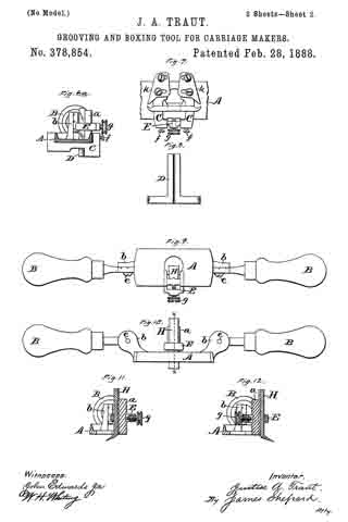
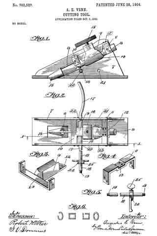
No. 763,527 – Cutting-Tool (Augustus E. Venn) (1904)

[paiddownloads id=”604″]763527


UNITED STATES PATENT OFFICE.

_________________

AUGUSTUS E. VENN, OF CHICAGO, ILLINOIS.

CUTTING-TOOL.

_________________

SPECIFICATION forming part of Letters Patent No. 763,527, dated June 28, 1904.
Application filed October 5, 1903. Serial No. 175,902. (No model.)

_________________

To all whom it may concern:

Be it known that I, AUGUSTUS E. VENN, a citizen of the United States, residing at Chicago, in the county of Cook and State of Illinois,have invented certain new and useful Improvements in Cutting-Tools, of which the following is a specification, reference being had to the accompanying drawings.

My invention relates to cutting-tools, and particularly to tools adapted to cut grooves in wood or other material to be operated upon; and its object is to provide a new and improved means by which, by the rotation of the cutter in the tool, grooves of different shapes may be cut in the work.

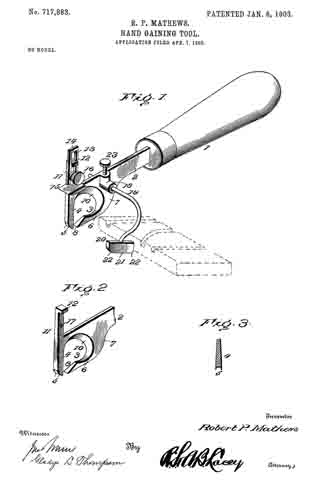
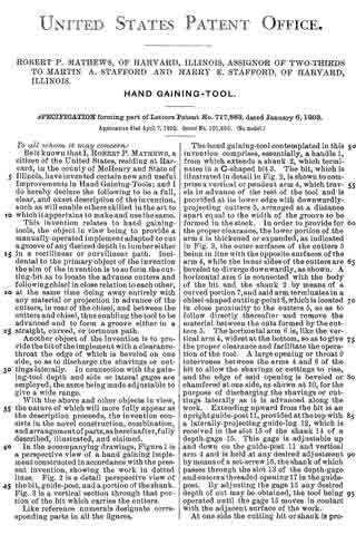
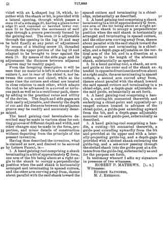
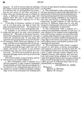
In the drawings, Figure 1 is a longitudinal vertical section on line 1 1 of Fig. 2. Fig. 2 is a top or plan view with one of the handles broken away. Fig. 3 is an enlarged detail, being an isometric view of a part of the support by means of which the cutter is secured to the stock. Fig. 4 is an enlarged detail, being an isometric view of a cross-bar by which one end of the support shown in Fig. 3 is secured to the stock. Fig. 5 is a detail, being a view of the gage, partly broken away; and Fig. 6 is a diagrammatic view showing several shapes which may be given to the cutting edge of the cutter.

As shown in the drawings and as preferably constructed, my invention is embodied in the form of a grooving-plane.

7 indicates the stock, and 8 the bit or cutter.

9 indicates a support which is provided with a cross-piece 10, preferably integral therewith, having its two ends bent up at right angles, as is best shown in Fig. 3, and of such length as to fit closely between the sides of the stock 7. The under side of the support 9 is rounded out, as is best shown in Fig. 3, to conform to the shape of the handle of the bit or cutter 8.

11 indicates a cross-piece which is bent at right angles at its ends and is of such length that the bent-up ends may fit snugly between the sides of the stock 7.

The support 9 is provided at the opposite end from the cross-piece 10 with a projection 12, and the cross-piece 11 is provided with a recessed portion 13 on its upper side, into which the projection 12 will snugly fit.

14 indicates a stirrup which is adapted to surround the rounded portion of the bit or cutter 8 and to pass around the support 9. It is provided on its upper surface with a screw-threaded opening into which a thumb-screw 15 may be screwed.

The bent ends of the cross-piece 10 and of the cross-piece 11 are provided with suitable screw-threaded openings by means of which they may be secured between the sides of the stock. The projection 12 of the support 9 is provided with screw-threaded openings and the recessed portion of the cross-piece 11 with corresponding openings, through which screws may pass to engage the screw-threaded openings in the projection 12 for the purpose of fastening the parts together.

The support 9 is placed between the sides of the stock with its hollowed rounded surface facing downward and is secured to the stock by suitable screws passing through the sides of the stock and into the screw-threaded openings in the bent ends of the cross-piece 10. The stirrup 14 is then placed in position around the support 9, the cross-piece 11 placed in position and fastened by screws to the sides of the stock, and the projection 12 is secured in place in the recess 13 by means of suitable screws.

The bit 8 is cylindrical at its upper end and is provided at its lower end with a cutting portion 16. The bit is provided with a proper clearance above the cutting portion, through which the shavings may pass, as is best shown in Fig. 2.

The cutting edge of the tool may be of various shapes, of which several are illustrated in Fig. 6. The cutter, being placed in position between the support 9 and the stirrup 14, may be adjusted longitudinally of itself, so that a proper amount of the cutting edge may project below the sole of the stock 7 through the usual opening therein, and is locked in position by turning the thumb-screw 15, which will cause the stirrup 14 to move up toward the support 9, firmly binding the cylindrical portion of the cutter between the stirrup and the support. It will be obvious that by rotating the cutter 8 upon its longitudinal axis, which it is obvious can be accomplished by loosening the set-screw 15 and then screwing it home when the desired amount of rotation is made, a different-shaped cutting edge will project below the sole of the stock 7 and a different-shaped groove thereby cut in the work.

17 (see Fig. 2) indicates handles, of which one is cut away upon one side to show the gage hereinafter described. The handles are secured to the stock in any appropriate way.

18 indicates a pin which is cylindrical in shape and has upon its ends screw-threaded portions 19. The sides of the stock 7 are provided with cylindrical openings 20 21, through which the cylindrical pin 18 may pass, and opposite the openings 20 21 are screw-threaded openings 22 23, which are adapted to engage with the screw-threaded ends of the pin.

24 indicates a gage which is provided with a suitable opening through which the pin 18 passes and which is secured in any desired position upon the pin 18 by means of a set-screw 25. It will be obvious that by this construction the gage can be used upon either side of the tool.

That which I claim as my invention, and desire to secure by Letters Patent, is —

1. The combination with a support, of a bit-iron mounted in said support adjustable longitudinally of itself therein and adapted to be rotated on its longitudinal axis and by its rotation to present a different-shaped cutting edge to the work, and means for locking said bit-iron in any desired position, substantially as described.

2. The combination with a plane-stock, of a bit-iron mounted in said stock adjustable longitudinally of itself therein and adapted to project its cutting edge below the sole of said stock, said bit-iron being rotatable on its longitudinal axis and having a cutting edge of such shape that by said rotation of said bit-iron grooves of different shape may be cut, and means for locking said bit-iron in any desired position, substantially as described.

3. The combination with a support of a cutting-tool adjustably mounted in said support adapted to be rotated on its longitudinal axis and having a tubular end provided with a cutting edge adapted by the rotation of said cutting-tool to present a different-shaped cutting edge tothe work, and means for locking said cutting-tool in any desired position, substantially as described.

4. The combination with a stock, a support secured to said stock, a stirrup surrounding said support, a set-screw carried by said stirrup adapted to bear upon one side of said support, a cutter having a shank adapted to be engaged between said support and said stirrup, said cutter being adapted to be rotated upon its longitudinal axis and having a cutting edge of such shape that by the rotation of said cutter grooves of different shape may be cut, substantially as described.

AUGUSTUS E. VENN.

Witnesses:
MINNIE A. HUNTER,
HELEN M. COLLIN.

No. 717,883 – Hand Gaining Tool (Robert P. Mathews) (1903)

[paiddownloads id=”577″]717883


UNITED STATES PATENT OFFICE.

_________________

ROBERT P. MATHEWS, OF HARVARD, ILLINOIS, ASSIGNOR OF TWO-THIRDS
TO MARTIN A. STAFFORD AND HARRY E. STAFFORD, OF HARVARD, ILLINOIS.

HAND GAINING-TOOL.

_________________

SPECIFICATION forming part of Letters Patent No. 717,883, dated January 6, 1903.
Application filed April 7, 1902. Serial No. 101,835. (No model.)

_________________

To all whom it may concern:

Be it known that I, ROBERT P. MATHEWS, a citizen of the United States, residing at Harvard, in the county of McHenry and State of Illinois, have invented certain new and useful Improvements in Hand Gaining-Tools; and I do hereby declare the following to be a full, clear, and enact description of the invention, such as will enable others skilled in the art to which it appertains to make and use the same.

This invention relates to hand gaining-tools, the object in view being to provide a manually-operated implement adapted to cut a groove of any desired depth in lumber either in a rectilinear or curvilinear path. Incidental to the primary object of the invention the aim of the invention is to so form the cutting-bit as to locate the advance cutters and following chisel in close relation to each other, at the same time doing away entirely with any material or projection in advance of the cutters, in rear of the chisel, and between the cutters and chisel, thus enabling the tool to be advanced and to form a groove either in a straight, curved, or tortuous path.

Another object of the invention is to provide the bit of the implement with a clearance-throat the edge of which is beveled on one side, so as to discharge the shavings or cuttings laterally. In connection with the gaining-tool depth and side or lateral gages are employed, the same being made adjustable to give a wide range.

With the above and other objects in view, the nature of which will more fully appear as the description proceeds, the invention consists in the novel construction, combination, and arrangement of parts,as hereinafter, fully described, illustrated, and claimed.

In the accompanying drawings, Figure 1 is a perspective view of a hand gaining implement constructed in accordance with the present invention, showing the work in dotted lines. Fig. 2 is a detail perspective view of the bit, guide-post, and a portion of the shank. Fig. 3 is a vertical section through that portion of the bit which carries the cutters.

Like reference numerals designate corresponding parts in all the figures.

The hand gaining-tool contemplated in this invention comprises, essentially, a handle 1, from which extends a shank 2, which terminates in a C-shaped bit 3. The bit, which is illustrated in detail in Fig. 2, is shown to comprise a vertical or pendent arm 4, which travels in advance of the rest ot the tool and is provided at its lower edge with downwardly-projecting cutters 5, arranged at a distance apart equal to the width of the groove to be formed in the stock. In order to provide for the proper clearance, the lower portion of the arm 4 is thickened or expanded, as indicated in Fig. 3, the outer surfaces of the cutters 5 being in line with the opposite surfaces of the arm 4, while the inner sides of the cutters are beveled to diverge downwardly, as shown. A horizontal arm 6 is connected with the body of the bit and the shank 2 by means of a curved portion 7, and said arm terminates in a chisel-shaped cutting-point 8, which is located in close proximity to the cutters 5, so as to follow directly thereafter and remove the material between the cuts formed by the cutters 5. The horizontal arm 6 is, like the vertical arm 4, widest at the bottom, so as to give the proper clearance and facilitate the operation of the tool. A large opening or throat 9 intervenes between the arms 4 and 6 of the bit to allow the shavings or cuttings to rise, and the edge of said opening is beveled or chamfered at one side, as shown at 10, for the purpose of discharging the shavings or cuttings laterally as it is advanced along the work. Extending upward from the bit is an upright guide-post 11, provided at the top with a laterally-projecting guide-lug 12, which is received in the slot 13 of the shank 14: of a depth-gage 15. This gage is adjustable up and down on the guide-post 11 and vertical arm 4 and is held at any desired adjustment by means of a set-screw 16, the shank of which passes through the slot 13 of the depth-gage and enters a threaded opening 17 in the guide-post. By adjusting the gage 15 any desired depth of cut may be obtained, the tool being operated until the gage 15 moves in contact with the adjacent surface of the work.

At one side the cutting bit or shank is provided with an L-shaped lug 18, which, together with the shank or bit, is provided with a lateral opening, through which passes a stem 19 of a side gage 20, having a plane lower edge 21 and rounded or beveled lower corners 22 to facilitate the movement of said gage through a groove previously formed by the gaining-tool. The stem 19 is adjustable through the opening in the lug 18 and may be held fixedly at any point of adjustment by means of a binding-screw 23, threaded through the upper portion of the lug 18 and adapted to be brought to bear against the stem 19. By means of the side gage and its adjustment the distance between adjacent grooves may be readily gaged.

From the foregoing description it will be seen that no material is left in advance of the cutters 5, nor in rear of the chisel 8, nor between the cutters and chisel, while at the same time the cutters and chisel are located in close relation to each other, which adapts the tool to be advanced in acurved or tortuous path as well as in a rectilinear path, thereby adding to the practical value and utility of the device. The depth and side gages are both easily adjustable, and thereby the depth of cut and the distance between the adjacent groove may be readily and accurately determined.

The hand gaining-tool hereinabove described may be made in various sizes for cutting grooves of different depth and width, and other changes may be made in the form, proportion, and minor details of construction without departing from the principle of the present invention.

Having thus described the invention, what is claimed as new, and desired to be secured by Letters Patent, is —

1. A hand gaining-tool comprising a shank terminating in abit of approximately C form, one arm of the bit being about at a right angle to the shank to occupy a perpendicular position when the said shank is horizontally arranged and terminating in spaced cutters, and the other arm curving away from, thence about parallel with the said shank toward the spaced cutters and terminating in a chisel-edge, substantially as described.

2. A hand gaining-tool comprising a shank terminating in a bit of approximately C form, one arm of the bit being about at a right angle to the shank to occupy a perpendicular position when the said shank is horizontally arranged and terminating in spaced cutters, and the other arm curving away from, thence about parallel with the said shank toward the spaced cutters and terminating in a chisel-edge, and a depth-gage adjustable on the vertical arm of the bit and in a direction at a right angle to the length of the aforesaid shank, substantially as specified.

3. In a hand gaining-tool, a shank, an arm and guide at the outer end of the shank extended in opposite directions therefrom about at a right angle, the arm terminatingin spaced cutters, a second arm curved away from, thence about parallel with the shank toward the said spaced cutters and terminating in a chisel-edge, and a depth-gage adjustable on the said guide, substantially as set forth.

4. A hand gaining-tool comprising a handle, a cutting-bit connected therewith and embodying a chisel-point and oppositely-arranged cutters located in advance of the chisel-point, a guide-post extending upward from the bit, and a depth-gage adjustably mounted on said guide-post, substantially as described.

5. A hand gaining-tool comprising a handle, a cutting-bit connected therewith, a guide-post extending upwardly from the bit and provided at its upper end with a laterally-projecting guide-lug, and a depth-gage provided with a slotted shank embracing the guide-lug, and a set-screw passing through the slotted shank into the guide-post at a distance from the guide-lug, substantially as and for the purpose set forth.

In testimony whereof I affix my signature in presence of two witnesses.

ROBERT P. MATHEWS. [L. S.]

Witnesses:
EUGENE SAUNDERS,
M. J. EMERSON.

No. 637,463 – Router (Reuben Hegarty) (1899)

[paiddownloads id=”541″]637463


UNITED STATES PATENT OFFICE.

_________________

REUBEN HEGARTY, OF BIGLER, CLEARFIELD COUNTY, PENNSYLVANIA,
ASSIGNOR OF ONE-THIRD TO PEARL T. DAVIS, OF CLEARFIELD, PENNSYLVANIA.

ROUTER.

_________________

SPECIFICATION forming part of Letters Patent No. 637,463, dated November 21, 1899.
Application filed March 18, 1899. Serial No. 709,562. (No model.)

_________________

To all whom it may concern:

Be it known that I, REUBEN HEGARTY, a citizen of the United States, residing at Bigler township, in the county of Clearfield and State of Pennsylvania, have invented certain new and useful Improvements in Routers; and I do declare the following to be a full, clear, and exact description of the invention, such as will enable others skilled in the art to which it appertains to make and use the same.

The invention has relation to routers.

The object of the invention is to provide a simple, durable, and inexpensive tool of this character which will perform its work in an efficient and rapid manner, making a cut on each stroke, both forward and backward.

With this object in view the invention consists in certain features of construction and combination of parts, which will be hereinafter fully described and claimed.

In the drawings, Figure 1 is a perspective view of my improved tool. Fig. 2 is a longitudinal sectional view through the cutting-head of the tool. Fig. 3 is an end view of the cutting-head of the tool. Fig. 4 is a modification.

In the drawings, 1 denotes the cutting-head of the tool, 2 its shank, and 3 its handle. The cutting-head of the tool is provided with two longitudinal vertical cutters 4 and with two chisel-shaped transverse end cutters 5 and 6, which are arranged above the cutting edges of the longitudinal cutters 4 and intermediate the extreme ends of said cutters 4.

In operation on the forward stroke of the tool the longitudinal cutters will make the vertical cut and the transverse cutter 5 will make the horizontal cut. On the return stroke of the tool the longitudinal cutters will make the vertical cut and the cutter 6 will make the horizontal cut. It will thus be seen that the tool cuts on its forward and backward stroke.

Various changes in the form, proportion, and the minor details of construction may be resorted to without departing from the spirit or sacrificing any of the advantages of this invention. For instance, if desired, the shank may be made straight, as shown in Fig. 4, and one (preferably the rear) transverse cutter rnay be dispensed with. Of course in this construction there would not be a cut at each movement of the tool.

Having thus described the invention, what is claimed, and desired to be secured by Letters Patent, is —

1. A tool consisting of a handle, a shank, and a cutter-head, the handle and shank projecting upwardly and rearwardly of the cutter-head, said cutter-head formed with longitudinal cutting edges and with transverse cutting edges arranged at either end of the head and above the longitudinal cutting edges, substantially as and for the purpose set forth.

2. A tool consisting of a handle, a shank, and a cutter-head, the handle and shank projecting upwardly and rearwardly of the cutter-head, said cutter-head formed with longitudinal cutting edges and with transverse cutting edges arranged at either end of the head above and between the sides of the longitudinal cutting edges, substantially as and for the purpose set forth.

3. A tool consisting of a handle, a shank, and a cutter-head, the handle and shank projecting upwardly and rearwardly of the cutter-head, said cutter-head formed with longitudinal cutting edges and with transverse cutting edges arranged at either end of the head and above and intermediate the ends of the longitudinal cutting edges, substantially as and for the purpose set forth.

4. A tool consisting of a handle, a shank and a cutter-head, the handle and shank projecting upwardly and rearwardly of the cutter-head, said cutter-head formed with longitudinal cutting edges and with transverse cutting edges arranged at either end of the head and above and intermediate the length and between the edges of the longitudinal cutting edges, substantially as and for the purpose set forth.

5. A tool consisting of a handle, a shank, and a cutter-head, the handle and shank projecting upwardly and rearwardly of the cutter-head, said cutter-head formed with longitudinal cutting edges and with a transverse cutting edge arranged at one of the ends of the head above the longitudinel cutting edges, substantially as and for the purpose set forth.

In testimony whereof I have hereunto set my hand in presence of two subscribing witnesses.

REUBEN HEGARTY.

Witnesses:
DENTON BEEMAN,
C. L. CORNELY.

No. 420,232 – Plane For Planing The Bottom Of Grooves In Moldings And Ornamental Wood-Work (Gustav Heÿmeier) (1890)

[paiddownloads id=”458″]420232


UNITED STATES PATENT OFFICE.

_________________

GUSTAV HEŸMEIER, OF BREMEN, GERMANY.

PLANE FOR PLANING THE BOTTOMS OF GROOVES
IN MOLDINGS AND ORNAMENTAL WOOD-WORK.

_________________

SPECIFICATION forming part of Letters Patent No. 420,232, dated January 28, 1890.
Application filed June 1, 1889. Serial No. 312,910. (No model.)

_________________

To all whom it may concern:

Be it known that I, GUSTAV HEŸMEIER, sculptor, of Bremen, in the Free State of Bremen and German Empire, have invented a new and useful Improvement in Planes for Planing the Bottoms of Grooves in Moldings and Ornamental Wood-Work, of which the following is a specification, reference being had therein to the accompanying drawings.

My invention relates to tools for planing the bottoms of grooves in moldings and ornamental wood-work, and has for its object to provide an effective tool for that purpose.

The invention consists in a plane of the character specified, constructed as hereinafter described and claimed.

Reference is to be had to the accompanying drawings, forming a part of this speciiication, in which similar letters of reference indicate corresponding parts in all the figures.

Figure 1 is a front view of the invention. Fig. 2 is a bottom view. Fig. 3 is a cross-section on the line A B of Fig. 1. Fig. 4 is a view of the blade with its guard-plate, and Fig. 5 is a cross-section of one of the handles of the tool on the line C D of Figs. 1 and 2.

The invention consists of a frame a, preferably hollow, as shown, and made of metal, and constituting the central portion a’ and the handles a2. On the bottom of the frame a is centrally located a plate b, secured by screws b’ to the central portion a’ of frame a. The plate b is provided with an opening b2, through which projects a blade c extending up through an opening b3 in the top of frame a, the blade c being movable through the openings b2 and b3. The blade c is clamped in fixed position by means of a shield-plate f also projecting through openings b2 and b3, and a screw g, passing through a washer g’, a slot g2 in frame a, over which the washer g’ extends, and a slot c’ in blade c, and engages plate f. By means of this construction the plate f and blade c may be adjustably raised and lowered and clamped in position. Within the central portion a’ is also located a vertical guide-piece e, projecting through an opening e’ in the plate b and opening e2 in the top of frame a, and vertically adjustable by means of a screw d engaging the guide-piece e and extending through a slot d’ in frame a, and a washer d2 overlapping the slot d’. The lower end of piece e projects in front of the projecting end of blade c, is in the form of a tooth, and is made of bone or other suitable material.

The piece e prevents the blade c from cutting too deeply into the wood.

The depth of the cavity to be planed is determined by the length of the blade c projected beyond the plate b.

The lower end of the plate f is formed with the rounded edge f’, and when the bottom of a groove is to be planed the plate f is adjustably lowered so as to bring its lower end down to the cutting-edge of the blade c, and the shape of the curved bottom of the groove is thereby retained while the tool is planing the bottom of the groove.

Having thus fully described my invention, l claim as new and desire to secure by Letters Patent —

A tool for planing moldings, consisting of the frame a, with handles a2, the removable plate b, with openings b2 e’, the vertically-adjustable curved shield-plate f, and the vertically-adjustable slotted blade c, projecting through opening b2, the binding-screw g, extending through slotted blade c and engaging plate f and the vertically-adjustable tooth e, projecting in front of the edge of blade c, and having the adjusting-screw d extending through the slot d’ in frame a, and the overlapping washer d2, substantially as shown and described.

In witness whereof I have hereunto set my hand in presence of two witnesses.

GUSTAV HEŸMEIER.

Witnesses :
EARNST BIERNRITH,
HUGO MÜHLENBACH.

No. 378,854 – Grooving And Boxing Tool For Carriage-Makers (Justus A. Traut) (1888)

[paiddownloads id=”430″]378854


UNITED STATES PATENT OFFICE.

_________________

JUSTUS A. TRAUT, OF NEW BRITAIN, CONNECTICUT, ASSIGNOR TO
THE STANLEY RULE AND LEVEL COMPANY, OF SAME PLACE.

GROOVING AND BOXING TOOL FOR CARRIAGE-MAKERS.

_________________

SPECIFICATION forming part of Letters Patent No. 378,854, dated February 28, 1888.
Application filed July 6, 1886. Serial No. 207212. (No model.)

_________________

To all whom it may concern:

Be it known that I, JUSTUS A. TRAUT, a citizen of the United States, residing at New Britain, in the county of Hartford and State of Connecticut, have invented certain new and useful Improvements in Grooving and Boxing Tools for Carriage-Makers, of which the following is a specification.

My invention relates to improvements in carriage-makers’ tools of the class usually termed “rooters;” and one object of my invention is to increase the utility and efficiency of the tool, so that it may do the work of several separate tools as heretofore constructed.
In the accompanying drawings, Figure 1 is a plan view of my tool in the form adapted to do the work of one style of rooter. Fig. 2 is a front elevation of the same, together with a piece of work. Fig. 3 is a reverse plan view of said tool. Fig. 4 is a front elevation of the same tool differently adjusted, so as to perform the work of another style of rooter, said figure also showing a piece of work. Fig. 5 is a side elevation of one side of one of the ears to which the handles are attached. Fig. 6 is a like view of that face of the handle which confronts the face of the handle-ears, Fig. 5. Fig. 6a is a transverse section on line y y, Fig. 1, of the stock of my tool, showing the other parts in side elevation. Fig. 7 is a reverse plan view of the middle portion of my tool, corresponding to Fig. 3, but with shoes or guides added thereto. Fig. 8 is a view showing the back side of the cutter for the rooter. Fig. 9 is a reverse plan view of my tool arranged for use as a boxer or paneling-tool. Fig. 10 is a front elevation of the same. Fig. 11 is a transverse section of the same on line x x of Fig. 10, and Fig. 12 is a like section of the same with the cutting-tool reversed.

A designates the stock of my implement, which stock is substantially a flat block with smooth under side and edges, having an upwardly-projecting tool-post, a, and handle-ears b b. For convenience of holding the handles B B in the desired positions, a rib, c, Fig. 5, is formed on the face of the handle-ears b b, and as many grooves, d, Fig. 6, are formed on the face of the handle-shank as may be desired, into either of which grooves the rib may enter to hold the handles in the desired position. The screw e serves as a pivot on which the handles turn after-the screw has been loosened sufficiently to let the rib c disengage the grooves. The screw alone might be depended upon to hold the handles in place; but by the use of the rib c and grooves there is less liability of displacement from any given adjustment. These screws e are substantially parallel with a transverse line across the under face of the stock, to enable the handles to be set for use in the relation to the under face of the stock shown in Figs. 1, 2, and 3, or as in Fig. 4. For most uses the handles will beset parallel with the stock A, as in Figs. 1, 2, 3, 9, and 10.

Side guides or gages, C C, are secured upon the stock A, the same being fitted to slide thereon and to be fastened in place, when adjusted, by means of the set-screws f. The stock A has an opening by the side of the tool-post a, through which the shank of the T-shaped tool D passes, said tool being held in position by the yoke E and its clamp-screw g. The two ends of the cross member of the T-shaped tool D are made hooked, as shown most clearlyin Figs. 3 and 7, to form, respectively, right and left hand cutters, either of which may be used. The shank of the tool is grooved longitudinally and fits a vertical rib on the side of the tool-post a. The gages G C can be set to have the ends of the cutters project a distance equal to the desired depth of cut.

F, Fig. 2, designates a piece of work such as the rooter is designed to groove, the implement being shown in said figure in position for forming said groove, the under face of the stock gaging the distance of the groove from the top of the work, while the gage C will gage the depth of cut. In starting a groove with the rooter, the cutter may be prevented from taking too rank a cut by canting the position of the tool with reference to the work, letting one handle fall backward and the other forward, so that the forward corner of one of the gages C may come against the work. As the groove deepens, the operator will give the tool a less canting position to feed the cutter in as fast as may be desired, until finally that part of the gage near the cutter bears on the work and the tool can cut no deeper without changing the gage.

If desired, shoes or guards k k may be secured to the under side of the gages C C just in front of the cutter, as shown in Fig. 7, so as to prevent the cutter from working too rank; but when the tool is used as above described these shoes are not essential.

In Fig. 4, G designates a piece of work of a different form, and in order to adapt the tool for this work the handles are adjusted into a position at right angles to the stock, so that the implement may be applied to the work as illustrated and then conveniently operated by the handles.

In Figs. 9, 10, 11, and 12 the implement is arranged for use as a boxer or paneling-tool. The T-shaped tool D and depth-gages C C are removed and the tool H substituted for the tool D. Like tools of varying widths are furnished, either of which may be used. This tool thus arranged may be used for sinking a box or panel or for smoothing the surface thereof. It will ordinarily be used as arranged in Figs. 9, 10, and 11; but sometimes for working in cramped places it may be desirable to secure the tool upon the other side of the tool-post a and reverse the position of the yoke E, as shown in Fig. 12.

I claim as my invention —

1. The combination of the stock A, having handles B B, the T-shaped cutter D, having a cutting-edge at each end of its cross member, whereby right or left hand cuts may be made without special adjustment, mechanism for holding said cutter, and the gages C C, substantially as described, and for the purpose specified.

2. The combination of the stock, right and left gages and cutters adapted for use in cutting lateral grooves either on the right or left side of vertical faces, and the handles B B, pivoted on axes which are substantially parallel with a transverse line across the under face of the stock and adapted to be adjusted and secured at different angles to the stock, substantially as described, and for the purpose specified.

3. The herein-described convertible rooter and boxer, consisting of the stock A, having a flat under face, the rooting and boxing cutters fltted for separate application to the stock, clamping mechanism for holding either of said cutters with their cutting end projecting below the bottom face of the stock, and attachable and detachable transverse gages for attachment to the bottom face of the stock, substantially as described, and for the purpose specified.

JUSTUS A. TRAUT.

Witnesses:
JOHN EDWARD, Jr.,
JAMES SHEPARD.