No. 868,803 – Beading Or Molding Tool (Alphonse Pellrin) (1907)

[paiddownloads id=”648″]868803


UNITED STATES PATENT OFFICE.

_________________

ALPHONSE PELLRIN, OF DETROIT, MICHIGAN.

BEADING OR MOLDING TOOL.

_________________

868,803. Specification of Letters Patent. Patented Oct. 22, 1907.
Application filed January 28, 1905. Serial No. 243,162.

_________________

To all whom it may concern:

Be it known that I, ALPHONSE PELLRIN, a citizen of the United States of America, residing at Detroit, in the county of Wayne and State of Michigan, have invented certain new and useful Improvements in Beading or Molding Tools, of which the following is a specification, reference being had therein to the accompanying drawings.

This invention relates to improvements in beading or molding tools, and its object is to provide a simple, cheap and efficient device so constructed that the cutting bit or blade may be rotated or turned to advance one end of the lower or cutting edge ot the bit along the line of its travel to give the same a shearing cut, and also to provide simple means for adjustably holding the bit which may be readily attached or detached.

A further object of the invention is to provide the same with a detachable sole plate and with certain other new and useful features, all as hereinafter more fully described, reference being had to the accompanying drawings, in which

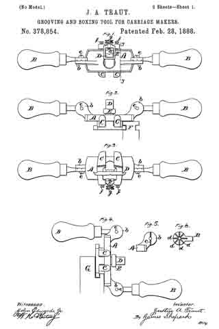
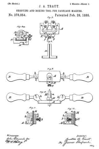
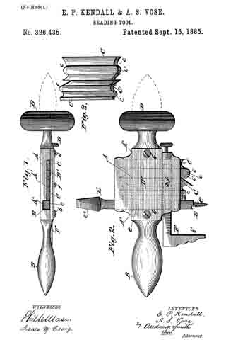
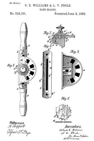
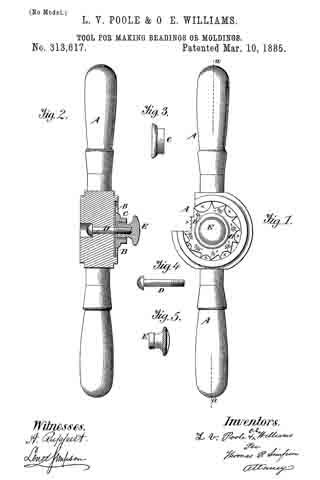
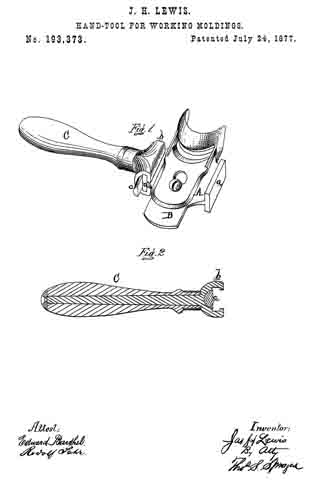
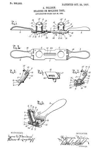
Figure 1, is a front edge elevation of a device embodying the invention and showing the same partly in longitudinal section; Fig. 2, is an inverted plan view ot the stock with all detachable parts removed; Fig. 3, is a side elevation of one of the knife or bit holders, detached; Fig. 4, is a perspective view of one of the sole plates, detached; Fig. 5, is an end view of the device with the handle broken away; and Fig. 6, is an enlarged perspective view of one end of the device showing the same in transverse section through the center of one ol the bit holders.

As shown in the drawing 1 is the stock of the tool consisting of a flat bar which is formed with a handle 2 at each end and with two circular openings 3, one near each end of the flat bar or stock, to receive the bit holders 4, each consisting of a casting formed with an upwardly extending inclined bed 5 for the knife or bit 6, and with a downwardly extending ring-shaped flange 7 to fit the circular opening 3 in the stock. The ring 7 is provided with an outwardly extending circular flange 8 to engage the upper surface of the stock and the holder is adjustably secured in the opening by providing an elongated slot 9 in said flange 8 to receive a screw 10 extending throughout and engaging a screw-threaded opening in the stock. Extending forward from the bed 5 at each side of the bit is the side flange 11, each of which is provided with a notch 12 extending downward from its upper end to receive laterally extending arms 13 on the clamping plate 14 which is provided with a screw-threaded opening near its upper end to receive a clamping thumb screw 15 adapted to extend through said opening and engage the bit, thus rocking said plate on its arms and causing the lower end thereof to press upon the bit and clamp the same firmly to its bed.

The lower end or cutting edge ot the bit 6 is shaped to give the article worked upon the desired form and a sole or wear plate 16 formed on its lower face to conform to the configuration of said cutting edge, is secured to the under surface of the stock over each opening 3 by providing said plate 16 with upwardly extending lugs 17 at one end, forming a dovetail opening between them to receive a dovetail rib 18 on the adjacent end of the stock, beneath the handle, and to further secure each sole plate in place, a screw 19 is provided. An opening 20 in said sole plate is provided for the end of the bit, through which it extends and which is of a size to permit the shavings to pass.

A longitudinal slot 21 is formed in the stock between the openings 3 and the lower face of the stock is cut away adjacent to said slot to term a longitudinal groove 22 to receive the stops 23 adapted to be adjusted along said groove and held therein by screws extending through the slot. These stops are provided to engage the edge of the board or other article being grooved or formed and cause the groove to be formed at the desired distance from the edge thereof.

For convenience the tool is provided with two bits or cutters but it is obvious that only one may be employed and by the particular construction of clamping plate but one screw is necessary and the plate and bit may be quickly removed by simply loosening the thumb screw.

By loosening the screws 10, the holders 4 may be turned within the openings 3 to set the blades or bits at an angle to the longitudinal axis of the stock or bar 1, so that one end of the cutting edge of each will cut in advance of the other end thereof and thus have a shearing action and so that the ends of said cutting edges may be moved nearer or farther from each other, thereby permitting line adjustment of the distance between the outer lines of the cut to be made.

Having thus fully described the invention what I claim is:

1. A routing tool comprising a stock adapted to be moved laterally across the work, a pair of bit holders each secured near one end of the stock, rotatable on an axis vertical to the plane of the stock, and each provided with a bit throat, a bit bed, a bit clamping plate and a bit having a cutting edge whose outer end projects beyond the body of the edge, so disposed that limited relative adjustment of the stock is obtained by the rotation of the bit holders, a guide slot between the bit holders in their axial plane, a gage plate for each bit holder adjustably secured in the slot, and a sole platefor each bit detachably interlocked with the stock outside of each bit holder, extending over and in register with the throat of the holder.

2. A routing tool comprising a narrow, substantially rectangular stock, adapted to be laterally moved across the work, handles on each end of the stock, integral therewith, a pair of bit holders, each consisting of a cylindrical base rotatably secured near one end of the stock vertically to the face of the stock, with its lower face flush with the stock face, means for clamping the holders in any desired angular relation to the stock, comprising a peripheral flange on the base, bearing on the upper side of the stock, a segmental slot in the flange, and a stud screw clamping the flange to the stock, passing through said slot, oblique means for securing a bit in each holder consisting of a bit bed extending obliquely up from the base, marginal, longitudinal flanges on the bed, longitudinally disposed grooves in the upper end portions of the flanges, a bit clamping plate provided with integral, alined lateral lugs between its ends, rocking and sliding in said grooves, and a thumb screw in the upper part of the clamping plate above the lugs, substantially perpendicular to the bed, means for centering the bit holders in relation to a neutral zone, consisting of a longitudinal slot in the stock between the bit holders in axial alinement therewith, whose margins in the stock bed are rabbeted to form a guide, gage plates for the bit holders, each provided with a longitudinal rib engaging the guide, adapted to center the bits in relation to a neutral surface between them, means for shielding bits in the holder comprising soles for each bit holder, each comprising a plate having an opening whose margins register substantially with the working edge of a bit, detachably held in alinement with a bit holder by a rib integrally fortned on the underside of the adjacent handle shank, adapted to dovetail with a lug integral with the plate, and a screw clamping the plate to the stock face over the bit holder.

3. A routing tool comprising a stock having a rectangular plane bed, handles integrally formed at each end thereof, a pair of bit holders in parallel spaced relation, each comprising a cylinder whose axis is perpendicular to the stock bed, each rotatably secured in an aperture in the bed near one end thereof, with their lower end faces flush with the bed, an annular flange on the upper end of each cylinder bearing on the upper side of the stock, a segmental slot in each flange, a screw passing through the slot, secured in the bed, a diametrically disposed throat opening in each cylinder, a lug extending obliquely from each cylinder, whose upper face is longitudinally grooved for a bit bed, a bit clamping plate, tiltably secured over each bed by integral, lateral lugs between the ends of the plate, sliding and rocking in parallel, longitudinal grooves in the side faces of the bed groove, a clamping thumb screw for each plate engaging a screw-threaded aperture in the upper end beyond the lugs, longitudinal, alined, undercut ribs on the under sides of the handle shanks, a shoe for each bit holder, provided with a lug adapted to detachably engage the adjacent undercut rib, and a countersunk screw engaging the stock, a longitudinal, rabbeted slot between the holders in their axial plane, an angle gage plate for each bit holder engaging said rabbeted slot, and a screw clamping each gage plate.

4. A routing tool comprising a stock, draw handles integrally formed at each end thereof, a bit holder rotatably secured at its lower end in the stock, axially perpendicular thereto, whose lower face is flush with the face of the stock, and is diametrically slotted to form a throat, a bit bed extending obliquely upward from the throat, parallel, longitudinal flanges on the sides of the bed integral with the holder, parallel slots in the upper parts of the flanges, a bit clamping plate provided with lateral alined lugs between its ends adapted to slide and rock in said grooves, a thumb-screw in the upper end of the plate transverse to the bed, a sole plate adapted to shield the projecting portion of the bit below the stock, a lug integral with the sole, detachably dovetailed to a rib integral with one of the handle-shanks beyond the end of the bed, a longitudinal guide slot in the bed between the bit holder and the other handle, and an adjustable gage for the bit longitudinally movable in said guide slot.

In testimony whereof I aflix my signature in presence of two witnesses.

ALPHONSE PELLRIN.

Witnesses:
OTTO F. BARTHEL,
THOMAS G. LONGSTAFF.

No. 378,854 – Grooving And Boxing Tool For Carriage-Makers (Justus A. Traut) (1888)

[paiddownloads id=”430″]378854


UNITED STATES PATENT OFFICE.

_________________

JUSTUS A. TRAUT, OF NEW BRITAIN, CONNECTICUT, ASSIGNOR TO
THE STANLEY RULE AND LEVEL COMPANY, OF SAME PLACE.

GROOVING AND BOXING TOOL FOR CARRIAGE-MAKERS.

_________________

SPECIFICATION forming part of Letters Patent No. 378,854, dated February 28, 1888.
Application filed July 6, 1886. Serial No. 207212. (No model.)

_________________

To all whom it may concern:

Be it known that I, JUSTUS A. TRAUT, a citizen of the United States, residing at New Britain, in the county of Hartford and State of Connecticut, have invented certain new and useful Improvements in Grooving and Boxing Tools for Carriage-Makers, of which the following is a specification.

My invention relates to improvements in carriage-makers’ tools of the class usually termed “rooters;” and one object of my invention is to increase the utility and efficiency of the tool, so that it may do the work of several separate tools as heretofore constructed.
In the accompanying drawings, Figure 1 is a plan view of my tool in the form adapted to do the work of one style of rooter. Fig. 2 is a front elevation of the same, together with a piece of work. Fig. 3 is a reverse plan view of said tool. Fig. 4 is a front elevation of the same tool differently adjusted, so as to perform the work of another style of rooter, said figure also showing a piece of work. Fig. 5 is a side elevation of one side of one of the ears to which the handles are attached. Fig. 6 is a like view of that face of the handle which confronts the face of the handle-ears, Fig. 5. Fig. 6a is a transverse section on line y y, Fig. 1, of the stock of my tool, showing the other parts in side elevation. Fig. 7 is a reverse plan view of the middle portion of my tool, corresponding to Fig. 3, but with shoes or guides added thereto. Fig. 8 is a view showing the back side of the cutter for the rooter. Fig. 9 is a reverse plan view of my tool arranged for use as a boxer or paneling-tool. Fig. 10 is a front elevation of the same. Fig. 11 is a transverse section of the same on line x x of Fig. 10, and Fig. 12 is a like section of the same with the cutting-tool reversed.

A designates the stock of my implement, which stock is substantially a flat block with smooth under side and edges, having an upwardly-projecting tool-post, a, and handle-ears b b. For convenience of holding the handles B B in the desired positions, a rib, c, Fig. 5, is formed on the face of the handle-ears b b, and as many grooves, d, Fig. 6, are formed on the face of the handle-shank as may be desired, into either of which grooves the rib may enter to hold the handles in the desired position. The screw e serves as a pivot on which the handles turn after-the screw has been loosened sufficiently to let the rib c disengage the grooves. The screw alone might be depended upon to hold the handles in place; but by the use of the rib c and grooves there is less liability of displacement from any given adjustment. These screws e are substantially parallel with a transverse line across the under face of the stock, to enable the handles to be set for use in the relation to the under face of the stock shown in Figs. 1, 2, and 3, or as in Fig. 4. For most uses the handles will beset parallel with the stock A, as in Figs. 1, 2, 3, 9, and 10.

Side guides or gages, C C, are secured upon the stock A, the same being fitted to slide thereon and to be fastened in place, when adjusted, by means of the set-screws f. The stock A has an opening by the side of the tool-post a, through which the shank of the T-shaped tool D passes, said tool being held in position by the yoke E and its clamp-screw g. The two ends of the cross member of the T-shaped tool D are made hooked, as shown most clearlyin Figs. 3 and 7, to form, respectively, right and left hand cutters, either of which may be used. The shank of the tool is grooved longitudinally and fits a vertical rib on the side of the tool-post a. The gages G C can be set to have the ends of the cutters project a distance equal to the desired depth of cut.

F, Fig. 2, designates a piece of work such as the rooter is designed to groove, the implement being shown in said figure in position for forming said groove, the under face of the stock gaging the distance of the groove from the top of the work, while the gage C will gage the depth of cut. In starting a groove with the rooter, the cutter may be prevented from taking too rank a cut by canting the position of the tool with reference to the work, letting one handle fall backward and the other forward, so that the forward corner of one of the gages C may come against the work. As the groove deepens, the operator will give the tool a less canting position to feed the cutter in as fast as may be desired, until finally that part of the gage near the cutter bears on the work and the tool can cut no deeper without changing the gage.

If desired, shoes or guards k k may be secured to the under side of the gages C C just in front of the cutter, as shown in Fig. 7, so as to prevent the cutter from working too rank; but when the tool is used as above described these shoes are not essential.

In Fig. 4, G designates a piece of work of a different form, and in order to adapt the tool for this work the handles are adjusted into a position at right angles to the stock, so that the implement may be applied to the work as illustrated and then conveniently operated by the handles.

In Figs. 9, 10, 11, and 12 the implement is arranged for use as a boxer or paneling-tool. The T-shaped tool D and depth-gages C C are removed and the tool H substituted for the tool D. Like tools of varying widths are furnished, either of which may be used. This tool thus arranged may be used for sinking a box or panel or for smoothing the surface thereof. It will ordinarily be used as arranged in Figs. 9, 10, and 11; but sometimes for working in cramped places it may be desirable to secure the tool upon the other side of the tool-post a and reverse the position of the yoke E, as shown in Fig. 12.

I claim as my invention —

1. The combination of the stock A, having handles B B, the T-shaped cutter D, having a cutting-edge at each end of its cross member, whereby right or left hand cuts may be made without special adjustment, mechanism for holding said cutter, and the gages C C, substantially as described, and for the purpose specified.

2. The combination of the stock, right and left gages and cutters adapted for use in cutting lateral grooves either on the right or left side of vertical faces, and the handles B B, pivoted on axes which are substantially parallel with a transverse line across the under face of the stock and adapted to be adjusted and secured at different angles to the stock, substantially as described, and for the purpose specified.

3. The herein-described convertible rooter and boxer, consisting of the stock A, having a flat under face, the rooting and boxing cutters fltted for separate application to the stock, clamping mechanism for holding either of said cutters with their cutting end projecting below the bottom face of the stock, and attachable and detachable transverse gages for attachment to the bottom face of the stock, substantially as described, and for the purpose specified.

JUSTUS A. TRAUT.

Witnesses:
JOHN EDWARD, Jr.,
JAMES SHEPARD.

No. 352,056 – Beading-Tool (Oscar E. Hildebrand) (1886)

[paiddownloads id=”417″]352056


UNITED STATES PATENT OFFICE.

_________________

OSCAR E. HILDEBRAND, OF NORWICH, CONNECTICUT.

BEADING-TOOL.

_________________

SPECIFICATION forming part of Letters Patent No. 352,056, dated November 2, 1886.
Application filed July 15, 1886. Serial No. 208,051. (No model.)

_________________

To all whom it may concern:

Be it known that I, OSCAR, E. HILDEBRAND, a citizen of the United States, residing at Norwich, in the county of New London and State of Connecticut, have invented certain new and useful Improvements in Beading-Tools, which improvements are fully set forth and described in the following specification, reference being had to the accompanying drawings, in which —

Figure 1 is a side view of said improved tool, and Fig. 2 a top view of the same. In Fig. 3 I have shown a transverse sectional view on line x x of Fig. 2.

My improvements are in that class of tools used commonly by cabinet makers and other wood-workers for grooving, channeling, or beading work, which cannot easily be done by machinery; and my object is to provide a practical tool, which shall be serviceable and strong, yet cheap.

My device is preferably constructed entirely of metal, the several pieces being of such shape I that they may be assembled with but little fitting.

Referring to the drawings, the letters a a’ represent rods, which are semicircular in cross-section and of sufficient length to receive at each end a handle, b, which handle I prefer to make of cast-iron. These handles are cored centrally throughout their length to slip over the two rods a a’, as will be understood by referring to Fig. 3, and are shaped at the irinner ends with flanges c c, which form gages to guide and control the movement of the knife when in use.

My cutting-tool proper is punched or otherwise formed from steel, and a single blank may have, if desired, several cutters of different designs on its opposite edges, as shown at d in Fig. 1. The cutter thus formed is entered between the flat sides of rods a a’, and the handles b are then adjusted to form the bead at the desired distance from the edge of the board, the depth of the cut being determined by the distance which the cutter projects below the rods. In order to clamp the parts thus adjusted firmly together, I have drilled and tapped the handles to receive clamping-screws e e, which, when screwed home, clamp the parts as rigidly as if they were integral with each other.

By forming my entire tool of metal, I find that the weight thus gained gives an impetus to the tool, which is desirable rather than objectionable, inasmuch as it requires less effort on the part of the operator. In many cases the thumb-screws e e may be dispensed with, the handles being forced onto rods a a’, which action squeezes the rods together sufficiently to hold the cutter; but as a rule I prefer to use clamping-screws, as shown.

Having described my invention, I claim —

1. In a beading-tool, in combination with two companion rods, a cutter adapted to be clamped between said rods, as described, and handles cored to slip over said rods to clamp the said cutters, all being substantially as herein specified.

2. In combination with two semicircular rods, a cutter adapted to be clamped between said rods, and handles cored to slip over said rods, as described, said handles being provided with clamping-screws, by which the several elements may be clamped together, for the purpose specified.

3. In combination with two companion rods, a cutter adapted to be clamped between said rods, as described, handles cored to slip over the ends of said rods and formed with gage-flanges at their inner ends, and thumb-screws or similar means for clamping the several parts together, substantially as herein set forth, and for the purpose specified.

OSCAR E. HILDEBRAND.

Witnesses:
FRANK H. ALLEN,
TYLER J. HOWARD.

No. 335,856 – Beading-Tool (Justus A. Traut) (1886)

[paiddownloads id=”405″]335856


UNITED STATES PATENT OFFICE.

_________________

JUSTUS A. TRAUT, OF NEW BRITAIN, CONNECTICUT, ASSIGNOR TO
THE STANLEY RULE AND LEVEL COMPANY, OF SAME PLACE.

BEADING-TO0L.

_________________

SPECIFICATION forming part of Letters Patent No. 335,856, dated February 9, 1886.
Application filed September 24, 1885. Serial No. 179,027. (No model.)

_________________

To all whom it may concern:

Be it known that I, JUSTUS A. TRAUT, a citizen ofthe United States, residing at New Britain, in the county of Hartford and State of Connecticut, have invented certain new and useful Improvements in Beading-Tools, of which the following is a specification.

My invention relates to improvements in hand beading-tools of the class which are similar to “spokeshaves;” and the objects of my invention are to simplify the construction of the tool, and at the same time to make it convenient and efiicient in use.

In the accompanying drawings, Figure 1 is a front elevation of my beading-tool. Fig. 2 is a plan view. Fig. 3 is a reverse plan view. Fig. 4 is a transverse section on line x x of Fig. 1. Fig. 5 is a detached plan view of one form of cutting-blade for my beading-tool, and Fig. 6 is a like view of another form.

A designates the body or middle portion of the stock, and B B the handles thereof. This middle portion is of angular form in cross-section, (see Fig. 4) and consists of two members — viz., a thin horizontal bed-plate, a, the under face of which is designed to bear upon the wood being beaded, and a cutter-supporting plate, b, which projects upwardly from the rear edge of the bed-plate and slants forward slightly, as shovvn. The cutter-blade c, having a slot or slots, as shown in Figs. 6 and 5, respectively, and having any desired form or forms of cutting-edge, I clamp to the front side of the supporting-plate b by means of bolt d and thumb-nut f. By “front side” I mean the side which faces forward and downward, and is nearest the bed-plate a. In this side of the plate is a pin or projection, g, Figs. 3 and 4, which rests in the slot of the cutter-blade c at the lower end, while the body of the clamp-bolt d passes through said slot at a point higher up, thereby holding the cutter firmly against swinging to either side, and, in case of a wide cutting-edge, presenting the same squarely to the work. Just above the under surface of the bed-plate a, and in rear of the cutter-blade below the pin g, the face of the cutter-supporting plate is beveled off a little, as shown in Fig. 4, in order that the cutter-blade may spring slightly, and thereby have less tendency to chatter. The cutters are made of steel which is thin enough to spring, thereby forming what may be termed “spring-cutters.”

The bed-plate is provided with an opening, through which the lower cutting-edge of the cutter-blade projects, as shown. This opening is not only large enough to let the cutter project through it, but is also large enough for the shavings or scrapings to pass through readily. The forward part of the bed-plate is provided with a longitudinal slot, which extends through the middle of the length of said stock, within which slot the guiding-lugs h of the gages k are fitted. Said gages are secured in place by rneans of screws n, and from the construction already described it is evident that the gages are adjustable to and from the cutter-blade. If the gage is slotted or cut away, as shown in Fig. 4, it may be slipped by the cutter-blade, when desired. Two of these gages may be employed, one at each side ot the cutter-blade, as shown in Fig. 3; but if one gage would be in the way, or for any reason, it may be removed, and the tool can be used with one gage only, as shown in Figs. 1 and 2.

The straight-edge of each gage is designed for use on straight work and work with a convex edge, while the rounding edge is designed for use on work having a concave edge. For such use the gage is set at the other end of the stock from that represented in Fig. 3, so as to bring the curved or convex side into position to face the edge of the cutter-blade.

By slotting or notching the upper edge of the gages at a point which is in longitudinal alignment with the cutter-blade, as shown in Fig. 4, I can readily slip the blade when loosened over the cutter, so as to bring it to either side thereof without removing the cutter- blade; or I may bring it partially over the cutter, so as to cover a part of its cutting-edge, and then I can use the exposed edge of the cutter for forming a bead or beads at the corner of a piece of work which corresponds to the exposed edge of the cutter.

I am aware that it is not new to use a cutter-blade having edges properly formed for beading or fluting in a stock similar to that of a spokeshave, and I hereby disclaim the same.

I am aware that a prior patent shows and describes a spokeshave having longitudinal slots at the junction of its handles and middle portion, within which slots gages were adjusted, said slots being upon each side of the cutter, and not extending in front of the cutter; also, that another patent shows and describes a bench-plane having a hinged cutter-supporting blade, the same being hinged to the bed-plate, and incidentally to its swinging motion the lower end was rounded off like the knuckles or hub of an ordinary hinge. Upon the front of this swinging bed was a rigid cutter-blade, with its end bent forward, and there was a slight space between the cutter and the lower end of the cutter-supporting plate, but not for any purpose analogous to the construction named in my third claim. All of said prior art is hereby disclaimed.

I claim as my invention —

1. The herein-described stock for a beading-tool, which consists of the handles B B and the intermediate middle portion, A, having the horizontal bed-plate a and the cutter-supporting plate b projecting upwardly from the rear edge thereof and slanting forward partially over the bed-plate, the seat for the cutter-blade being upon that side of the plate b which faces forward and downward, substantially as described, and for the purpose specified.

2. In a beading-tool, the combination of the upwardly-projecting cutter-plate b, slanting forward, as described, the bed-plate a, having the opening through which the cutter projects, and the longitudinal slot extending through the middle of the length of said bed-plate in front of the said opening for the cutter, the gage k at the under side of said bed-plate, the screw n upon the upper side of said bed-plate, for holding said gage, and the cutter-blade secured to that side of the cutter-plate which faces forward and downward, substantially as described, and for the purpose specified.

3. In a beading-tool, the bed-plate a, having the cutter-opening formed therein, and the upwardly-projecting cutter-supporting plate b, made integral therewith and slanting forward, as described, while its forward lower corner at the rear of said cutter-opening is cut away, in combination with a spring cutter-blade, c, made flat or straight, substantially as described, and for the purpose specified.

4. In a beading-tool, the combination of the stock having bed-plate a, slotted longitudinally through the middle of its length, the cutter-blade secured to said stock, and adapted to have its end project below the under face of said bed-plate, the gage extending transversely to said bed-plate, and having the slot or notch on its upper side at the point which is in longitudinal alignment with the cutter, and mechanism for holding the gage and adjusting it to various points along the longitudinal slot of the bed-plate, substantially as described, and for the purpose specified.

JUSTUS A. TRAUT.

Witnesses:
H. S. WALTER,
CHAS. B. STANLEY.

No. 326,435 – Beading-Tool (Elton P. Kendall And Ambrose S. Vose) (1885)

[paiddownloads id=”400″]326435


UNITED STATES PATENT OFFICE.

_________________

ELTON P. KENDALL AND AMBROSE S. VOSE, OF WINDSOR, VERMONT.

BEADING-TOOL.

_________________

SPECIFICATION forming part of Letters Patent No. 326,435, dated September 15, 1885.
Application filed March 28, 1885. (No model.)

_________________

To all whom it may concern:

Be it known that we, ELTON P. KENDALL and AMBROSE S. VOSE, both citizens of the United States, residing at Windsor, in the county of Windsor and State of Vermont, have invented certain new and useful lmprovements in Beading-Tools; and we do declare the following to be a full, clear, and exact description of the invention, such as will enable others skilled in the art to which it appertains to make and use the same, reference being had to the accompanying drawings, and to letters or figures of reference marked thereon, which form a part of this specification.

Figure 1 of the drawings is a vertical longitudinal seotion. Fig. 2 is a plan view. Fig. 3 is a detail view.

This invention relates to improvements in tools for cutting the beads and grooves of moldings and rosettes, and is adapted to be used on either wood, stone, or iron.

The invention consists, essentially, in firmly binding, edge to edge, in a metallic block a number of bar-shaped cutters or chisels, the cutting ends of which are formed and arranged to constitute the reverse of the contour of the molding, or one-half of the contour of the rosette to be formed.

The invention further consists in the construction of the cutting-edges of the chisels hereinafter described.

Referring to the accompanying drawings by letter, A represents a block of iron or steel, having on one of its side surfaces a shallow rectangular recess or out-away portion, A’.

A2 is a rectangular vertical recess in the floor of the recess A’, adjoining one side thereof, and for a purpose hereinafter explained.

B B are similar handles extending laterally from the side edges of the block A, and B’ is a plate adapted to be secured to the block A by the screws b b, so as to cover the recess A’ and bind the chisels, hereinafter described, between itself and the block in said recess.

C C, &c., are bar-shaped cutters or chisels of steel, rectangular in section, and with their sides parallel, so as to lie in the recess A’ with their sides pressed equally at all points by the block and plate B’. Their edges are also parallel, so that they will be bound together by the pressure of the set-screw D, which passes through a threaded opening in the edge of the block below the handle B on the edge opposite the recess A2.

The ends of the chisels may be made concave, convex, rectilinear at various inclinations, or of any desired contour; but whatever the contour of the end, its surface forms at all points a right angle with each side, so that the end has two cutting edges, c c, each of which has a pitch of ninety degrees. By this means the chisels may make either a draw cut or a push cut, according to the direction in which the block is moved, (the inclination being varied to suit the direction,) and, to complete the contour of the moldings, would make a draw cut and a push alternately.

The chisels, as is evident, are longitudinally adjustable, either separately or together in the block, and preferably have both ends provided with cutting-edges, as shown.

C’ is a modification of the ends of the chisels. In this case the vertical section of the end shows a U-shaped contour, the edges having a less pitch than ninety degrees.

One of the cutting-edges c may, if desired, be provided with the ricks c’ c’, to adapt it for certain kinds of work.

E is a bit having a rectangular shaft, e, and provided with the centering-point e’ and head e2’ on its lower and upper end, respectively. The shaft of the bit is held in the recess A2 by the plate B’, and its head is held for insertion into a brace or bit stock by which the bit and consequently the block and chisels are turned when forming a rosette. When the tool is used for moldings, the bit is removed and a rectangular shaft of the same diameter inserted in its place, against which shaft the chisels abut.

F is a gage-square laterally adjustable on the block by means of a proper slot and the set-screw f. The square is set so that its foot f’ will rest against the top or bottom of the molding and bring the chisels to the desired place. When turning rosettes,the gage-square is detached.

It is evident from the foregoing that any contour of molding or rosette may be formed by selecting the proper chisels and adjusting them to proper positions in the block A. Rosettes or moldings of different widths may be formed by binding on the block a greater or less number of chisels.

Having thus described this invention, what we claim is —

1. The improved beading-tool herein described, consisting of the holder-block A, recessed as shown, to receive the cutters, and having the recess E to receive the centering-bit, the plate or bar B’, adapted to secure the cutters and bit in their respective seats, and the set-screw D, passing through the threaded aperture in the holder-block to bind the cutters together, substantially as specified.

2. In a beading-tool, the combination, with the holder-block having the transverse recess to seat the cutters, of the plate B’, adapted to secure the cutters therein, and provided with a recess to receive a gage-square, the gage-square F, arranged at right angles to the cutters in the said recess, and the screw f, for adjustably securing the same therein, substantially as set forth.

In testimony whereof we affix our signatures in presence of two witnesses.

ELTON P. KENDALL.
AMBROSE S. VOSE.

Witnesses:
JOS. C. ENRIGHT,
GILBERT A. DAVIS.

No. 319,161 – Hand-Beader (Orlando E. Williams And Lawrence V. Poole) (1885)

[paiddownloads id=”395″]319161


UNITED STATES PATENT OFFICE.

_________________

ORLANDO E. WILLIAMS AND LAWRENCE V. POOLE, OF WINDSOR, VT.

HAND-BEADER.

_________________

SPECIFICATION forming part of Letters Patent No. 319,161, dated June 2, 1885.
Application filed March 28, 1885. (No model.)

_________________

To all whom it may concern:

Be it known that we, O. E. WILLIAMS and L. V. POOLE, of Windsor, in the county of Windsor and State of Vermont, have invented an Improved Hand-Beader, of which the following is a specification.

The special object of the invention is to make the tool and holder conveniently adjustable to either side of a stationary guide, so that it may be adapted to suit the grain of the wood and make central beadings in thick boards. This object is accomplished by constructing and combining the parts of a header, as hereinafter described.

Figure 1 of the drawings is a plan view; Fig. 2, a central cross-section; Fig. 3, a detail view of the cutter plate or holder, and Fig. 4 a detail view of the guide-piece. Fig. 5 shows a combination of cutters.

In the drawings, A represents the two-handed stock provided with the longitudinal groove a; B, the cutter plate holder having the longitudinal slot b to be arranged over the groove a. It also has a downwardly-extending flange, b’, to prevent lateral displacement and holes b2 b2 near the ends, so as to be secured to the stock by clamp-screws C C.

D is the cutter-plate, and E the cutter-disk, the latter clamped to the former by the thumb-nut e, headed screw e’, and washer e2. The screw e’ is passed with its point up through the slot D, while the opposite parallel sides of its head are within the groove and rest upon the ledges b3 b3. Thus it will be seen that the screw is locked so that it cannot turn, but can be slid along when the nut is loosened.

F is the guide, which is provided with a right-angled arm, f that is held by a screw, f’, to the stock A.

By loosening the nut e the cutter-disk and cutter-plate may be slid so as to bring the beader-points on either side of the guide F, as may be desired.

Having thus described all that is necessary to a full understanding of our invention, what we claim as new, and desire to protect by Letters Patent, is —

A hand-beader having a stock or handle that has a longitudinal groove in its upper side, a fixed guide secured near the center of stock on the front of it, a metal plate secured to the stock on its upper side and having a longitudinal slot corresponding with the groove in the stock and fitting over it, a screw with its head resting loosely in said groove and under said plate with its shank passing up through the slot in the plate, a cutter-plate and a cutting-disk resting successively above said metal plate, each having an opening to receive the shank of the screw, and a thumb-nut engaging the end of the screw, whereby the clamps may be so adjusted as to bring the beading-points on either side of the guide, as set forth.

ORLANDO E. WILLIAMS.
LAWRENCE V. POOLE.

Witnesses:
HUGH GILGHRIST,
H. M. HUBBARD.

No. 313,617 – Tool For Making Beadings Or Moldings (Lawrence V. Poole And Orlando E. Williams) (1885)

[paiddownloads id=”386″]313617


UNITED STATES PATENT OFFICE.

_________________

LAWRENCE V. POOLE AND ORLANDO E. WILLIAMS, OF WINDSOR, VERMONT.

TOOL FOR MAKING BEADINGS OR MOLDINGS.

_________________

SPECIFICATION forming part of Letters Patent No. 313,617, dated March 10, 1885.
Application filed November 28, 1884. (No model.)

_________________

To all whom it may concern:

Be it known that we, LAWRENCE V. POOLE and ORLANDO E. WILLIAMS, citizens of the United States, residing at Windsor, in the county of Windsor and State of Vermont, have invented a new and useful Tool for Making Beadings or Moldings, and that, according to our knowledge and belief, the same has not been in public use or on sale in the United States for more than two years prior to this application, and that the following is a specification thereof.

The objects of our invention are, first, to provide a means for making beadings or moldings on wood or other materials of different shapes and sizes with the same tool; second, to provide facilities for the proper adjustment and manipulation of the cutting-plate by which the beadings or moldings are formed. Work can be done with this tool, which now requires an expensive set of planes, and beadings or moldings can easily be fornied on irregular surfaces where it is not practicable to do such work with the planes now used for such purposes. We attain these objects by the mechanism illustrated in the accompanying drawings, in which —

Figure 1 is a view in elevation of the tool ready for use. Fig. 2 is a section of the tool on the line a a, showing its parts. Fig. 3 is a view of the washer shown at C. Fig. 4 is a view of the screw shown at D. Fig. 5 is a view of the nut shown at E.

Similar letters refer to similar parts throughout the several views.

A A is a handle or stock, made of wood or metal, and which may be made to be used with one hand or both, to which the cutting-plate B is attached by the screw D, nut E, and washer C.

A’ is a notch or recess in the body of the stock A A, to which the form of cutter desired to be used is turned when the tool is used.

B B is a cutting-plate, made of metal, which may be round, square, or many~sided, as desired, by which the beadings or moldings are formed, the various shapes of beadings or moldings desired being cut into the edge of the plate, as shown at the points marked X.

C is a washer, of metal, placed between the nut E and plate B,for the purpose of giving a firm bearing on the plate B. This washer may be dispensed with, if desired, and the bearing made directly by the thumb-screw E.

D is a screw passing through the handle A A, plate B, and washer C into the nut E.

E is a nut working on the screw D, by which the plate B is held in the position desired.

The tool is used in much the same manner as an ordinary shave or scraper; the form on the plate B which it is desired to make, having been placed in position at the recess A’, is pressed firmly onto the wood or metal where the bead or molding is desired, and worked back and forth till the bead or molding is cut to the desired depth.

We are aware that prior to our invention beadings or moldings have been cut by plates of metal in the edge of which the shape desired had been cut; and we do not therefore claim broadly the invention of that manner of making beadings or moldings; but

What we do claim as our invention, and desire to secure by Letters Patent, is —

I. ln a hand-beader, the tool-stock perforated centrally for a screw-clamp, having the tool-seat around said perforation, and provided with an angular recess, A’, the latter arranged in a plane at right angles to the plane of the seat, as shown, and for the purpose described.

2. A hand-beader having two diametrically-opposite handles, an intermediate centrally-perforated stock provided with recess A’, and a suitable screw-clamp, the tool-seat being arranged around said perforation, as shown, and for the purpose set forth.

LAWRENOE V. POOLE.
ORLANDO E. WILLIAMS.

Witnesses:
URIEL L. COMINGS,
WM. BATCHELDER.

No. 193,373 – Improvement In Hand-Tools For Working Moldings (James H. Lewis) (1877)

[paiddownloads id=”281″]193373


UNITED STATES PATENT OFFICE.

_________________

JAMES H. LEWIS, OF DETROIT, MICHIGAN.

IMPROVEMENT IN HAND-TOOLS FOR WORKING MOLDINGS.

_________________

Specification forming part of Letters Patent No. 193,373, dated July 24, 1877; application filed January 4, 1877.

_________________

To all whom it may concern:

Be it known that I, JAMES H. LEWIS, of Detroit, in the county of Wayne and State of Michigan, have invented an Improvement in Hand-Tools for Working Moldings, of which the following is a specification:

The nature of my invention relates to an improvement in hand-tools for working moldings, of which there is a great variety of shapes and sizes in a set; and has for its object to so construct the same that one pair of removable handles will fit and can be secured to any of the heads of the various tools.

The invention consists in the peculiar construction of the tool-heads and the handles, as more fully hereinafter set forth.

Figure 1 is a perspective view of one of my improved tools, with one handle detached. Fig. 2 is a longitudinal section through one handle.

In the drawing, A represents a metal stock or head, adapted to receive and have secured to it a bit, B, of the form to produce a given cross-section of molding. The head is cast at each side with a double-flanged rib, a, over which slides a T-slotted head, b, on the inner end of a wooden handle, C, which is secured thereon by driving in a taper key, c.

As hereinbefore stated, a full set comprises a great variety of forms and sizes of molding-tools, the heads alone of which take up but very little space in a joiner’s chest. In the present case one pair of handles will answer for the entire set, which costs less and takes up less space than a set with handles permanently attached.

What I claim as my invention is —

The head A of a hand molding-tool, cast with the flanged ribs a a and the handles C C, provided with the slotted heads b, adapted to be secured to said ribs by a taper key, c, driven in each, substantially as described.

JAMES H. LEWIS.

Witnesses:
H. F. EBERTS,
H. S. SPRAGUE.

No. 107,653 – Improvement In Tools For Cutting Wood-Moldings (Charles E. Boynton) (1870)

[paiddownloads id=”142″]107653


United States Patent Office.


CHARLES E. BOYNTON, OF SAN FRANCISCO, CALIFORNIA, ASSIGNOR TO
HIMSELF AND ISAAC N. VOSBURG, OF SAME PLACE.

Letters Patent No. 107,653, dated September 27, 1870.
_________________

IMPROVEMENT IN TOOLS FOR CUTTING WOOD-MOLDINGS.

_________________

The Schedule referred to in these Letters Patent and making part of the same.

_________________

To all whom it may concern:

Be it known that I, CHARLES E. BOYNTON, of the city and county of San Francisco, State of California, have invented an Improved Fluting and Beading-Tool for Wood-Workers; and I do hereby declare the following description and accompanying drawing are sufflcient to enable any person skilled in the art or science to which it most nearly appertains to make and use my said invention or improvements without further invention or experiment.

The object of my invention is to provide an improved tool for all fluting and beading, and more especially for finishing off the corners of coach and carriage-work; and

It consists, first, in a novel construction of the beader, whereby I am enabled to form several different moldings with one bead, and to use different beads in the same handle.

It also relates to an improved manner of fastening the bender in place, and to the use of a peculiar face-plate, so that the quality of the work and the permanency of the tool are much improved.

Referring to the accompanying drawing for a more complete explanation of my invention —

A is a handle, which is made of suitable shape and size to be easily grasped by a hand at each end; and it has a slot, B, made through the middle, of sufficient size to admit the header easily and give plenty of space to clear itself of shavings.

To the under side of this handle is fixed a face-plate, C, which is made with two jaws, a a, between which the handle is set and firmly fixed.

A lip or portion of the plate, D, extends far enough out in front of the rest of the handle to make a bearing-surface, and prevent the handle from rolling in the hand. It also saves much wear.

A guide, D, projects below the face-plate, and an extension, e, of this guide, into the slot B on one side, serves as a nut for the holding-screw E.

The beader F may he constructed with any number of slots, c c, and will have as many beading or fluting-edges.

The slots fit down over the guide D far enough to allow the fluter to appear below the face-plate, when it is firmly fixed by turning up the holding-screw E.

The fluting-edges d d are formed around the circumference of a steel plate, as shown, and are made of any of the common or most useful forms. They are made in pairs, one of each pair standing upon either side of the guide, so that one or the other may be used, as the position of the work makes it most convenient.

If the beader is made with four, or six, or other number of cutting-edges, it will have the same number of slots c. Any number of beads may be fitted and employed with a single handle, but with two the workman will have ten or twelve different beads, which will usually be sufficient.

Having thus described my invention, What I claim as new, and desire to secure by Letters Patent, is —

1. The beading-tool F, with one or more different fluters or sets of cutting-edges, d d, substantially as and for the purposes herein described.

2. The face-plate C, with its jaws a a, and lip b, substantially as and for the purpose described.

In witness that the above-deseribed invention is claimed by me, I have hereunto set my hand and seal.

CHARLES E. BOYNTON. [L. S.]

Witnesses:
M. W. ALLEN,
E. F. MOORE.