No. 529,681 – Carpenter’s Plane (Henri Foucault) (1894)

UNITED STATES PATENT OFFICE.
_________________
HENRI FOUCAULT, OF CANTON, ASSIGNOR OF ONE-HALF TO E. BLOCH & CO, OF CLEVELAND, OHIO.
CARPENTER’S PLANE.
_________________
SPECIFICATION forming part of Letters Patent No. 529,681, dated November 20, 1894.
Application filed July 28, 1894. Serial No. 518,831. (No model.)
_________________
To all whom it may concern:
Be it known that I, HENRI FOUCAULT, a citizen of the United States, residing at Canton, in the county of Stark and State of Ohio, have invented certain new and useful Improvements in Carpenters’ Planes; and I do hereby declare that the following is a full, clear, and exact description of the invention, which will enable others skilled in the art to which it appertains to make and use the same.
My invention relates to carpenters’ planes, and the invention consistsin the mechanism and combination substantially as shown and described and particularly pointed out in the claims.
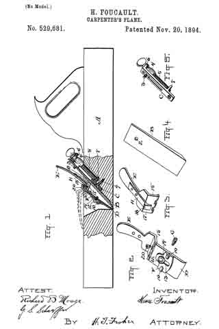
In the accompanying drawings, Figure 1 is a side elevation of aplane containing my improvements and having the central portion thereof broken away and the mechanism sectioned vertically to more fully disclose the construction and arrangement of parts. Fig. 2 is a perspective front elevation of the brake iron and locking mechanism of the bit, and Fig. 3 is a perspective rear elevation of the upper section shown in Fig. 2. Fig. 4 is a perspective elevation of the bit itself. Fig. 5 is a perspective elevation of the adjusting mechanism and support for the bit.
A represents the stock of the plane, and B the bit or plane iron. This iron or bit has a perforation or hole –2– near its top which engages a pin –3– on the threaded nut –4– on the adjusting screw –5– having bearings –6– and –7– on the back of the slotted supporting piece C. This adjusting and supporting piece C has a longitudinal slot through which the pin –3– projects, and the said piece is fastened firmly in the stock and made rigid therewith by means of a screw –9– at its bottom or the equivalent thereof. By turningthe adjusting-screw –5– the nut –4– and pin –3– of course would be caused to travel up or down according as said screw is turned and will carry the bit B in either direction, as may be desired. The bit is therefore fed or withdrawn by this adjusting mechanism and it may be set at any point desired or be in a little less or little deeper cut, as the work may require. Now, having the bit thus supported and adjustable, I provide simple and speedy locking mechanism therefor consisting primarily of the parts D and E. The part D is the usual brake iron, and this brake iron is held in position in the stock by means of a support F which is a separate piece and has sockets –10– at its side which are engaged through the sides of the stock by threaded pins G, the inner extremities of said pins engaging in the sockets –10–. The iron D and the said supporting piece F are then fastened together by means of a screw –12–, Fig. 1, which passes through the vertical slot –13– in the support F and enters a threaded hole in the iron D, a washer –14– being interposed upon which the head of the screw is adapted to bear. The said iron D is therefore held adjustable in the support F and may be placed in higher or lower position with respect to the blade or the bit, as may be desired. In operation, the iron D and the support F are really pivoted upon the pins or trunnions G and hence the bit B is held firmly against its back support at two points as is clearly shown in Fig. 1. Now, in order that the said bit maybe secured and removed with ease and speed and firmly held when in use, I employ the lever E which has a forwardly projecting portion –15– at its bottom at right angles substantially to its handle portion and hinged along its edge to the top of the iron D. Upon the rear and centrally of this handle E, I attach a separate member H which likewise is formed with an inwardly extending portion –17– at its bottom and with a heel –18– which is designed to operate on the principle of a cam in its engagement and effect in locking and holding the bit B. The said part H is rigidly fixed to the handle E and an adjusting screw –20– is threaded through the part E at its bottom and engages against the inner portion –17– of the said part H, so that it may be pressed backward more or less according as more or less pressure is required upon the bit. I might fashion the part E with a heel or cam portion to bear directly against the bit, butI have found that it is desirable to have an adjustment at this point owing to different thicknesses of bits and other changing or varying conditions which render such adjustment of the locking member desirable.
In operation, the bit is locked when the parts are in the position as seen in full lines in Fig. 1, and itis unlocked and may be taken out by simply removing it from the pin –3– when the lever E is moved forward into the position shown in dotted lines Fig. 1. It will of course be observed that since the blade D is pivoted on its support the sharp edge thereof at the bottom will be thrown back against the bit at that point when the lever E is forced against the bit at the top so that the bit is locked at two places and firmly held therein. It may, however, be adjusted by turning the screw –5– notwithstanding the fact that it is locked but usually the adjusting occurs when the lever E is open and it is the work of but an instant to open or close said lever and to remove or replace the bit.
What I claim is–
l. In planes, the plane stock, a pivoted support for the brake iron having sockets in its sides and pins through the sides ofthe stock in said sockets and serving as pivot points, a brake iron adjustably attached to said support, a locking lever for the bit pivoted at the top of said brake iron, and the bit held by said lever, substantially as set forth.
2. A plane stock and a bit supported adjustably therein, a pivoted brake iron and a pivoted locking lever on the top end of said iron having an adjustable cam shaped heel to engage the bit and a set screw to adjust said heel, substantially as set forth.
3. The stock and the bit and a support for the bit at its rear having a pin tlirough which the bit is held, in combination with the brake iron, a pivoted support therefor having trunnions –10– and a slot, and a set screw –12– engaging the brake iron through said slot, whereby said iron is adjusted, and a lever E pivoted to the top of said iron and provided with a heel –15– to bear against the fare of the bit above the pivot point of the brake iron, substantially as set forth.
Witness my hand to the foregoing specification.
HENRI FOUCAULT.
Witnesses:
S. SIMONS,
JOHN ROLLI.


