
No. 122,609 – Improvement In Carpenters’ Planes (Henry A. Holt) (1872)

UNITED STATES PATENT OFFICE.
_________________
HENRY A. HOLT, OF WILTON, NEW HAMPSHIRE.
IMPROVEMENT IN CARPENTERS’ PLANES.
_________________
Specification forming part of Letters Patent No. 122,609, dated January 9, 1872.
_________________
To all whom it may concern:
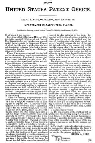
Be it known that I, HENRY A. HOLT, of Wilton, in the county of Hillsborough and State of New Hampshire, have invented certain new and useful Improvements in Carpenters’ Planes, of which the following is a full, clear, and exact description, reference being had to the accompanying drawing making part of this specification, in which —
Figure 1 represents a central longitudinal section of an ordinary bench~plane containing my improvement. Figs.2 and 3 represent the improvement detached from the plane. Fig. 4 represents, also, a section of a plane and certain modifications of my invention.
This invention relates to certain improvements in the bench-planes used by carpenters and other wood workers, whereby the face of the plane is slightly elevated above the material being planed, to prevent dragging the iron and dulling its cutting-edge when drawing the plane backward.
This invention consists of a spring, actuated and yielding disk or plate g, applied to the face of the plane and projecting a little beyond its surface and actuated by a spring, f to press the disk outward and hold the face of the plane a little above the surface of the material being reduced. The apparatus may be applied either back of the iron or forward ofthe iron, as shown in the drawing.
In the said drawing, A represents the plane-stock or wood provided with the usual plane-bit B and a wedge, C, or other device for holding the bit or plane-iron. At any convenient distance, either forward or back of the cutting-edge of the bit, a metal flange, b, is inserted in the face of the plane, either on a line with its face surface or a little beyond it, as shown, and this flange b is fastened to the plane-stock generally by screws. The flange b has a central opening, and above this is a bail or brace, d, rising from the flange. The disk or plate g is applied within the flange b, fitting loosely in the aperture. A stem or spindle, n, rises above the plate, and its upper end is furnished with a nut, e, or other equivalent means for adjusting the plate, between which and the under side ofthe bail or stirrup d I apply a spring, f, which may be adjusted or regulated to produce the desired downward pressure upon the disk, and keep it beyond the face of the plane, the face of the disk being somewhat rounded to prevent its edge catching in the wood. Instead of applying the adjusting nut e at the top of the stem this nut may be applied near the roots of the stem above the plate g’, and the spring f applied between the top of the nut and the under side of the stirrup; but in this case the stirrup should be contracted or the sides brought nearer together above the plate, so as to hold the nut when turning the disk to adjust its surface to and beyond the face of the plane. In Figs. 1 and 3 I have shown a disk having a rim-ratchet, S, and arms it for adjusting the plate.
The above-named parts may be employed or dispensed with. They are useful at times, but as at present advised they are not a necessity.
Instead of the parts previously described the flange b may be constructed in a more elongated form, and the disk or plate pressed downward by a flat spring, f1, engaging with the stem of the disk, or by a coiled stirrup-spring, ff2, as shown in Fig. 4, the disk being provided on its upper side with projecting lugs a or a flange to prevent its being pressed too far beyond the surface of the plane.
It will be observed that the flange b is adjustable to the face of the plane or beyond it by rubber washers, k, applied between the flange and the plane wood, and generally around the holding-screws, which confine the flange to the plane-stock, and these elastic washers provide for the easy and quick adjustment of the flange whenever desired, while the disk or plate g is as easily adjusted by turning it any part or the whole of a revolution with a screw-driver inserted in a nick, c’, in the face thereof.
I claim as my invention —
1. The combination of the yielding disk or plate g and its actuating spring L arranged upon a flange, b, or other support, the spring operating to press the disk outward and hold the face ofthe plane above the surface of the material, in the manner and for the purpose specified.
2. The elastic washers it and adjusting-screws in combination with and making the flange b adjustable to the face of the plane, in the manner and for the purpose set forth.
HENRY A. HOLT.
Witnesses:
WM. EMERSON,
C. P. EMERSON.