
No. 426,636 – Plane-Bit (Henry Condron) (1890)
UNITED STATES PATENT OFFICE.
_________________
HENRY CONDRON, OF CHICAGO, ILLINOIS, ASSIGNOR OF
ONE-HALF TO WILLIAM H. BARRY, OF SAME PLACE.
PLANE-BIT.
_________________
SPECIFICATION forming part of Letters Patent No. 426,636, dated April 29, 1890.
Application filed February 10, 1890. Serial No. 339,795. (No model.)
_________________
To all whom it may concern:
Be it known that I, HENRY CONDRON, of Chicago, in the county of Cook and State of Illinois, have invented certain new and useful Improvements in Plane-Bits, of which the following is a full, clear, and exact description, reference being had to the accompanying drawings, forming a part of this specification, in which —
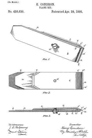
Figure 1 is a perspective view of a plane-bit embodying the features of my invention. Fig. 2 is a front view of the same, and Fig. 3 is a central longitudinal sectional view thereof.
Like letters of reference in the different figures indicate like parts.
My invention relates to that class of plane-bits in which the chisel or cutting portion is made from a thin plate of steel supported by a back plate of inferior metal. This construction, while possessing many advantages, is subject to the objection that a considerable vibration thereof is produced in planing hard woods, which makes it impossible to produce satisfactory work with it.
The object of my invention is to overcome this objection by providing a supplemental clamp-plate, by which the thin chisel-plate is supported at the point of greatest strain, while the usual clamp-plate is retained to regulate the “bite” of the chisel; all of which is hereinafter more particularly described, and definitely pointed out in the claims.
Referring to the drawings, a represents the plane-chisel, which consists of a thin plate of steel, having the usual chisel-edge a’, Fig. 3.
b is the back plate, and c the usual front or clamping plate bent, as shown at c’, and having the usual thin tapered edge c2, as shown, which is intended to be adjusted near to the chisel-edge a’, according to the work to be done, said tapered edge of the clamping-plate being preferably below the end b’ of the back plate b.
The chisel, back plate, and clamp-plate are attached to each other by means of the usual clamp-screw d. It will be seen that a pressure upon the point a’ of the chisel tends to bend said chisel back over the edge b’ of the back plate, which forms a fulcrum therefor. To overcome this tendency, I interpose a supplemental clamp-plate e between the chisel a and clamp-plate c, which supplemental plate is bent at e’, and the edge of which bears upon the chisel-plate above the edge b’ of the back plate b and at the point of greatest vibration in said chisel-plate. It is obvious that upon clamping the respective plates together, as shown, by means of the clamp-screw, the pressure upon the chisel-plate a is as great above as below the lower end of the back plate. I have found in actual practice that all vibration of the chisel is thereby obviated.
Having thus described my invention, what I claim, and desire to secure by Letters Patent, is —
1. The combination, in a plane-bit, of a chisel consisting of a thin plate of steel, a back plate, a clamp-plate having its edge below the edge of the back plate, and an interposed supplemental clamp-plate having its bearing edge upon the plane-chisel above the lower edge of the back plate, substantially as shown and described.
2. The combination, in a plane-bit, of the chisel a, back plate b, clamp-plate c, supplemental clamp-plate e, and a clamp-screw for holding the same in the respective positions with relation to each other, substantially as shown and described.
In testimony whereof I have signed this specification, in the presence of two subscribing witnesses, this 6th day of February, 1890.
HENRY CONDRON.
Witnesses:
D. H. FLETCHER,
J. B. HALPENNY.