No. 398,247 – Plane (Henry Fry) (1889)

UNITED STATES PATENT OFFICE.
_________________
HENRY FRY, OF EUGENE CITY, OREGON.
PLANE.
_________________
SPECIFICATION forming part of Letters Patent No. 398,247, dated February 19, 1889.
Application filed September 13, 1888. Serial No. 285,311. (No model.)
_________________
To all whom it may concern:
Be it known that I, HENRY FRY, a citizen of the United States of America, residing at Eugene City, in the county of Lane and State of Oregon, have invented certain new and useful Improvements in Planes; and I do hereby declare the following to be a full, clear, and exact description of the invention, such as will enable others skilled in the art to which it appertains to make and use the same, reference being had to the accompanying drawings, and to letters or figures of reference marked thereon, which form a part of this specification.
My invention relates to improvements in carpenters’ planes; and it consists in the novel construction and combination of the parts thereof, as will be more fully hereinafter described and claimed.
The object of my invention is to construct a plane wherein the depth of cut of the bit may be adjusted while the plane is in motion without readjusting the bit after the initial setting thereof. I attain this object by the construction illustrated in the accompanying drawings, wherein like letters of reference are used to designate similar parts in the several views, and in which —
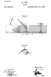
Figure 1 is a sectional elevation of a plane, showing my improved construction in connection therewith. Fig. 2 is a detail perspective view of the bit-guard.
S indicates the stock, having the handle s, bit aperture or well s’, and bit and wedge W, all of which are well known in the art.
The improvement consists in securely hinging to the back end of the stock S a movable shoe or bottom, B. To the forward part of the shoe B a stationary flanged socket-nut, E, is secured, the screw-threaded socket thereof projecting upward into and movable in a recess formed in the stock S. An elongated rod, A, having a lower screw-threaded end to engage the screw-threaded socket of nut E and a top projecting knob for engagement by the operator passes through an aperture in the plane-stock. The said rod A immediately under the top knob is provided with a collar, a; and over this collar and fitted into the top surface of the stock is a plate or plates for holding the said collar and screw-rod down and preventing the same rising from the stock.
To prevent the bit from springing backward when striking knots or when cutting deep in hard wood, due to its extended projection from the bottom of the stock to accommodate the improved construction, I provide a guard-casting, F, which is secured to the bottom of the stock adjacent to the bit-end. This guard consists of a horizontal plate, f having screw-holes therein, and an obliquely-arranged plate, f’, integrally formed with its forward end. The oblique plate f’ has its lower edge beveled, and the greater part thereof projects below plate f. When this guard is adjusted in position, the plate f’ thereof bears against the lower end of the bit and prevents the same from springing backward. The part of plate f’ above plate f sinks into the wood or metal of the stock and firmly re-enforces the guard at this point.
The shoe B, working on the hinge and adjusted by the screw-rod A, virtually raises and lowers the plane-bit from and toward the surface planed, causing it to out a light or heavy shaving at the will of the operator, and the adjustment set forth may be readily attained while the plane is in motion, thereby saving the time and labor involved in setting the bits of planes now in use.
In using an iron plane-stock with a wooden shoe, B, two bosses or lugs cast with the back end of the stock would make the hinging of said shoe practicable, and the screw-rod A would then work through the iron stock.
Having thus described my invention, I claim —
1. In a plane,the combination, with a stock having a bit-well therein, of an elongated shoe hinged thereto and solid throughout with the exception of a slot therein for the passage of the bit therethrough, a screw-rod for adjusting said shoe, and a casting composed of a horizontal member secured to the bottom of the stock adjacent to the bit-well, and a front integral member arranged at an angle to said horizontal member, and against which the bit has bearing at its lower end, substantially as described.
2. A plane comprising a, stock with at bit-well, an elongated shoe hinged to the rear end of the stock and having a flanged set-nut secured therein near the front end, a revoluble screw-rod in the stock engaging the set-nut, and a casting, F, having a horizontal member, f, secured to the bottom of the stock, and integral oblique member f’, bearing against the lower end of the bit, substantially as described.
In testimony whereof I aflix my signature in presence of two witnesses.
HENRY FRY.
Witnesses:
W. R. McCORMACK,
JOEL WARE.


