No. 744,411 – Spokeshave (Huldege Sarasin) (1903)

UNITED STATES PATENT OFFICE.
_________________
HULDEGE SARASIN, OF AMESBURY, MASSACHUSETTS.
SPOKESHAVE.
_________________
SPECIFICATION forming part of Letters Patent No. 744,411, dated November 17, 1903.
Application filed December 4, 1902. Serial No. 133,829. (No model.)
_________________
To all whom it may concern:
Be it known that l, HULDEGE SARISIN, of Amesbury, county of Essex, State of Massachusetts, have invented an Improvement in Spokeshaves, of which the following description, in connection with the accompanying drawings, is a specification, like characters on the drawings representing like parts.
This invention relates to spokeshaves, and more particularly to spokeshaves which are especially adapted for use in finishing the bodies of carriages.
In the manufacture of carriage-bodies the panels are often rounded at their edges, and in order that this may be readily accomplished I have found it desirable to set the blade of the spokeshave which is used in rounding these edges obliquely with respect to the face of the shave, so that a wedge-shaped shaving will be removed by the blade, thereby enabling the rounding of the panels to be accomplished much more readily than if the blade were set parallel with the face.
The object of my invention is to provide an adjusting means for the blade of a spoke-shave which will enable the blade to be readily adjusted to exactly the desired position with respect to the face of the shave and then to firmly clamp the same while it is held in this position.
For an understanding of the means which I employ to accomplish this object reference is now made to the accompanying drawings, in which —
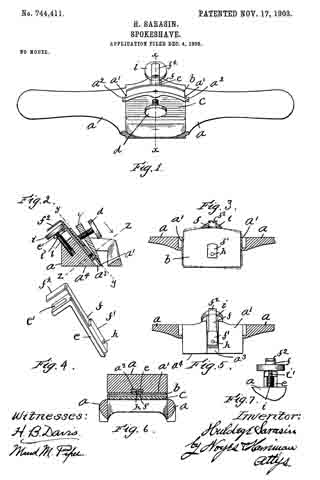
Figure 1 is a plan view of a spokeshave made according to my invention. Fig. 2 is a cross-section thereof on the line x x of Fig. 1. Fig. 3 is a section on the line y y of Fig. 2. Fig. 4 is a detail view in perspective of the adjusting means for the blade. Fig. 5 is a view similar to Fig. 3 with the blade removed. Fig. 6 is a cross-section on the line z z of Fig. 2. Fig. 7 is a detail view showing the connection between the adjusting screw and slide.
The main body or holder a of the shave is of usual form, having a seat a’, on which a blade b rests, said blade fitted between shoulders at each side of the seat. A clamping-wedge c is adapted to loosely engage grooves a2 in said shoulders, and a clamping-screw d is threaded in said clamping-wedge c and is adapted to engage the upper side of the blade, pressing the under side thereof firmly against the seat a’ and pressing the lower end of the clamping-wedge c against the upper side of the blade. The seat a’, against which the blade is pressed, is provided with a transversely-extending groove a3 in the middle thereof, which extends from the work-face a4 of the holder to the opposite side of said seat.
An adjusting-slide e is fitted to slide in said groove as and is bent at right angles at its upper end and has a slot e’ formed therein. An adjusting-screw i is threaded in the holder in the rear of said slide and is provided with a grooved portion i’, which is fitted in said slot e’ of the slide, so that a swivel connection between said screw and slide is provided. An arm or lever f is pivoted at h to the upper side of said slide and is provided with an angular-shaped projection f’, which is adapted to fit tightly in a correspondingly-shaped aperture in the middle of the blade b, said projection being arranged near the lower end of said lever. The particular shape of this projection is not essential, as any similar form of connection which will prevent the blade from swinging on the lever, yet which will enable the blade to be readily removed, will answer the purpose. A handle f2 extends at an angle to said lever over the head of the adjusting-screw i. The combined thickness of the slide e and lever f is no greater than the depth of the slot a8, the projection f’ being the only part of this adjusting means which extends above the face of the seat a’.
The manner of securing the blade to the holder and of adjusting the same is as follows: The slide e is placed in the groove a3, and the grooved portion of the adjusting-screw i is placed in the slot e’, as shown in Figs. 2 and 7. The blade is then placed on the pivoted arm of lever f, so that the projection f’ thereof fits into the aperture through the blade, and the clamping-wedge c and screw d are placed in position and the screw is tightened, so that they press gently against the blade. Then the screw i is adjusted back and forth until the cutting edge of the blade protrudes the desired distance below the face of the shave, and the lever f is then swung in either direction, swinging the blade, so that its cutting edge is either in an oblique position with respect to the face of the holder, as indicated in dotted lines, Fig. 3, or is exactly parallel therewith, as shown in full lines. The screw d is then tightened, clamping the blade in the position to which it was adjusted. If it is desired to change the adjustment of the blade, it is simply necessary to loosen the screw d and swing the lever f or draw the slide e up or down by means of the screw i until the desired adjustment has been secured.
Having thus described my invention, what I claim as new, and desire to secure by Letters Patent, is —
1. In a spokeshave, a holder having a work-face and a blade-seat, a blade resting on said seat, and means for clamping the same thereon, a slide and means for adjusting the same to and from the work-face, and for holding the same against transverse movement, an adjusting-lever pivoted to said slide, engaging means between said blade and lever for holding the blade from swinging movement with relation to the lever, whereby said lever and blade may be simultaneously swung on the same pivot, substantially as described.
2. In a spokeshave, a holder having a work-face, and a blade-seat, a blade resting on said seat and means for clamping the same thereon, a slide and means for adjusting the same to and from the work-face, and for holding the same against transverse movement, an adjusting-lever pivoted to said slide, a projection rigid with said lever and arranged in a correspondingly-shaped aperture with which said blade is provided, and holding the blade from swinging movement with relation to the lever, whereby said blade and lever may be simultaneously swung on the same pivot, substantially as described.
In testimony whereof I have signed my name to this specification in the presence of two subscribing witnesses.
HULDEGE SARASIN.
Witnesses:
LOUIS H. HARRIMAN,
H. B. DAVIS.


