No. 417,144 – Spokeshave (Isaac Camier) (1889)
UNITED STATES PATENT OFFICE.
_________________
ISAAC CAMIER, OF CHICAGO, ILLINOIS.
SPOKESHAVE.
_________________
SPECIFICATION forming part of Letters Patent No. 417,144, dated December 10, 1889.
Application filed March 23, 1889. Serial No. 304,516. (No model.)
_________________
To all whom it may concern:
Be it known that I, ISAAC CAMIER, a citizen of the United States, residing at Chicago, in the county of Cook and State of Illinois, have invented certain new and useful Improvements in Spokeshaves; and I do hereby declare the following to be a full, clear, and exact description of the invention, such as will enable others skilled in the art to which it appertains to make and use the same.
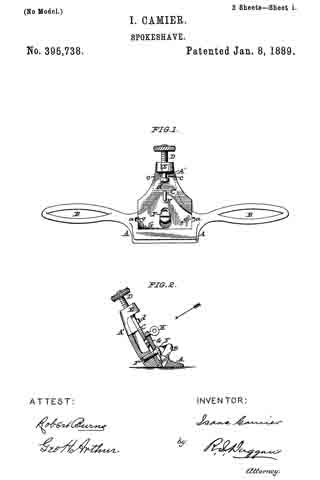
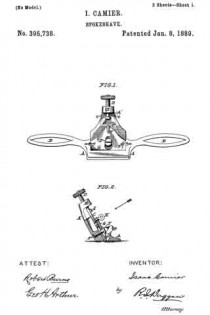
This invention relates to certain improvements in the type of spokeshaves shown and described in Letters Patent No. 395,738, issued me January 8, 1889; and the present improvements have for their objects, first, to provide an improved construction which, while furnishing ample and effective means for clamping and holding the cutter-bit, will admit of the use of almost the whole of the same to accommodate for wear due to constant resharpening; second, to afford a simple and effective means for adjusting the cutter-bit to its proper cutting position; third, to provide an efficient and ready means whereby the working-face of the “shave” can be adjusted to suit any desired curvature, either concave or convex; fourth, to provide means for effecting a lateral adjustment of the cutter-bit within the throat of the shave, so as to effect a uniform projection of the cutting-point with relation to the face of the shave; fifth, to afford a simple, cheap, and effective construction for attaching in a non-rotary condition the adjusting-screw to the top of the cutter-bit. I attain such objects by the construction and arrangement of parts illustrated in the accompanying drawings, in which —
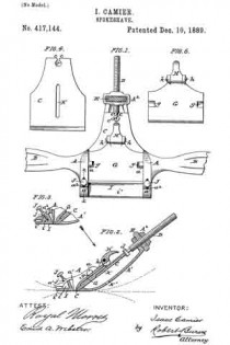
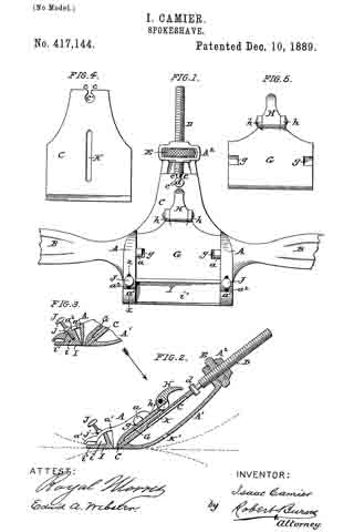
Figure 1 is an elevation, in the direction of the arrow shown in Fig. 2, of a spokeshave constructed in accordance with my invention; Fig. 2, a transverse axial section of the same; Fig. 3, a detail section at line x x, Fig. 1; Fig. 4, an elevation of the back of the cutter-bit; Fig. 5, an elevation of the clamping-plate.
Similar letters of reference indicate like parts in the several views.
The body or stock A of the shave is provided with the usual side wings B, by which the spokeshave is grasped and manipulated by the operator. The cutter-bit C, as in my former patent above referred to, will lit snugly within the throat of the stock A, so as to be guided thereby in its adjustment, and its upper end will be formed with inturned lips c, that form an attaching-recess to receive the headed end d of the screw D, by which the adjustment of the cutter-bit is effected.
In the present improvement the head d of the screw D is formed by a cylindrical transversely-extending shank or end d, over which engages the circular part of the notch c’ in the upper end of the cutter-bit, the contracted portion of said notch, that extends to the upper end of the bit, being made flaring, so as to admit of a lateral adjustment of the cutter-bit with the rounded shank d as a fulcrum-point for such adjustment, as hereinafter more fully set forth. By this means a very cheap and effective attachment of the parts is effected.
As distinguished from my former patent, the present construction of the adjusting-screw consists as follows: The upper end of the inclined back standard A’ of the shave-stock A is formed with a laterally or transversely slotted head A2, within the slot of which is arranged the adjusting thumb-nut E of the screw D in such a manner as to be capable of free rotary movement without any capability of a movement in line with the axis of its screw D, so that as it is rotated by the thumb and finger of the operator it will raise or lower the screw D and with it cutter-bit C in accordance with the direction in which it is rotated.
In the present improvement the clamping-plate G, by which the cutter-bit C is firmly clamped at its required adjustment, is held in place within the throat of the stock in a pivotal manner by being slipped under the overhanging inwardly-projecting lugs a at the sides of the throat of the stock A, recesses g being formed in the top edges of the clamping-plate to partly receive such lugs, so that the plate will be held from any other than a pivotal movement.
The usual clamping-screw may be used at the top of the plate G to effect the pivotal movement of such plate so as to clamp or release the cutter-bit, as set forth in my former patent. However, I prefer the following improved construction.
h h are a pair of counterpart lugs or ears centrally arranged at the upper end of the clamping-plate G, between which is pivoted the lever-cam H, the cam portion of which is adapted to bear upon the cutter-bit. so that when turned it will pivotally move the clamping-plate G to either clamp or release said cutter-bit.
The cam portion of the lever-cam will be made of some width so that it can be centrally cut away, as indicated in Fig. 2, so as to admit of the passage downward of the head d of the adjusting-screw in the downward adjustment of the cutter-bit.
The toe or forward bearing part I of the stock A, I make circular, adjustable on a center closely adjacent to the cutting-point of the bit C, so that it can be adjusted to suit any variety of work-either straight, convex, or concave — as indicated in dotted lines on the drawings.
My preferred manner of accomplishing such adjustment is by forming such toe with sector-shaped ends i, preferably formed with a straight-forward extension i’, and arranging the same to slide beneath the curved hoods a’ at each forward end of the stock A.
The parts are clamped and held to their required adjustment by means of a set-screw J at each end, which passes through an elongated slot a2 in each hood and screws into the sector-shaped ends i, as shown, j being a bearing-collar on each wider than the slots a2 and adapted to bear upon the outer surface of the hoods, as clearly represented in Figs. 1 and 2.
To effect a lateral adjustment of the cutter-bit within the throat of the shave, so that the cutting-edge will be brought on a line parallel with the face of the shave, I provide the following improved construction:
K is a slot or groove extending centrally up the back of the cutter-bit; K’, a hole or perforation in the back of the stock A, which forms a fulcrum for the bar or other instrument, that is put through such hole or opening to engage in the groove or slot K to effect the lateral adjustment of the cutter-bit.
Having thus fully described my said invention, what I claim as new, and desire to secure by Letters Patent, is —
1. The combination, in a spokeshave, of the stock A, having curved hoods a’ at its forward edge, the adjustable toe or forward part formed with sector-shaped ends i, and the clamping-screws J, passing through elongated slots a2 and screwing into the sector-shaped ends i, substantially as herein described.
2. The combination, in a spokeshave, of the adjusting-screw D, provided with a cylindrical transversely-extending shank d, and the cutter-bit C, provided with the circular openended hole or perforation c’, essentially as and for the purpose set forth.
3. The combination, in a spokeshave, of the cutter-bit C, provided with the groove or slot K, extending centrally up the back of the same, and the stock A, provided with a perforation K’ in line with the slot or groove K, essentially as and for the purpose set forth.
In testimony whereof I affix my signature in presence of two witnesses.
ISAAC CAMIER.
Witnesses:
ROYAL MORRIS,
ROBERT BURNS.

