No. 1,354,651 – Extension Attachment For Carpenters’ Planes (Iver James) (1920)

UNITED STATES PATENT OFFICE.
_________________
IVER JAMES, OF SEATTLE, WASHINGTON.
EXTENSION ATTACHMENT FOR CARPENTERS’ PLANES.
_________________
SPECIFICATION of Letters Patent No. 1,354,651, dated December 18, 1855.
Application filed December 18, 1880. (No model.)
1,354,651. Specification of Letters Patent. Patented Oct. 5, 1920.
Application filed November 24, 1919. Serial No. 340,107.
_________________
To all whom it may concern:
Be it known that I, IVER JAMES, a citizen of the United States, residing at Seattle, in the county of King and State of Washington, have invented a certain new and useful Improvement in Extension Attachments for Carpenters’ Planes, of which the following is a specification.
My invention relates to improvements in attachments for carpenters’ planes of the type commonly used for planing lumber, and the object of my improvement is to provide a strong, simple, and relatively cheap attachment by which a plane of short length as an ordinary jack plane or smoothing plane can be quicldy and easily converted into a longer plane as a jointer, without any substantial alteration of the shorter plane.
A further object is to provide novel, efficient and quickly releasable means for rigidly securing the attachment to the shorter plane.
The invention consists in the novel construction of an attachment for a carpenter’s plane and in the novel construction, adaptation and combination of parts by which such attachment is secured to a plane as will be more clearly hereinafter described and claimed.
Certain classes of carpentry work require the use of a short plane, while other classes of work require the use of longer planes, thus making it necessary for the carpenter doing ordinary work to provide himself with two or more separate planes that are substantially identical, except as to the length of the base or body portion of the plane. The present invention contemplates the use of an extension in the form of a separable base or body portion, by which a shorter plane may be converted into a longer plane.
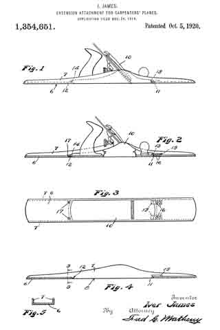
In the accompanying drawings Figure 1 is a view in side elevation of an extension constructed in accordance with my invention as it may appear when it has a plane installed therein; Fig. 2 is a view in longitudinal section of the same, parts of the plane being shown in elevation; Fig. 3 is a plan view of the bottom of the plane and extension that are shown in Figs. 1 and 2; Fig. 4 is a detached view in longitudinal section of the extension and Fig. 5 is a view in cross section on broken lines 5, 5 of Fig. 4.
Like reference numerals designate like parts throughout the several views.
The extension comprises a relatively long, channel shaped member, having a flat straight bottom wall 6 that is provided with upwardly projecting integral side flanges or side walls 7 that are preferably of greater width at the center and taper toward the ends of the extension in substantially the same manner as the sides of the body portion of an ordinary plane.
The central portion of the bottom wall 6 is cut away as at 8 to leave an opening of the same width and of slightly shorter length than the bottom of a jack plane or smoothing plane 10 on which the attachment is to be used and the bottom 6 at the front and rear ends of the opening 8 is beveled as at 11 and 12 respectively to fit the correspondingly beveled ends 13 and 14 of the plane 10.
The devices for engaging with and holding the front end of the plane 10 comprise two metal strips or dogs 15 that are permanently secured to the bottom 6 by rivets 16 and overhang the beveled portion 11 so that the front end of the plane 10 may be inserted thereunder as shown in Fig. 2.
The rear end of the plane 10 is rigidly secured to the bottom 6 of the extension member by screws 17 that screw into the bottom 6 and whose heads overlap and engage with the beveled end 14 of the plane.
The beveled ends 13 and 14 are the only alterations that are made on the plane 10 and these alterations do not interfere with the use of such plane as a jack plane or smoothing plane when the extension is removed.
When the plane 10 is secured in the attachment the bottom of the plane is exactly flush with the bottom of the attachment so that the device will function in the same manner as a jointer plane.
The sides of the attachment are spaced just far enough apart so that the plane 10 will fit snugly therebetween and the dogs or strips, 15 and screws 17 serve to fixedly secure the plane and the attachment together so that there is no relative movement therebetween.
The attachment is not heavy or cumbersome when carried in a tool chest, is not expensive to manufacture, is strong in construction, is ea.sy to attach to and detach from a plane and may be readily used for converting a shorter plane into a longer one, thereby enabling a carpenter to dispense with one of the tools that is required in ordinary work.
While the device is described as being particularly well adapted for converting a jack plane or smoothing plane into a jointer piane, it will be understood that it may be used for converting any short plane into a longer one.
Obviously changes in the form, dimensions and arrangement of parts of this device may be resorted to within the scope of the following claims.
What I claim is:
1. An extension for a carpenter’s plane comprising a relatively long, straight, fiat bottomed member of channel shaped cross section having the central portion of its bottom cut away to permit the insertion of a carpenter’s plane, the said bottom being beveled at the ends of said cut away portion to fit correspondingly beveled ends on said plane and means for securing said extension to the ends of said plane.
2. The combination with a relatively short carpenter’s plane that has its ends beveled from the bottom upwardly of a relatively long, straight, flat bottorned extension member of channel shaped cross section and having its central bottom portion cut away and having the said bottom beveled at the ends of said cut away portion to fit the beveled ends of said plane, dogs rigidly secured to said extension member and overhanging one of said beveled portions and screws. in said extension at the other of said beveled portions, the said dogs and the said screws serving to secure said extension to said plane.
Signed at Seattle, Washington, this 12th day of November 1919.
IVER JAMES.


