No. 381,186 – Plane (Reinhard T. Torkelson And Iver Johnson) (1888)
UNITED STATES PATENT OFFICE.
_________________
REINHARD T. TORKELSON AND IVER JOHNSON, OF WORCESTER, MASSACHUSETTS.
PLANE.
_________________
SPECIFICATION forming part of Letters Patent No. 381,186, dated April 17, 1888.
Application filed September 14, 1885. Serial No. 177,099. (No model.)
_________________
To all whom it may concern:
Be it known that we, REINHARD T. TORKELSON and IVER JOHNSON, both of the city and county of Worcester, and Commonwealth of Massachusetts, have invented certain new and useful Improvements in Planes; and we do hereby declare that the following is a full, clear, and exact description of the same, reference being had to the accompanying drawings, forming a part of this specification, in which —
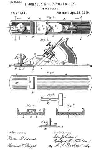
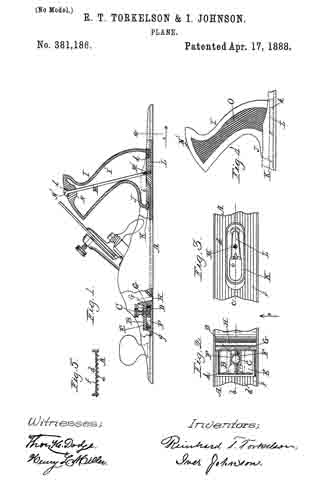
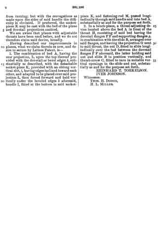
Figure 1 represents a vertical section through the ends of the plane on line b c, Figs. 2 and 3; Fig. 2, a top or plan view of the front of the plane; Fig. 3, a top or plan view of the rear section of the plane with the handle removed; Fig. 4, a side view of the handle and a small section of the plane-bed; and Fig. 5 represents a cross-section on line a, Fig. 1, looking in the direction of arrow 1.
To enable those skilled in the art to which our invention belongs to make and use the same, we will proceed to describe it more in detail, the nature of which consists, first, in certain improvements in the construction of an adjustable throat device; second, in improvements in the construction, whereby the handle may be detachably fastened to the bed; and, third, in an improved plane-bed, all as will be hereinafter more fully described.
In the drawings, A represents the bed of the plane,which is provided with corrugations d, the lower edges, e, of which are flat, and upon its upper side with round corrugations f. By this construction of the bed it can be made very light, while at the same time it is very stiff, thus utilizing in material, while at the same time rendering it light, and thus requiring less labor to operate it.
B represents an adjustable throat arranged upon the upper side of the plane-bed, through which a thumb-screw, C, passes into a set-nut, D. This nut works between two dovetail flanges, F F, (shown in full lines, Fig. 1, and dotted lines, Fig. 2,) the sides of the nut being made dovetailing to fit, and, consequently, while the nut can be moved back and forth it cannot be raised out of place until screw C and throat B are removed.
The body part E of the adjustable throat rests upon upright flanges g, (shown in full lines, Fig. 1, and dotted lines, Fig. 2,) and between the side flanges ofthe plane-bed F F. A forward projection, G, fits into the throat H, and which projection can be slid back and forth, as indicated in full and dotted lines, Fig. 1, and quickly adjusted, by means of the thumb-screw G, to give any desired opening to the throat H. This arrangement also leaves the under side of the bed of the plane smooth, thereby obviating the objections to the adjustable throats heretofore fitted to work on the under side of the plane.
I represents the handle of the plane, made of vulcanized india-rubber. It is made hollow, as seen at I’, and with a rounded base, J, to fit into a socket-piece, K, which in turn is made with an oblong slot, i, having edges inclined toward each other, so that said socket-piece K may be placed over the dovetail projection L on bed A, and when forced forward into the position shown in Fig. 1 it is securely held in said position vertically under the beveled edges k of said projection L. The base of handle I is now placed in the socket-piece K, and the screw-rod M passed down through the top and screwed into hole M’ in the dovetail projection L, thereby securing the handle firmly in position, while at the same time admitting of the detachment of said handle in an easy and expeditious manner. A forward projection, N, is cast upon the under side of the top of the handle, as fully indicated in Fig. 1, and a metal socket-piece, Z, is ntted into the top of handle I, to receive and hold the head N’ of the screw-rod M. The sides of the handle are made with a series of notches or corrugations, O, whereby when the handle is clasped in the hand the soft skin and flesh of the fingers will be pressed into the corrugations and notches on one side of the handle, while the skin and soft flesh of the hand at the base of the fingers will be pressed into the corrugations upon the opposite side of the handle. By this arrangement the operator can handle the plane much easier and with less exertion, particularly when he is obliged to hold up the plane to plane the edge of a piece of board, which is frequently required in the usual work of a carpenter. If the handle were smooth, a little perspiration or oil would require a great strain upon the fingers and cords of the hand to hold the plane from turning; but with the corrugations as made upon the sides of said handle the difficulty is obviated. If preferred, the socket-piece K may be cast with the bed of the plane and dovetail projections omitted.
We are aware that planes with adjustable throats have been used before, and we do not therefore claim said device, broadly.
Having described our improvements in planes, what we claim therein as new, and desire to secure by Letters Patent, is —
1. The combination of bed A, having the rear projection, L, upon the top thereof provided with the dovetail or bevel edges k, substantially as described, with the detachable socket-piece K, provided with an oblong vertical slot, i, having edges inclined toward each other, and adapted to be placed over said projection L, then forced forward and held vertically under the beveled edges k aforesaid, handle I, fitted at the bottom in said socket-piece K, and fastening-rod M, passed longitudinally through said handle and into bed A, substantially as and for the purpose set forth.
2. In a bench-plane, a throat-adjusting device located above the bed A in front of the throat H, consisting of said bed having the dovetail flanges F F and supporting-flanges g, in combination with the slide B, arranged over said flanges, and having the projection G next to said throat, the nut D, fitted to slide longitudinally over the bed between the dovetail flanges F F aforesaid, the latter holding said nut and slide B in position vertically, and thumb-screw C, fitted to turn in suitable vertical openings in the slide and nut, substantially as and for the purpose set forth.
REINHARD T. TORKELSON.
IVER JOHNSON.
Witnesses:
THOS. H. DODGE,
H. L. MILLER.