
No. 16,569 – Joiner’s Plane (J.F. Palmer) (1857)
UNITED STATES PATENT OFFICE.
_________________
J. F. PALMER, OF AUBURN, NEW YORK, ASSIGNOR TO S. W. PALMER, OF DETROIT, MICHIGAN.
JOINER’S PLANE.
_________________
Specification of Letters Patent No. 16,569, dated February 3, 1857.
_________________
To all whom it may concern:
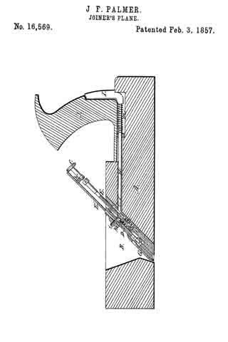
Be it known that I, J. F. PALMER, of Auburn, in the county of Cayuga and State of New York, have invented a. new and useful Improvement in Joiners’ Planes; and I do hereby declare that the following is a full, clear, and exact description of the same, reference being had to the annexed drawing, making a part of this specification, said drawing being a longitudinal vertical section of my improvement.
My invention consists in the peculiar means employed for adjusting the plane iron, as will be hereinafter fully shown and described, whereby the plane iron may be set with the greatest facility and also be raised free from the work as the plane is drawn back so that the cutting edge of the iron is not impaired thereby.
To enable those skilled in the art to fully understand and construct my invention, I will proceed to describe it.
A represents the plane stock which is constructed of wood and in the usual manner. B is the opening or throat in the plane, and C is a metal plate which is screwed to the back side of the opening or throat, the lower edge of the said plate being beveled and made flush with the bottom or face of the stock. The upper end of the plate is also flush with the upper surface of the stock. The plate C has an oblong recess (a) made in it to receive a spiral spring (b) and also has four guide slots made in it to receive pins (d) which are attached to the back of a plate D which is fitted over the plate C, the plate D being a trifle shorter than the plate C. The plate D has a projection or lip (e) on its back side, said projection or lip fitting over the spring (b) in the recess (a) of the plate C. The projection or lip (e) is notched, or it may be formed of two parts to allow a screw rod E to pass through it. The upper end of the screw rod has a small thumb wheel (f) upon it, and a groove or recess (g) is made circumferentially in the upper part of said rod to receive a fork (h) which is attached to the back side of the plane iron E’. The lower part of the screw rod has a nut F upon it which leans upon the projection or lip (e) on the plate D, and this nut has a screw (i)attached to it, said screw passing through a hole (j) in the plate D, and through a slot (j’) in the plane iron E’, and having a thumb nut (k) on its outer end. The lower part of the plane iron E’ has a cover iron G attached to it.
The upper edge of the nut F is beveled as plainly shown in the drawing, and a rod H is fitted longitudinally in the stock A, said rod having a vertical plate I attached to its back end, the plate I being at the back side of the tote or handle J. The front end of the rod H has a fork (l) formed on it, and when the rod H is pressed forward, it passes through an opening in the plate C and bears upon the upper nut F — a spiral spring (m) is placed upon the rod H, said spring keeping the fork free from the nut F.
From the above description will be seen that by turning the screw rod E, the plane iron E’ may be raised or lowered so as to give it the required “set,” and the plane iron is firmly secured in position or prevented from turning casually. The plate D is connected with the plate C by a guide pin so as to regulate the length of vibration of the plate D and plane iron E’, which are forced downward as the plane is shoved forward by pressing the palm of the hand against the plate I, the rod H being shoved forward thereby and the fork (l) bearing or pressing down the nut F, and consequently the plate D and plane iron E’, said plate and plane iron being kept up above the work or board being planed by means of the spring (b).
By the above improvement the plane iron may not only be set with facility but it is kept up from the work as the plane is drawn backward and consequently the cutting edge of the iron E’ is prevented from being rounded and rendered dull. The plane irons of ordinary planes are soon deprived of their sharp edges in consequence of being drawn backward over the work.
Having thus described my invention, what I claim as new and desire to secure by Letters Patent, is,
The two plates C, D, and plane iron E’ arranged relatively with each other as shown and used in connection with the screw rod E, and rod H as herein described and for purpose set forth.
J. F. PALMER.
Witnesses:
HORACE T. COOK,
C. H. JENKIN.