No. 538,937 – Combination-Plane (Jacob W. Tripp) (1895)

UNITED STATES PATENT OFFICE.
_________________
JACOB W. TRIPP, OF SALT LAKE CITY, UTAH TERRITORY.
COMBINATION-PLANE.
_________________
SPECIFICATION forming part of Letters Patent No. 538,937, dated May 7, 1895.
Application filed August 9, 1894. Serial No. 519,912. (No model.)
_________________
To all whom it may concern:
Be it known that I, JACOB W. TRIPP, of Salt Lake City, in the county of Salt Lake and Territory of Utah, have invented a new and Improved Combination-Plane, of which the following is a full, clear, and exact description.
The object of the invention is to provide a new and improved plane, which is comparatively simple and durable in construction, arranged for universal adjustment to enable the operator to conveniently plane straight or curved work, such as stair rails, on all sides, and for molding, fitting, plowing, tonguing and grooving, rabbeting and other purposes, also to form beads, fillets, &c.
The invention consists principally of a stock adapted to receive a removable wooden sole piece shaped to conform to the curved or straight surface to be planed.
The invention further consists in a bit having gear teeth adapted to be engaged by a segmental lever, for shifting the said bit into proper position.
The invention also consists in an auxiliary guide stock pivoted on an adjustable arm held on the main stock.
The invention also consists in certain parts and details, and combinations of the same, as will be fully described hereinafter, and then pointed out in the claims.
Reference is to be had to the accompanying drawings, forming a part of this specification, in which similar letters of reference indicate corresponding parts in all the views.
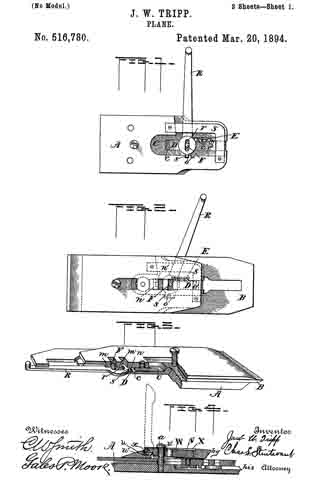
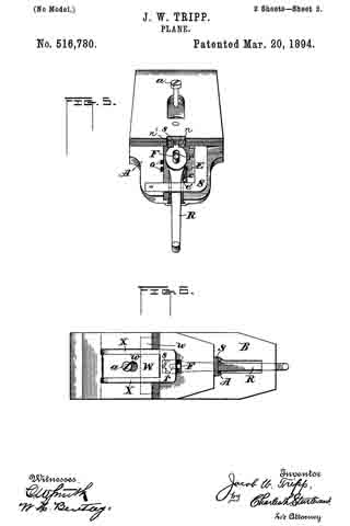
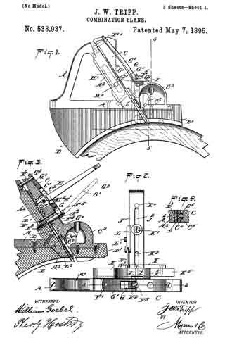
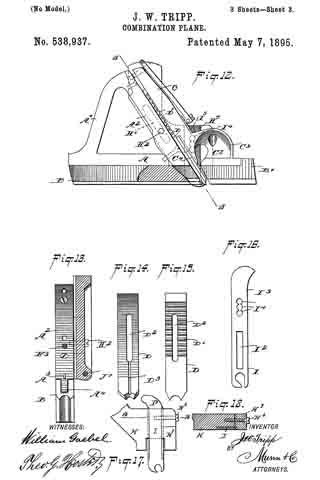
Figure 1 is a side elevation of the improvement. Fig. 2 is a plan view of the same. Fig. 3 is a sectional side elevation of the improvement on the line 3 3 of Fig. 2. Fig. 4 is an enlarged transverse section of the bit-guide, the section being taken on the line 4 4 of Fig. 3. Fig. 5 is a transverse section of the improvement on the line 5 5 of Fig. 1. Fig. 6 is a sectional rear elevation of part of the improvement on the line 6 6 of Fig. 5. Fig. 7 is a side elevation of the improvement, showing a modified form of sole-piece. Fig. 8 is a perspective view of a modified form of guide-piece for the auxiliary guide-stock. Fig. 9 is a perspective view of a modified form of sole-piece in front of the cutting-bit. Fig. 10 is a sectional plan view of part of the improvement on the line 10 10 of Fig. 7. Fig. 11 is a rear elevation of the auxiliary guide and adjacent parts. Fig. 12 is a side elevation of the improvement arranged with a straight wooden sole-piece, part of which is broken out. Fig. 13 is a sectional plan view of the same on the line 13 13 of Fig. 12. Fig. 14 is an inverted plan view of the bit. Fig. 15 is a plan view of the same. Fig. 16 is a face view of a combination quick cutter and blank. Fig. 17 is a face view of a modified form of fastening for the quick cutter, and Fig. 18 is a sectional plan view of the same on the line 18 18 of Fig. 17.
The improved plane is provided with the metallic stock A, having an integral handle A’, and a bit plate A2 extending in an inclined direction, as plainly shown in Figs. 1 and 3, and fastened by screws or other means to the stock A and handle A’. On the under side of the stock A, is adapted to be secured by screws orother means, a sole piece B, having its bottom made in various shapes according to the article to be planed. The sole piece is made of wood, and is shaped at its under side to correspond to the shape of the article to be planed, as will be readily understood by reference to Fig. 1, or is made straight at its under side for planing straight surfaces of different shapes, as illustrated in Fig. 12.
On the lower end of the cap C is secured a sole piece B’, forming a continuation of the sole piece B, and shaped according to the article under treatment, that is, either curved at the under side, as shown in Fig. 1, or straight as illustrated in Figs. 9 and 12. The pressure plate or cap C for the plane, is adapted to engage and hold the cutting bit D on the bit plate A2.
In order to shift the bit D, I form the top surface thereof at the upper end with rack teeth D’ adapted to be engaged by the teeth E’ of a segmental lever E, formed with a slot E2 adapted to engage a pin C’ extending transversely in the pressure plate C, and through an aperture C2 therein, as will be readily understood by reference to Fig. 3. Now when the pressure plate C is in place, the operator inserts the segmental lever E in the aperture C2, so that the pin C’ forms a fulcrum for the said lever, and the teeth E’ of the latter engage the rack teeth D’ of the bit D. When the operator swings the lever E either up or down, then the teeth E’ shift the bit D down or up, so as to adjust the cutting edge of the bit according to the under side of the sole piece B. After proper adjustment is made of the bit D, then the segmental lever E is again removed from the aperture C2 and the pin C’. The pressure plate or cap C is held from sliding by dowels F, F’, which project at right angles from the bit plate A2. See Fig. 3. To clamp the bit in place on the bit plate A2, I provide a screw rod F2, secured in the bit plate A2, parallel to the dowels F F’. The screw rod F2 is provided with the smooth piece F3, extending through the bit slot D2 and the cap C. The reduced end F4 of the screw rod F2 engages a removable block G, fitting under the head F5 of the said screw rod, and on the sides of the said block G is fulcrumed a cam lever G’, formed near its outer end with an opening G2 adapted to fit over the outer end of the dowel pin F’, whenever the said cam lever is in a closed position, as shown in Figs. 1, 3, and 12. The cam is formed on the fulcrumed end of the lever G’, and engages a wearing plate G4 held on the pressure plate C, so that when the lever G’ is swung inward, then the cam portion of the said lever presses on the wearing plate G4, to raise the block G, and to securely press the latter against the under side of the head F5 of the screw rod F2, whereby the pressure plate C is firmly pressed inward onto the bit D, to clamp the latter securely in position. The wearing plate G4 can be dispensed with in case the cap C is made of a hard material.
When the lever G’ is swung outward into the position shown in dotted lines in Fig. 3, then the cam end of the lever releases the block G from pressing on the head F5, thereby loosening the pressure plate C sufliciently to remove the cutting bit D as may be desired. In order to properly guide the bit D, I provide the under side thereof with a longitudinal recess D3, see Figs. 3 and 14, engaged by a lug A3 formed or secured on the bit plate A2.
On the lower end of the cap C, and abutting on the face of the bit D, is arranged an adjustable plate C4, formed with a longitudinally-extending shoulder C5 fitting into a correspondingly shaped groove in the cap or pressure plate C, as plainly shown in Fig. 4. A screw C6 serves to hold the adjustable plate C4 in place on the pressure plate C, the said screw passing through a longitudinally-extending slot C7 formed in the adjustable plate C4. By the arrangement described, the plate C4 can be readily adjusted on the pressure plate C, by loosening the screw C6, and then shifting the said adjustable plate C4 so that its lower end is as close down to the cutting edge of the bit as desirable, to permit of cutting in cross-grained wood without danger of tearing it or leaving a rough surface.
On the rear face of the stock A, is held adjustably a block H, provided with an obliquely-extending slot H’, through which passes a screw H2 screwing in the stock A, as teaser indicated in Figs. 6 and 7. A shoulder H4, see Fig. 10, formed on the back of this block H engages a correspondingly shaped groove A5 in the rear face of the bit plate A2, the said groove A5 being arranged parallel or in alignment with the slot H’, so as to permit of shifting the block H in an oblique direction on the stock, as required. On the back of the block H is formed a vertical recess or groove H3 (see Figs. 2 and 5), in which is held adjustable a quick cutter or bit I, for cutting the sides or edges of the wood under treatment, as plainly illustrated in Figs. 5 and 7. The quick cutter I, may be held in place on the block H, either by a screw I’, as shown in Fig. 5, or by making it dovetailed in cross section and clamping it in position at one edge by a cap H7 adapted to be fastened to the block H by a screw H8, as shown in Figs. 17 and 18. Instead of the cutter or bitI, I may place a blank I3 in the said groove H3, see Fig. 12, and the cutter I and blank I3 may be combined in a single piece, as illustrated in Fig. 16. The blank I3 is provided with a row of apertures, one of which is adapted to be engaged at a time by the set screw I’, but the blank may also be held in place by the cap H7 above mentioned. This blank I3, when used, prevents the shavings from accumulating in the plane throat and choking the plane, and is especially serviceable when cutting deep slots or grooves with the bit D, or other bits that may be used.
On the lower end of the block H is pivoted at J’, the auxiliary guide stock J, extending transversely, as plainly shown in the drawings, and carrying at its lower end an adjustable plate K, engaged by a set-screw K’ passing through a slot J2 extending longitudinally in the auxiliary guide-stock J. By this arrangement the plate K can be adjusted laterally in the guide stock according to the thickness or width of the wood under treatment. The screw K’ is adapted to engage one of a series of apertures K2, K3, K4, in the plate K, so as to increase the range of adjustment of the said plate K on the said guide-stock J.
On the front end of the plate K is arranged a foot-piece K5, made of wood or other suitable material, and shaped to correspond to the shape of the wood to be planed, as indicated in Figs. 5 and 8. The foot-piece K5 shown in Fig. 8 is more especially designed for use on twisted and crooked work. The foot-piece K5 is opposite the front sole-piece B’, secured to the under side of the shavings cup C9, as will be readily understood by reference to the dotted lines in Fig. 1, the said foot-piece also extending rearwardly a suitable distance, so that its rear end is about opposite the cutting edges of the bits D and I.
On one side of the auxiliary guide stock J is fitted to slide transversely, a block L, having a longitudinally extending groove L2 engaged by a set screw L’ screwing in the auxiliary guide-stock J, the screw L’ thus admitting of a right or left movement of the said block, and the screw is adapted to engage one of a series of tap apertures J3 in the auxiliary guide-stock J. See Fig. 11. A link N, pivotally connects this block L with a stud N’ secured on the block H, so that the upward and downward swinging motion of the auxiliary guide-stock is limited, but any desired adjustment can be made by adjusting the screw L’ in one of the series of tap apertures J3 in the auxiliary guide stock J. By this arrangement the auxiliary guide-stock J can be moved in a tilted position according to the wood under treatment, or the main stock A may be inclined, as shown in dotted lines in Fig. 5.
Now it will be seen that with the device described, almost any desired form of molding can be planed as the tool is universall adjustable for all kinds of work of any class desired.
Having thus described my invention, I claim as new and desire to secure by Letters Patent —
1. A plane having its body composed of two separable parts, to wit: a stock and a pressure-plate, in combination with a bit located between said parts, substantially as set forth.
2. The combination of a main stock having a bit-plate and a bit mounted thereon and provided with a series of rack teeth on its upper face, a pressure plate arranged over the bit and provided with a recess extending through it adjacent to the rack teeth of the bit, a rod extending transversely of said recess a lever with its bifurcations embracing said transverse rod and engaging the rack teeth in the bit, whereby the same may be adjusted, and means for locking said bit fast to the bit plate, substantially as set forth.
3. The combination of a main stock having a bit plate and a bit mounted thereon and provided with a series of rack teeth on its upper face, a pressure plate arranged over the bit and provided with a recess extending through it adjacent to the rack teeth of the bit, a rod extending transversely through said recess, a bifurcated lever adapted to be arranged in said recess with its bifurcations on opposite sides of said transverse rod and engaging the rack teeth in the bit, whereby the same may be adjusted, a screw rod connected at one end to the bit plate with its other end extending through the pressure plate, and a lever connected to the extremity of said screw rod and provided with a cam adapted to bear on said pressure plate, whereby the bit may be clamped in place, substantially as set forth.
4. A plane having its body composed of two separable parts to wit: a stock and a pressure plate, in combination with removable sole-pieces secured to said parts, substantially as set forth.
5. The combination of a main stock having a bit, a plate H adjustably connected to said stock and also provided with a bit, said plate H being adapted to be moved in a direction parallel to the direction in which the bit on the main stock moves, substantially as set forth.
6. The combination of a main stock having a bit, a plate H, adjustably connected to the said stock and adapted to be moved in a direction parallel to the direction in which the bit on the main stock moves, the bit I adjustably mounted on said plate H, and an adjustable lower portion for said plate H, adapted to form a lateral guide for the main stock, substantially as set forth.
7. The combination of a main stock having a bit, a plate H adjustably connected to the said stock and adapted to be moved in a direction parallel to the direction in which the bit on the main stock moves, a bit adjustably arranged between said plate H and the main stock, and a clamping device for said bit, substantially as set forth.
8. A plane having its body composed of two parts, to wit: — a stock and a pressure-plate, one part having projecting dowel pins and the other part having sockets to receive the dowel-pins, in combination with a bit located between said parts and provided with slots to receive said dowel pins, substantially as set forth.
9. A plane having its body composed of two parts, to wit: — a stock and a pressure-plate, one part having dowel pins and the other part having perforations for the passage of the dowel pins, in combination with a bit located between the two parts, and a clamping device mounted on the perforated part and adapted to clamp the two parts together, whereby said bit is held in place, substantially as set forth.
10. A plane having its body divided vertically into two parts, one part being a stock and the other part being a pressure-plate, dowel-pins projecting from one part, the other part being perforated for the passage of the dowel-pins, a bit located between the parts and having slots for the passage of the dowel-pins, and a clamping device mounted on the perforated part and engaging the dowel-pins of the other part, and adapted to clamp the bit in place between the two parts, substantially as set forth.
11. A plane having its body composed of two parts, to wit: a stock and a pressure-plate, each provided with a sole-piece, a bit located between the two parts, and a clamping device adapted to clamp said parts together, whereby the bit is held in place, substantially as set forth.
JACOB W. TRIPP.
Witnesses:
CHARLES G. CARTER,
C. H. STEBBINS.