No. 458,676 – Hand-Plane (James H. Ferguson) (1891)

No. 458,676 – Hand-Plane (James H. Ferguson) (1891)

[paiddownloads id=”477″]458676


UNITED STATES PATENT OFFICE.

_________________

JAMES H. FERGUSON, OF BROOKLYN, NEW YORK.

HAND-PLANE.

_________________

SPECIFICATION forming part of Letters Patent No. 458,676, dated September 1, 1891.
Application filed April 16, 1889. Serial No. 307,485. (No model.)

_________________

To all whom it may concern:

Be it known that I, JAMES H. FERGUSON, of Brooklyn, in the county of Kings and State of New York, have invented a certain new and useful Improvement in Hand-Planes, of which the following is a specification.

My improvement is designed more particularly for planing the sides of electrotype or stereotype plates, but it may be employed for other purposes.

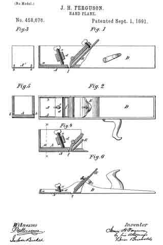
In the accompanying drawings, Figure 1 is a side elevation, partly in section, showing a plane embodying my improvement. Fig. 2 is a plan or top view of the same. Fig. 3 is an end view of the same. Fig. 4 is a sectional elevation illustrating a modification, certain of the parts being broken away to save space. Fig. 5 is a vertical section of the same, taken on the line x x, Fig. 4, certain of the parts shown in Fig. 4 being removed. Fig. 6 is a view in elevation, partly in section, illustrating how my improvement may be employed with another kind of plane.

Similar letters of reference designate corresponding parts in all the figures.

In the example of my improvement illustrated in Figs. 1, 2, and 3 the body of the plane is made in the form of a box and is formed of a single piece of metal — as, for instance, by casting. Near its forward end the face of the plane is provided with an elastic portion A, which normally occupies an elevated position, but which may be pressed downwardly at its inner end portion l, so as to regulate the depth of cut which will be made by the plane-iron E. In order to cause the requisite degree of elasticity, the portion A is separated throughout its length and upon its sides from the sides of the plane-body D by slits or slots b, which extend through the metal of the portion A and upwardly through the end A’ of the plane-body D. It will be seen that by pressing downwardly the inner end portion of the portion A its position may be deflected to any desired extent in order to increase the depth of cut which will be made by the plane-iron. In order to accomplish this deflecting of the portion A, I have shown a screw e, having bearings in a cross-piece d, secured in the sides of the plane-body. By manipulating this screw the deflecting or bending of the portion A may be regulated to any desired extent.

In the example of my improvement shown in Figs. 4 and 5 the operation is precisely like that just described; but there is some slight difference in the mode of constructing the slit or slot b. In this example the slot extends along the sides of the plane-body and downwardly at the inner end of the portion A. Of course the outer end of the portion A is not separate from the sides of the plane-body, except to the thickness of the sides of the body.

In Fig. 6 I have shown the application of the improvement to a so-called “jack-plane” having a body of cast metal. When used with the jack-plane, either one of the means for separating the portion A, so that it will be elastic, may be employed which I have described in the other examples of my improvement shown. I have, however, illustrated that as shown in Figs. 1, 2, and 3.

In all the examples of my improvement shown the portion A when occupying a normal position stands back slightly from the other part of the face of the plane, so that when in such a position the plane-iron will be capable of making its maximum cut.

It will be seen that by my improvement I provide a very inexpensive and ready means for varying the depth of cut which may be made by the plane-iron without going to the necessity of adjusting the plane-iron separately; or, in other words, the plane-iron once having been set it will not be necessary to alter it in order to obtain any desired adjustment for depth of cut.

What I claim as my invention, and desire to secure by Letters Patent, is —

The combination, with a plane-body made in one integral piece and having a portion of its face near one end elastic, but formed integral therewith, of an adjusting device operating upon said elastic portion to cause a deflection thereof, said elastic portion normally occupying a position whereby it is set in beyond the face, substantially as and for the purpose specified.

JAMES H. FERGUSON.

Witnesses:
FREDK. HAYNES,
JOHN BICKEL.

No. 336,222 – Edge-Guard For Planes (James H. Ferguson) (1886)

[paiddownloads id=”406″]336222


UNITED STATES PATENT OFFICE.

_________________

JAMES H. FERGUSON, OF BROOKLYN, ASSIGNOR TO
LOVEJOY, SON & Co., OF NEW YORK, N. Y.

EDGE-GUARD FOR PLANES.

_________________

SPECIFICATION forming part of Letters Patent No. 336,222, dated February 16, 1886.
Application filed October 3, 1885. Serial No. 178,870. (No model.)

_________________

To all whom it may concern:

Be it known that I, JAMES H. FERGUSON, of the city of Brooklyn, in the county of Kings and State of New York, have invented a new and Improved Edge-Guard for Planes, of which the following is a specification.

My invention is applicable both to planes in which the plane iron or knife is fixed in a stationary frame and performs its work when a piece of material is pushed over it, and to planes in which the iron or knife is fixed in a plane body or stock which is moved by hand over the work.

The object of my invention is to protect and shield or guard the knife so that it cannot receive injury by striking against any metal which would dull or chip its edge, and so that the hands of a workmen on a machine which comprises a plane iron or knife set in a stationary frame cannot be injured by coming in contact with the iron or knife.

To this end my invention consists in the combination, with the body and knife of a plane, of an edge-guard forming the edge of
the throat in front of the cutting-edge, and a spring for projecting the guard from the body so that it will shield the cutting-edge. This guard may be hinged at its side which is most distant from the cutting-edge of the plane-iron, and this arrangement therefore also forms a part of my invention.

In the accompanying drawings, Figure 1 is a sectional view of a portion of a stationary frame in which a plane-iron is fixed and an edge-guard, embodying my invention; and Fig. 2 is a sectional view of a hand-plane, also embodying my invention.

Similar letters of reference designate corresponding parts in both figures.

Referring first to Fig. 1, which represents my invention as employed in connection with a plane iron or knife fixed in a stationary frame, a designates the iron or knife, which is presented upward through the throat b. In order to shield and protect the cutting-edge of the plane-iron a and prevent injury to it by reason of striking any hard-metal articles against it, and also to prevent the hands of the workmen from being injured by contact therewith, I employ an edge-guard, E, which is here represented as hinged at e at the side most distant from the cutting-edge of the iron a in the frame of the machine. This guard is projected upward by means of the spring c, so that its forward edge will be presented as far above the frame of the plane as the cutting-edge of the iron a, and the free edge of the guard E forms the front wall of the throat through which the plane-iron a is projected. The spring c, although sufficiently strong to hold the guard E in its upward position and prevent accidental contact with the edge of the plane-iron a, is, however, weak enough to yield when an article or piece of material is pressed down on the bed or frame and moved across the plane-iron a. My invention. as illustrated in Fig. 1, may be employed for planing wood or soft metal — such, for example, as beveling off the edges of stereotype and electrotype plates. In Fig. 2 I have represented an ordinary hand-plane, of which F designates the body, and a the plane-iron, the edge of which is presented at the under side of the body through a throat, b. This plane-body has secured in it at the under side a guard, E, which is hinged at e at the side most distant from the cutting edge of the iron a, and which is projected downward by a spring, c, so that its forward edge, which forms the front of the throat b, will protrude from the under side of the body to as great or greater extent as the cutting-edge of the iron a. The spring c should be of such strength that when the plane is at rest upon a bench or other support the projection of the guard will be such as to hold the cutting-edge out of contact with the support and to prevent its contact with different articles which would impair or dull the cutting-edge. The strength of the spring must, however, be such that when pressure is applied to the body of the plane when in use the guard E will yield to such pressure and will enable the cutting-edge of the iron a to perform its work.

I am aware that it is not new to provide the body of a carpenter’s plane with yielding disks or plates upon the under side which are pressed outward by springs, so that when the plane is at rest upon a bench or other support they will project sufficiently far upon the under side of the body to hold the cutting-edge of the iron out of contact with the support. These yielding disks or plates are, however, remote from the throat of the plane, and do not perform the function of my edge-guard E in protecting the edge of the cutting iron or knife, as they do not form the edge of the throat in front of the cutting-edge.

What I claim as my invention, and desire to secure by Letters Patent, is —

1. The combination, with the body and knife of a plane, of an edge-guard forming the edge of the throat of the cutting-edge, and a spring for projecting the guard from the body so that it will shield the cutting-edge, substantially as herein described.

2. The combination, with the body and knife of a plane, of an edge-guard forming the edge of the throat in front of the cutting-edge and hinged at its side which is most distant from the cutting-edge, and a spring for projecting the guard from the body so that it will shield the cutting-edge, substantially as herein described.

JAMES H. FERGUSON.

Witnesses:
FREDK. HAYNES,
HENRY McBRIDE.

Correction in Letters Patent No. 336,222.

It is hereby certified that in Letters Patent No. 336,222, granted February 16, 1886, upon the application of James H. Ferguson, of Brooklyn, N. Y., for an improvement in “Edge-Guards for Planes,” certain words were erroneously omitted in printing the specification, which should be supplied, to wit: In line 11, page 2, after the word “throat” the words in front should be inserted; and the Letters Patent should be read with this correction therein to conform to the record of the case in the Patent Office.

Signed, countersigned, and sealed this 23d day of February, A. D. 1886.

[SEAL.]

H. L. MULDROW,
Acting Secretory of the Interior.

Countersigned:
M. V. MONTGOMERY,
Commissioner’ of Patents.