
No. 778,849 – Wood-Scraper (James R. Ellis) (1905)

UNITED STATES PATENT OFFICE.
_________________
JAMES R. ELLIS, OF CLEVELAND, OHIO.
WOOD-SCRAPER.
_________________
SPECIFICATION forming part of Letters Patent No. 778,849, dated January 3, 1905.
Application filed July 27, 1904. Serial No. 218,415.
_________________
To all whom it may concern:
Be it known that I, JAMES R. ELLIS, a citizen of the United States, residing at Cleveland, in the county of Cuyahoga and State of Ohio, have invented new and useful Improvements in Wood-Scrapers, of which the following is a specification.
This invention is an improved wood-scraper for the use of carpenters and cabinet-makers, and is characterized particularly by improvement with respect to the manner in which and the means by which the scraping-blade is held in the stock and also by other improved details of construction, as will be more fully apparent from the following description.
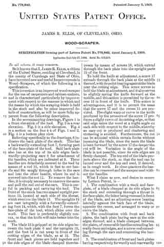
In the accompanying drawings, Figure 1 is a front elevation of the tool. Fig. 2 is a rear elevation. Fig. 3 is a side elevation. Fig. 4 is a section on the line 4 4 of Figs. 1 and 2. Fig. 5 is a bottom plan view.
Referring specifically to the drawings, 6 indicates the back plate of the stock. This has a backwardly-extending foot 7, forming part of the face-plate of the tool. Said back plate also has at the top of its side edges backwardly-projecting ears 8 for attachment of the handles, which are indicated at 9. These handles are detachably secured to the tool by means of a rod 10, which is fast to one handle and fits snugly through holes in the ears and into the other handle, where its end is screwed into the nut 11. To remove the handles, it is simply necessary to unscrew the same and pull the rod out of the ears. This is useful in packing and carrying the tool. The front of the stock has two spaced upright portions 12, located at each side of the throat, which receives the blade 13. The uprights 12 are cast integrally with a forwardly-extending foot 14, which, with the foot 7, forms the face-plate of the tool, which slides over the work. This face is preferably slightly convex, so that the knife will take better into the work.
The blade 13 is gripped at its side edges between the back plate 6 and the uprights 12, and the foot 14 is cut away in front of the cutting edges of the blade, as at 15. The front and back pieces are held together and the side edges of the blade clamped therebetween by means of screws 16, which extend through the back plate into the upright parts 12 of the front.
To hold the knife at adjustment, a screw 17 extends through the back plate at the middle thereof, with its point bearing against the blade near the cutting edge. This screw serves to hold the blade at adjustment, and it also serves to slightly spring the knife forward at the middle, and this action is permitted by the recess 15 in front of the knife. This action is advantageous, and it is to permit the same that the screw 17 and the recess 15 are provided. The slight warp or curve in the knife produced by the pressure of the screw 17 produces a slight curve of its cutting edge, so that said edge takes the wood at a slight angle on each side with respect to the middle, whereby an easy cut is produced and chattering and stuttering is avoided. Furthermore, the cut can be adjusted within certain limits without loosening the blade, since the more the blade is bent forward by the screw 17 the deeper the cut will be. Variation in the angle of the blade is not possible, since its side edges are firmly clamped. The top end of the blade projects above the stock, so that the tool can be turned over and the top end used, if desired, as in rough work. In close quarters the handles can be removed and the scraper used without the handles.
What I claim as new, and desire to secure by Letters Patent, is —
1. The combination with a stock and face-plate, of a blade clamped at its side edges in the stock and extending through a throat in the face-plate, the latter being recessed in front of the blade, and an adjusting-screw bearing laterally against the back face of the blade, opposite the recess, and arranged to warp or curve the blade.
2. The combination with front and back plates, the back plate having ears at the side edges thereof, and a blade clamped between the plates, of removable handles extending laterally from said edges, and a screw-rod extending through the ears and connecting the handles.
3. The combination of front and back plates having respectively forwardly and rearwardly extending feet forming a face-plate, a blade clamped at its side edges, only, between the plates, the front plate being recessed in front of the blade, and an adjusting-screw extending through the back plate and bearing against the blade, and arranged to warp or curve the blade.
In testimony whereof I have signed my name to this specification in the presence of two subscribing witnesses.
JAMES R. ELLIS.
Witnesses:
SHIRLEY BOMMHARDT,
JOHN A. BOMMHARDT.